|
|
|
I know nothing about this additional prototype:
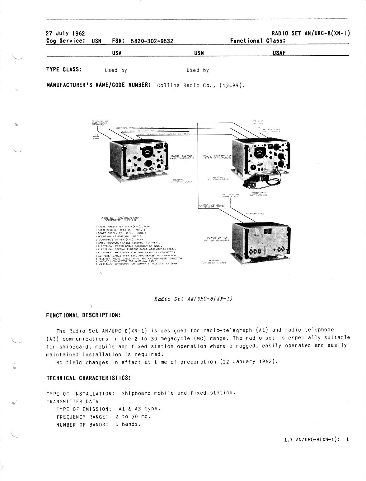
AN/URC-8 (XN-2) Trans-Receiver Radio Set.
CBS LABS NEW YORK
NAVSHIPS 92927
Info from John K4OZY:
First, a thousand thanks to Ken Bodensteiner @ Rockwell/Collins who came up with
some advertising brochures for the URC-8.
Turns out it was intended as a
replacement for the TCS! You can view the brochures by clicking here: URC8
Brochure [PDF File]
URC-8 consists of
| Mil Name | Collins Part # | Description |
|---|---|---|
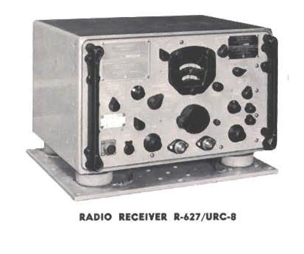
| R-627 | 522-9273-004 | Receiver, 2-30 Mc, 4 bands, AM/CW only, 2 mech filters, 107 lbs PTO or xtal control internal p/s - 115/230 v ac input 50-60 or 400 cps |
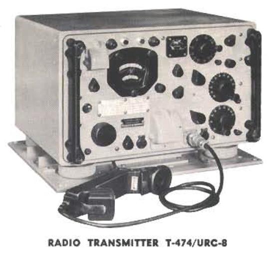
| T-474 | 522-0583-006 | Transmitter, 2-30 Mc, AM/CW, 102 lbs PTO or xtal control 42w output to 15-35' whip antenna |
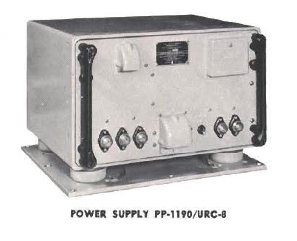
| PP-1190 | 522-0584-006 | Power supply for transmitter, 137 lbs 115/230 v ac input 50-60 or 400 cps |
| Optional Motor-Generators | ||
| PU-340(XN-1)/U | -- | 12 v dc input |
| PU-340(XN-1)/U | -- | 28 v dc input |
| PU-340(XN-1)/U | -- | 115/230 v dc input |
Thanks to Jim Jones (W0NKN) @ Rockwell/Collins for the Collins P/N's! URC-8
is listed on various military equipment lists, which generally say that the
receiver requires PP-1190.
This is clearly not the case, as the receiver has an
internal power supply (see pix below).
The PP-1190 must, therefore, power the
T-474. There's also an auxiliary DC Converter (187 lbs) that allowed running the
set off a variety of DC and AC supply voltages.
The manuals are NAVSHIPS 92831 and 92927 (1957). Robert Downs (THANKS!) supplied the following additional info:
| Old Number | New Number | Description |
|---|---|---|
| NS 92831 | -- ? | RADIO SET AN/URC-8(XN-1), IB 26 JUL 1956 |
| NS 92927 | 0280-LP-417-2000 | RADIO SET AN/URC-8(XN-2), IB JAN 1957 |
If you have ANY information about this receiver or the URC-8 equipment group, please send me mail
T-474(XN-1)/URC-8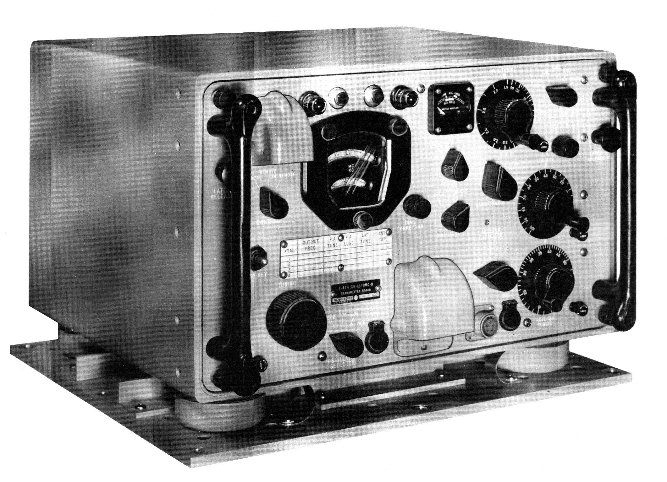 |
T-474(XN-1)/URC-8 |
T-474(XN-1)/URC-8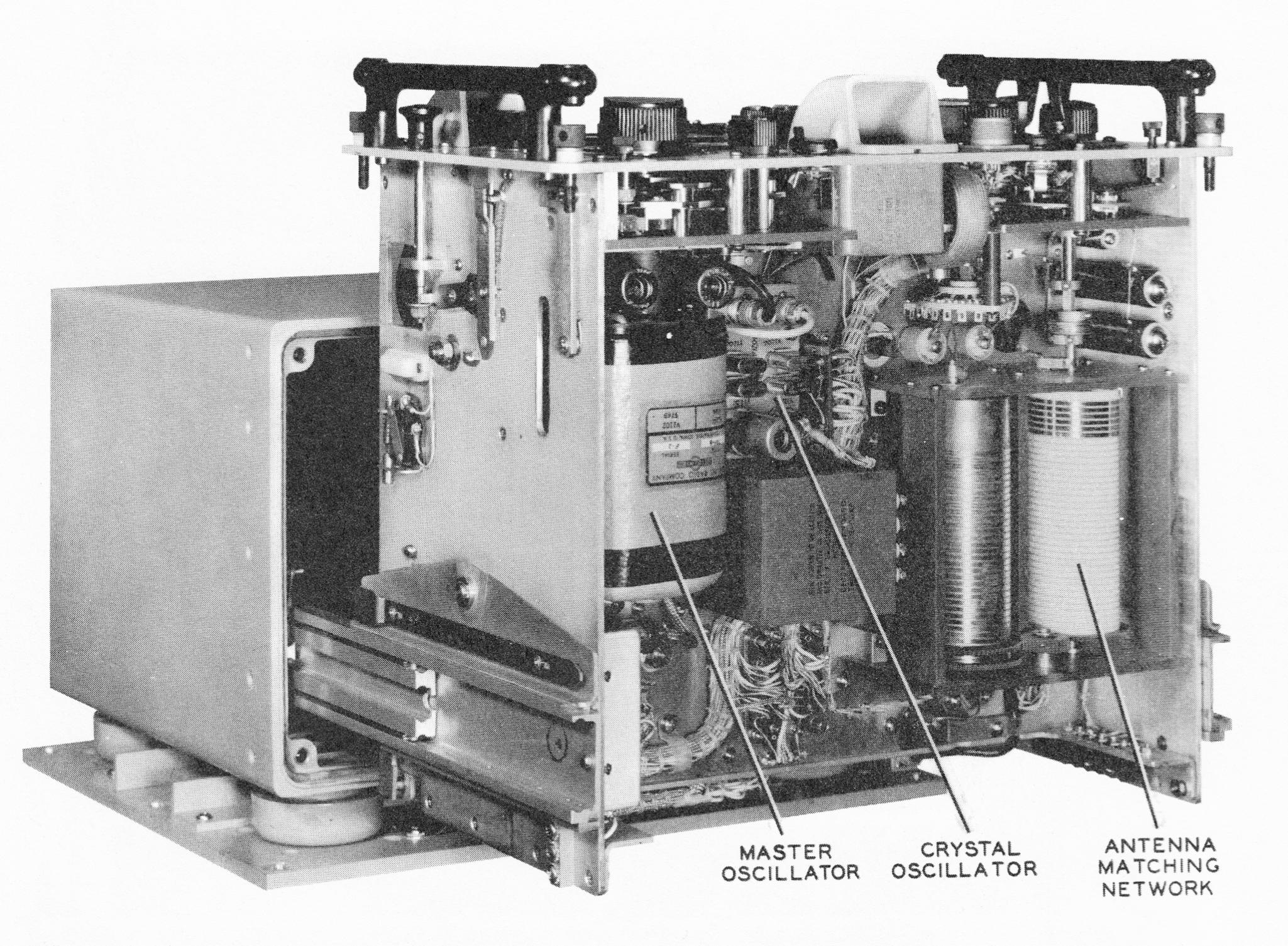 |
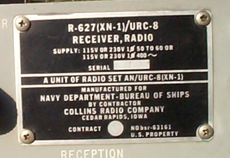
R-627(XN-1)/URC-8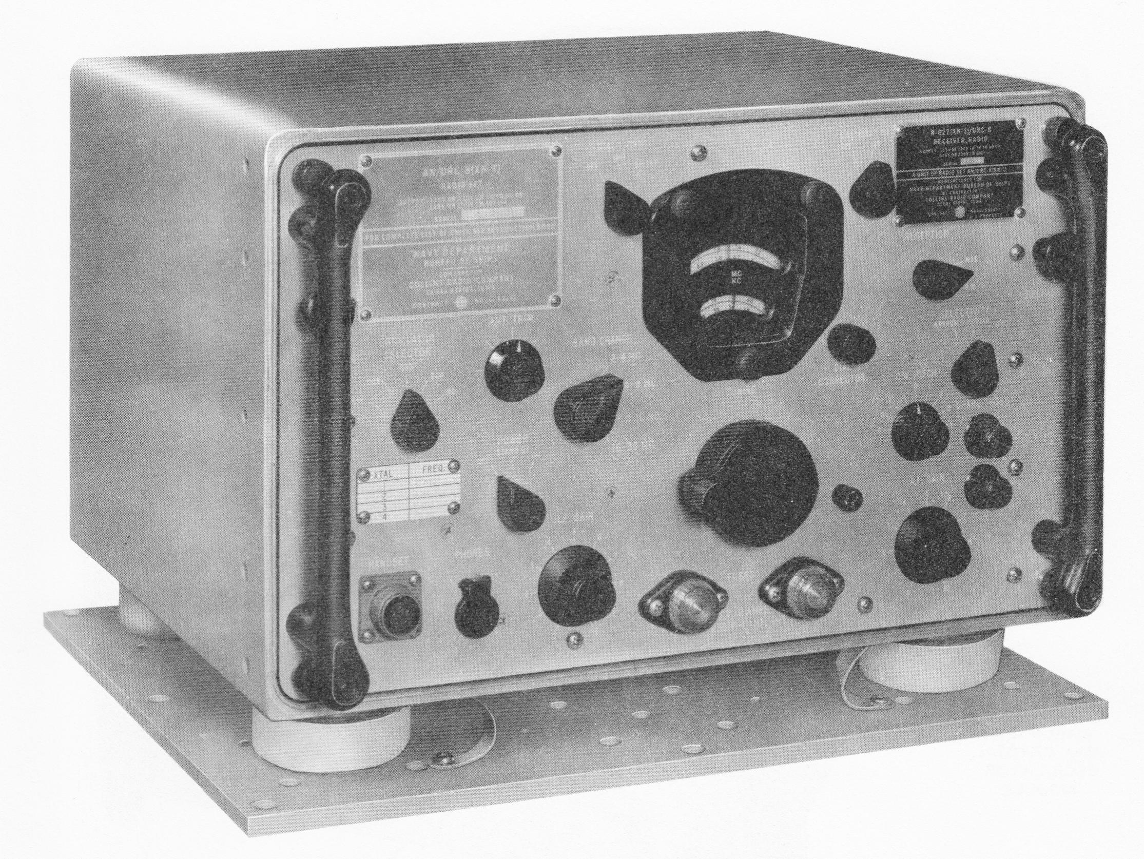 |
R-627(XN-1)/URC-8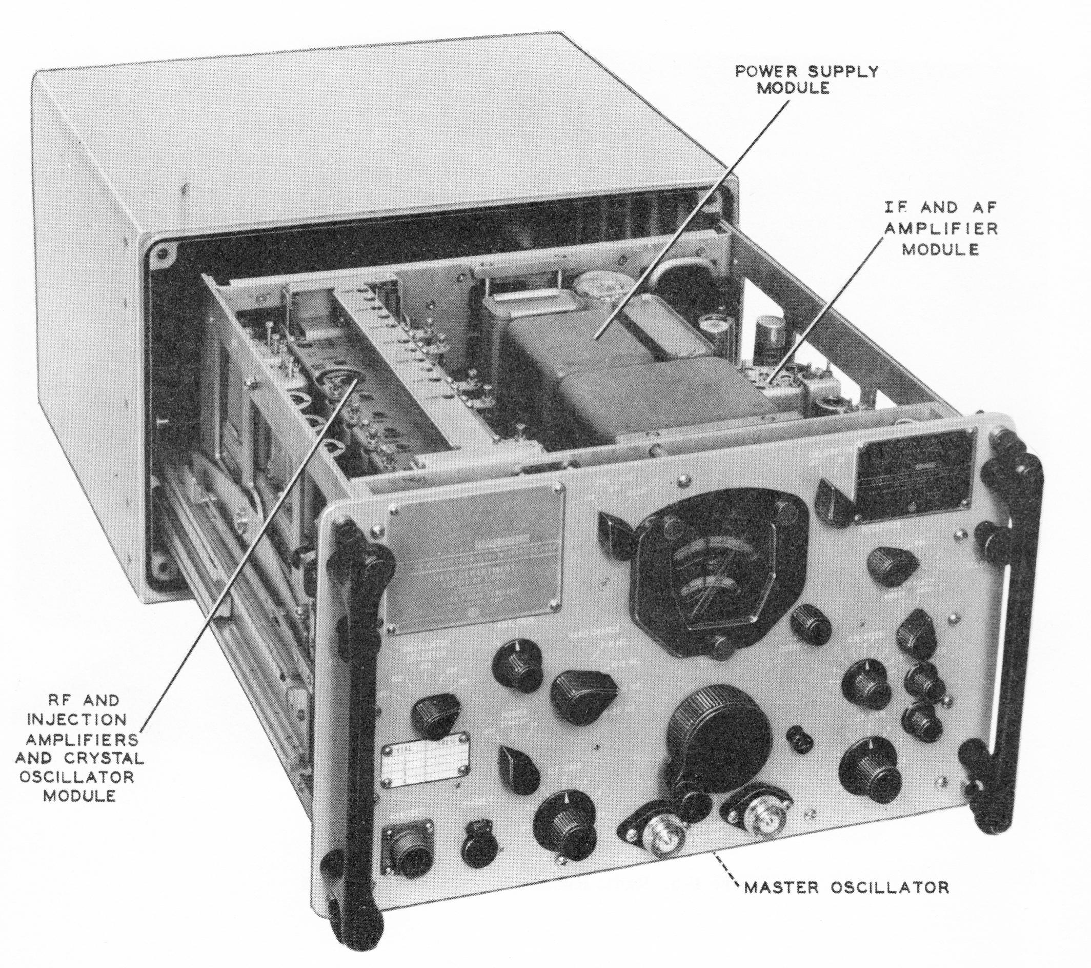 |
PP-1190(XN-1)/URC-8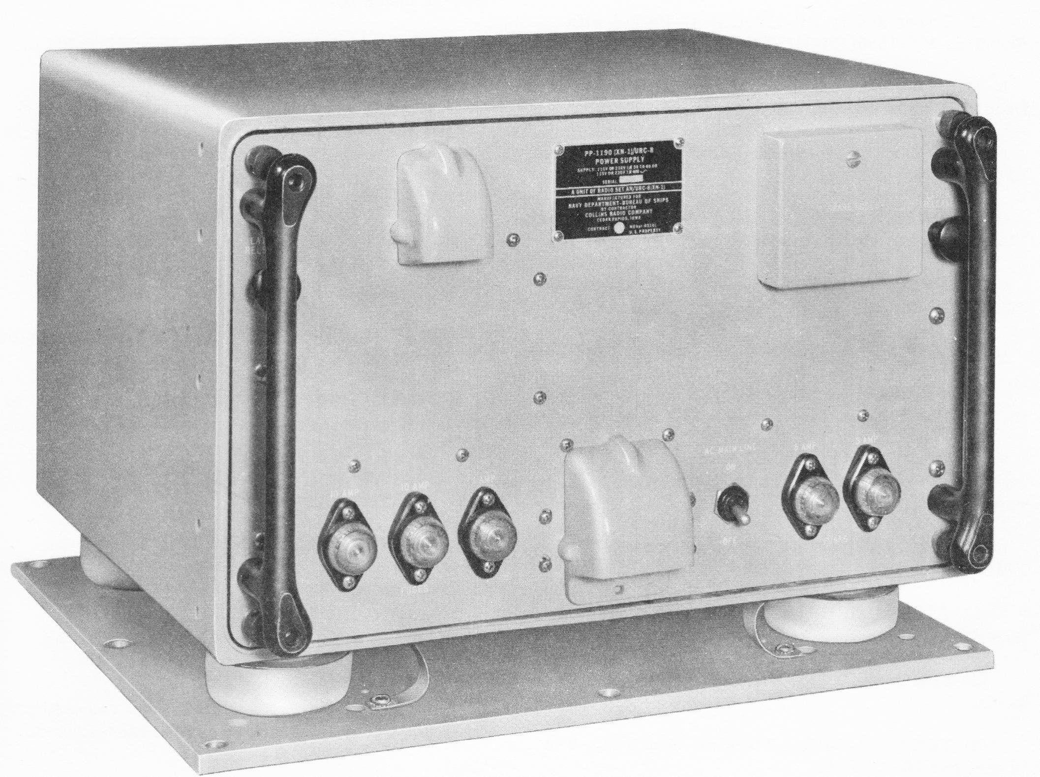 |
| R-627/URC-8 HF Radio Receiver The complete radio with separate boxes for transmitter, receiver and power supply was intended as a successor to the WW2 TCS. It was general purpose HF radio covering 2-30 MHz in four bands of one octave. Like all Collins radios, the frequency setting was an order of magnitude better than all other contemporary radios. The project was acquired from the U.S. Navy by the Collins at Cedar Rapids, however the receiver design was delegated to the Western Division. Mel Doelz handed me the specifications, and he gave me his opinion on how the conversion scheme should work. Unless some weakness was found, this was the order on how to do it. A little later, Dick Bridges was chosen for the project head. The description of this radio may be found on the internet from official sources, and from some hobby-radio sources. This radio had an unusual conversion scheme. If I recall correctly, local oscillator was on the same frequency as an intermediate frequency amplifier making careful shielding and decoupling imperative. The arrangement made the coverage in four bands each an octave wide: 2-4, 4-8, 8-16, and 16-30 MHz. The big challenge was the design of the signal frequency tuned-circuits. It started with the design of the dial mechanism with fixed calibration. The frequency had to be a straight line function in kHz. The front end tuned-circuits were adjusted by the 1" travel of cylindrical ferrite cores moving up/down in the center of the inductor. To achieve this linear relationship between position and resonant frequency require variable pitch winding. I had a hand in building the machine to do the winding with arbitrary pitch patterns. Eventually the magic proportions were found for the four bands. The Collins permeability-tuned local oscillator was very artful so that the screw thread which advance the core into the inductor was inherently linear with a variable pitch winding with an added second order correction. This was a component to our design group. The design of the dial mechanism, was the work of a real mechanical engineer, not a converted electrical engineer. All of the parts relating to frequency tuning were keyed back to a hard definition of the ratio's between local oscillator, dial and slug travel in the front end tuned circuits. As far as I know, there were only four of these radio built and delivered to the Navy. Probably it was too late for a non-SSB radio to be needed. Also smaller, lighter radios were becoming possible. |
Specification Sheets |
|||
 |
|
|
|
|
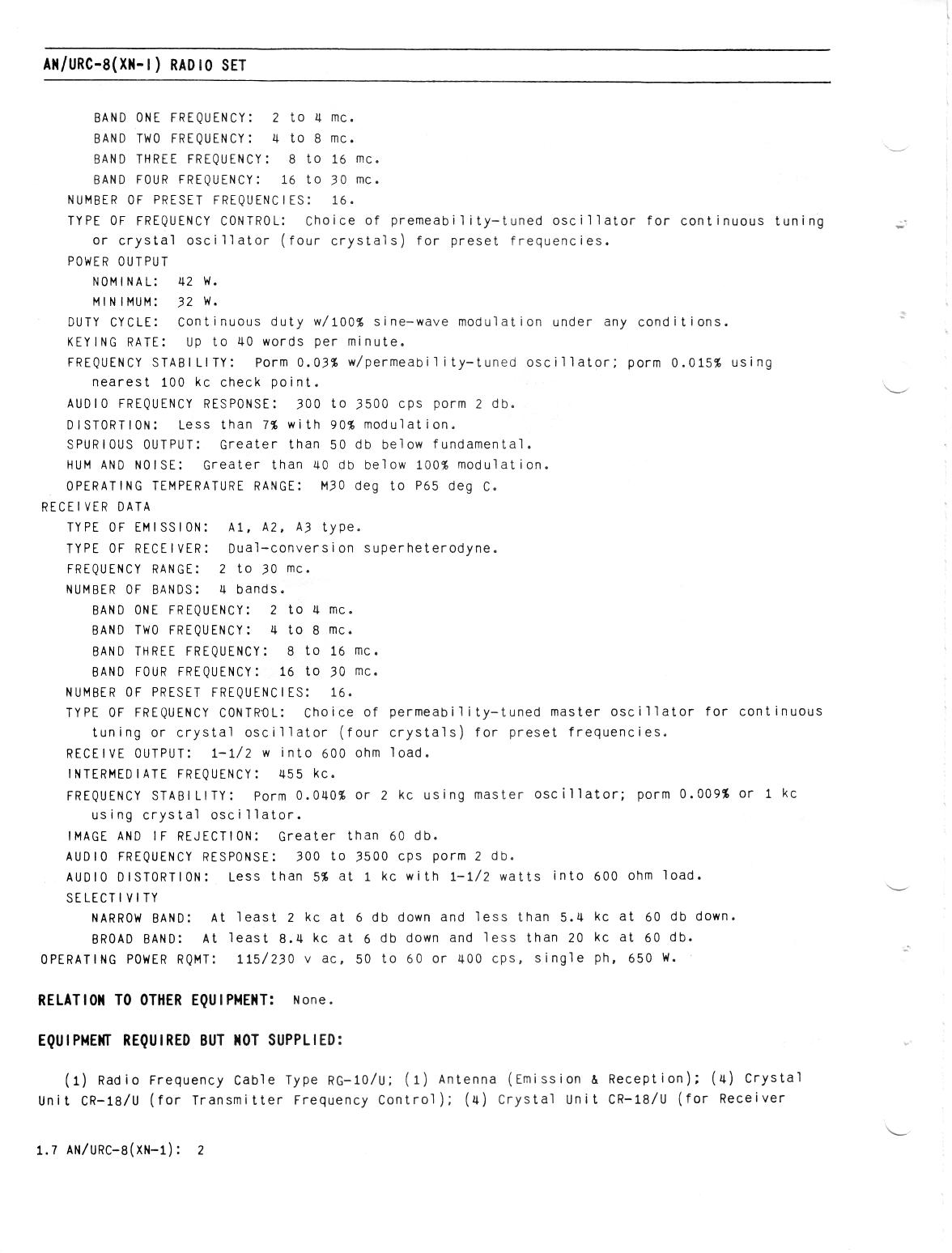
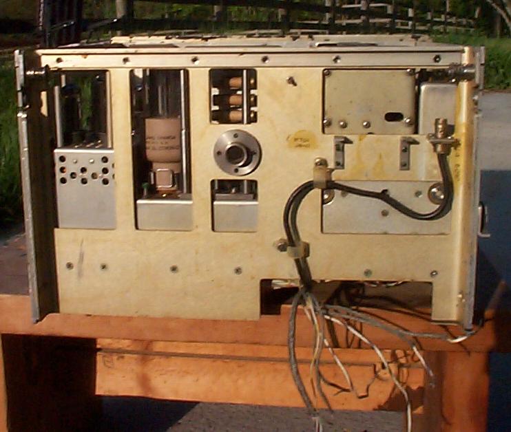
R-627/URC-8 Front view
|
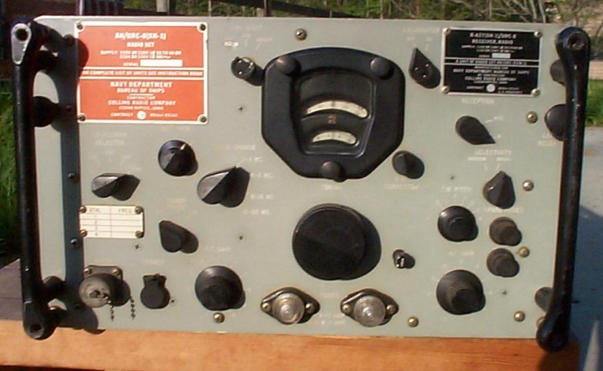
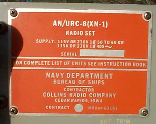
Serial number 4
|
Serial number 4
|
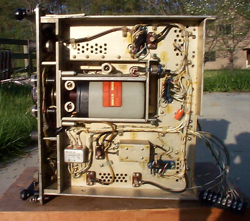
Rear view
|
| The receiver uses modular construction somewhat like that employed in the R-390A. There's an RF, IF/AF, and power supply module, secured into the mainframe with the famous green screws. | |||
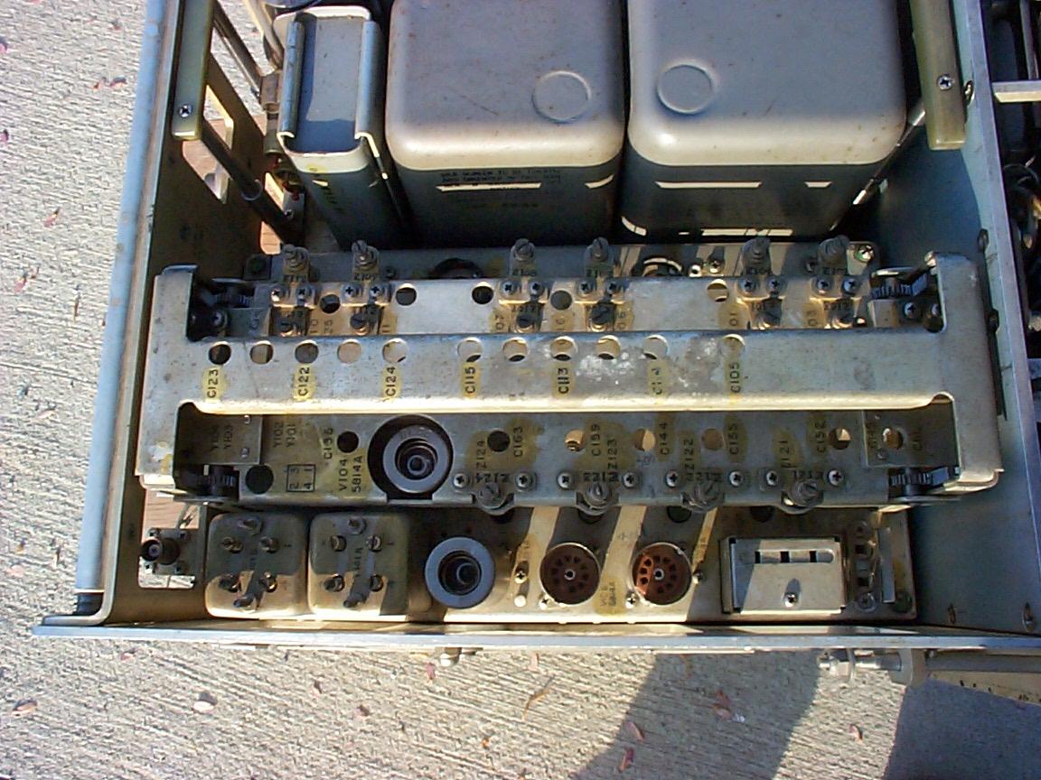
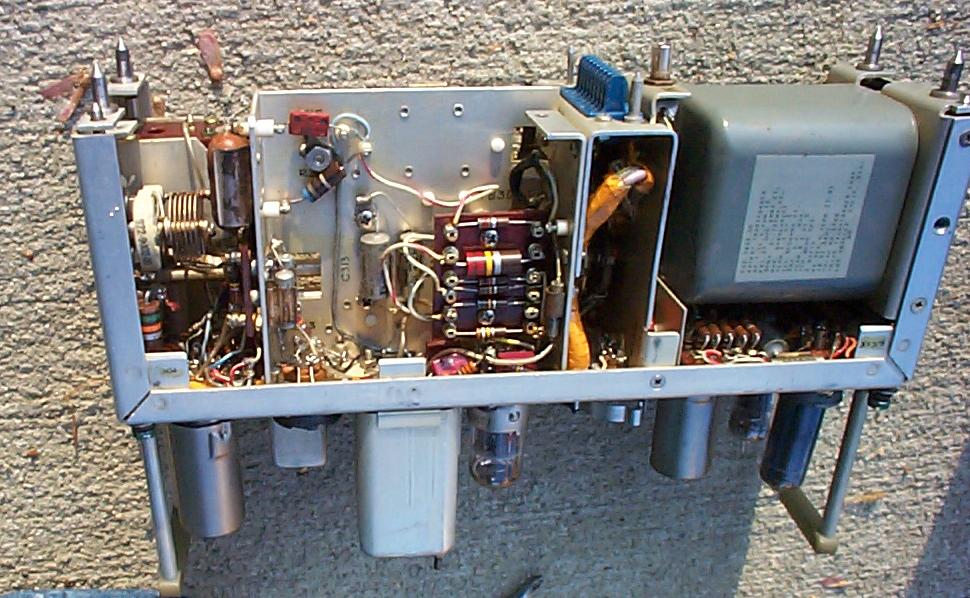
| Top left view, showing RF module at bottom of photo:
|
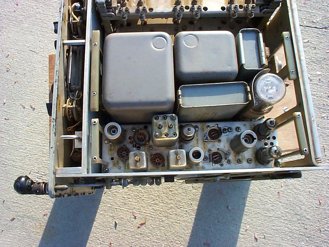
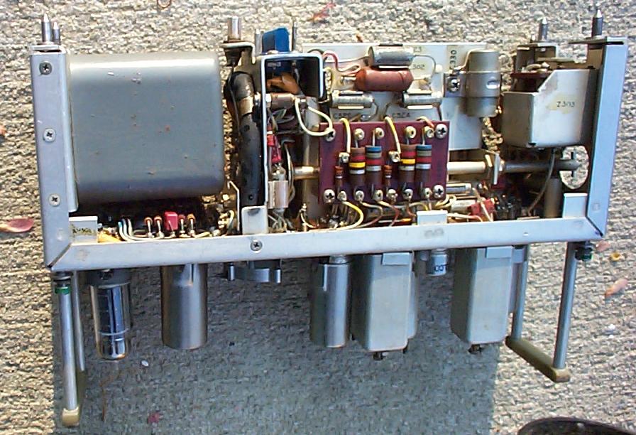
Top right view, showing IF/AF module at bottom of photo:
|
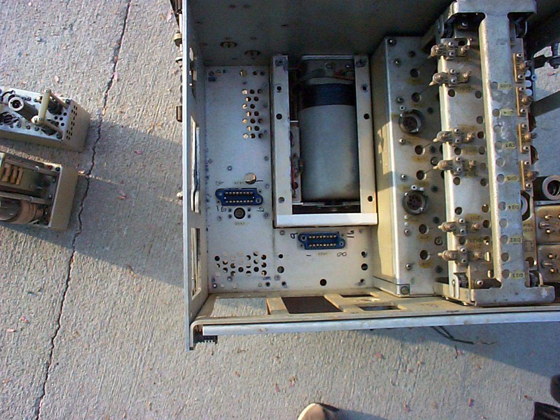
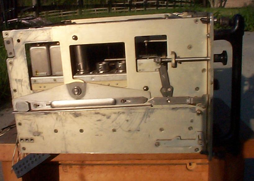
IF/AF and Power supply modules remove quite easily. Below are images of
the partially emptied mainframe, with the PTO showing below the power
supply module location. Also shown are the modules removed.
|
Bottom view
|
|
Left side
|
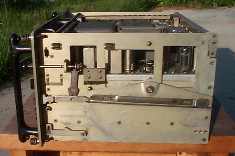
Right side
|
The PTO is a Collins 70H-10, which tunes from 2.58 - 4.58 Mc. The front panel contains a switch to select the PTO ("MO"), or one of four internal crystals, which in this receiver are at 2.58, 3.58, 4.33, 4.58 Mc. PTO tubes are a pair of 5749's. To the right is a close-up of the PTO nestled in the bottom of the rx. | 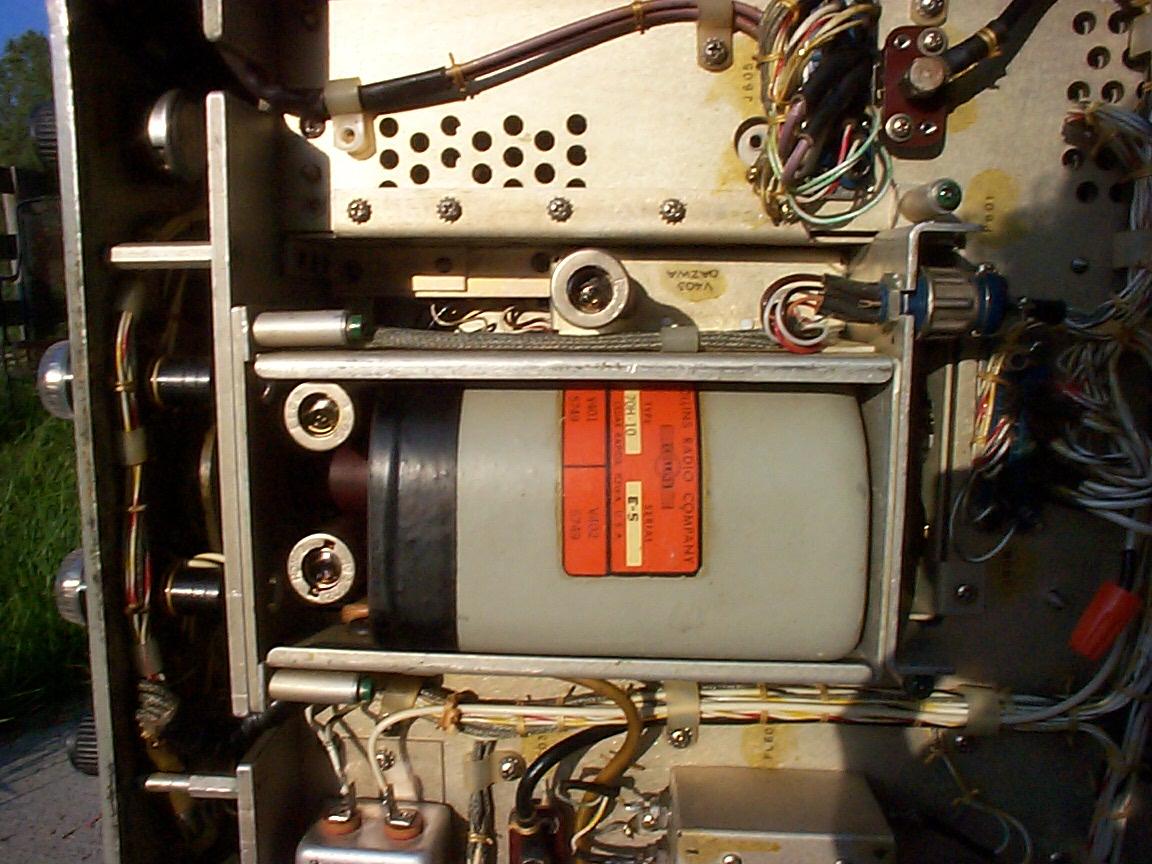
|
| Inside of the IF/AF module. AF uses a pair of 6005's (6AQ5's) in P/P with 600-ohm output. | |||
 |
|
- | - |
Nick's June 2011 notes on R-627/URC-8 s/n 4 - with no manual or other info
- Dual conversion, general coverage 2-30 mc in 4 bands.
One piece of info says 455kc 2nd IF and there are two empty mechanical filter
sockets in the IF/BFO/AF module
There is a 70H-10 PTO (2.58-4.58 mc) as the HF oscillator.
I had been trying to figure out the conversion scheme and beyond figuring the
PTO was multiplied as follows,
had been scratching my head as I saw only one crystal socket that could act as
the fixed LO for the 2nd converter.
Band (mc) multiplier
PTO x multiplier (mc)
2-4
x1
2.58-4.58
4-8
x2
5.16-9.16
8-16
x4
10.32-18.32
16-32
x8
20.64-36.64
Then eureka, I finally found 4 xtals buried deep within the RF deck - this is a
really compact bugger, but with flashlight and magnifier
I managed to read the freqs. Here is my guess at the conversion scheme - using
mid-band for illustrative purposes.
(freq in kc)
RF input PTO x mult
1st-IF XTAL
2nd-IF
3000
3580
580
1035 455
6000
7160
1160
1615 455
12000
14320
2320
2775 455
24000
28640
4640
5095 455
Yep, I found a couple of IF transformers with 4 coils/housing so it probably
really does have a different 1st IF for each band.
And the extra xtal socket I had identified earlier is for the 100kc calibrator
xtal.