RECEIVING RF SIGNAL DISTRIBUTION - (reference NAVSHIPS 91047 and NAVSHIPS 900,121) |
||||
SDU |
RF and AF Signal Distribution Unit Type A,
B, C 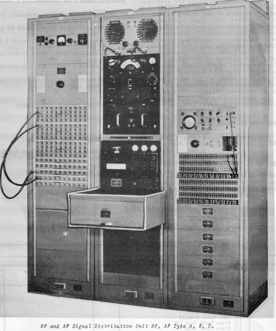 |
for communication station receiving sites
Please send e-mail if you have any parts of an SDU |
manual is NAVSHIPS 91047 | - |
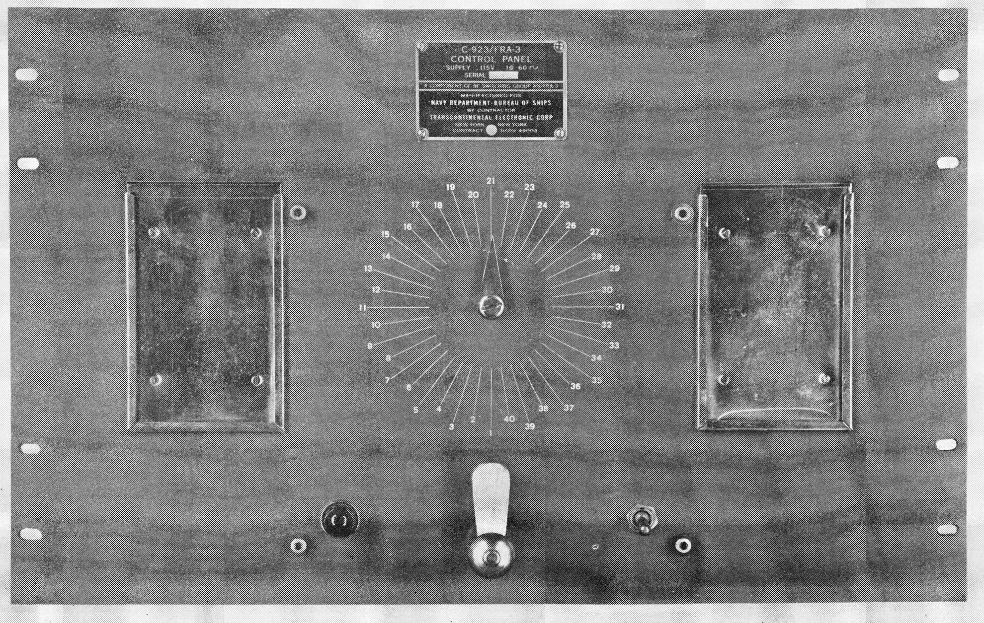
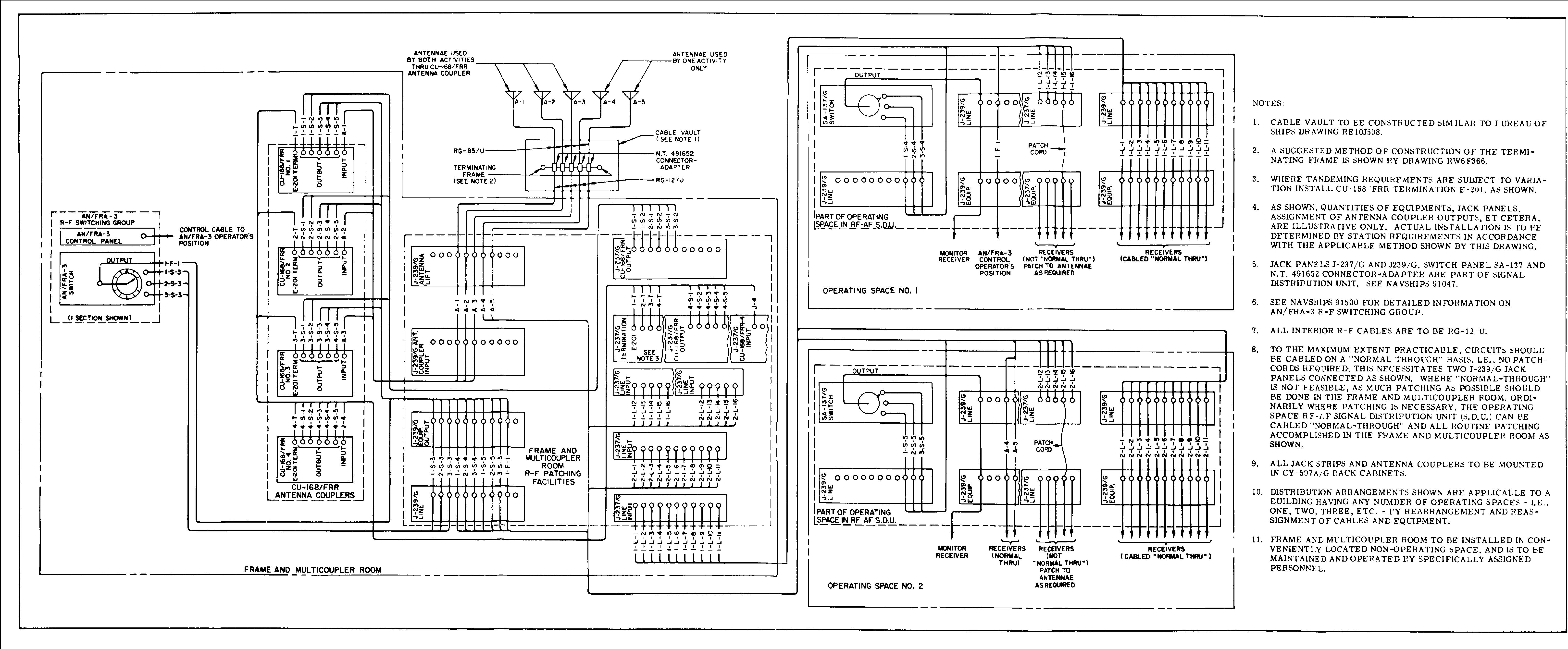
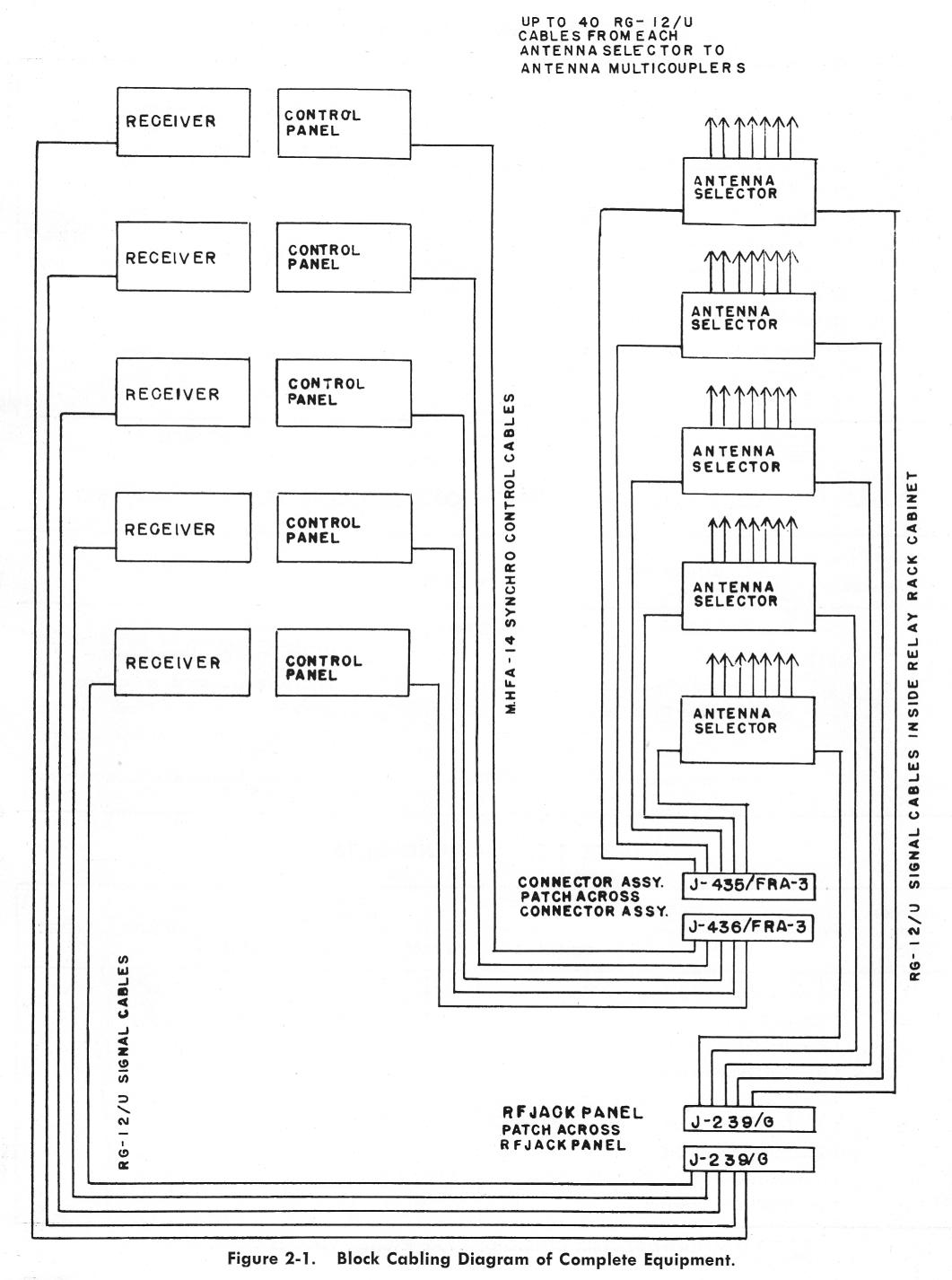
AN/FRA-3 |
RF switching group for shore station receiver installations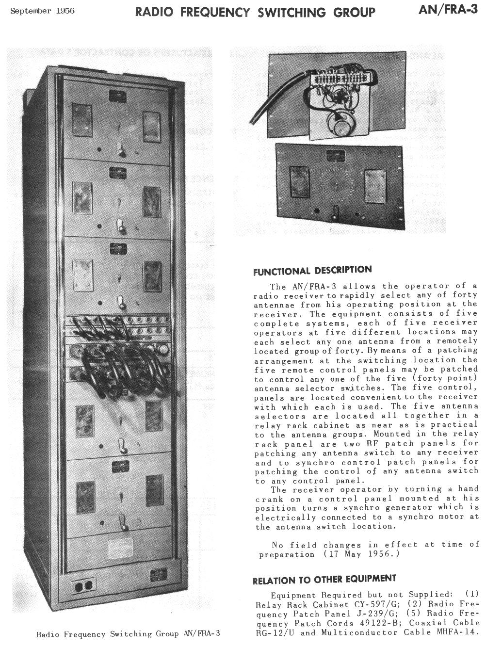 |
Allows 5 operators to remotely select one of 40 antennas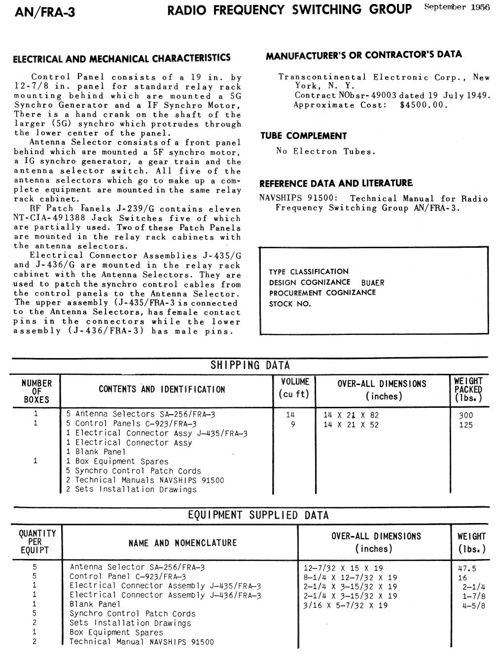 |
RF distribution diagram
NAVSHIPS 91500 - Please send e-mail if you have any parts of AN/FRA-3 Remote Control Panel C-923/FRA-3
|
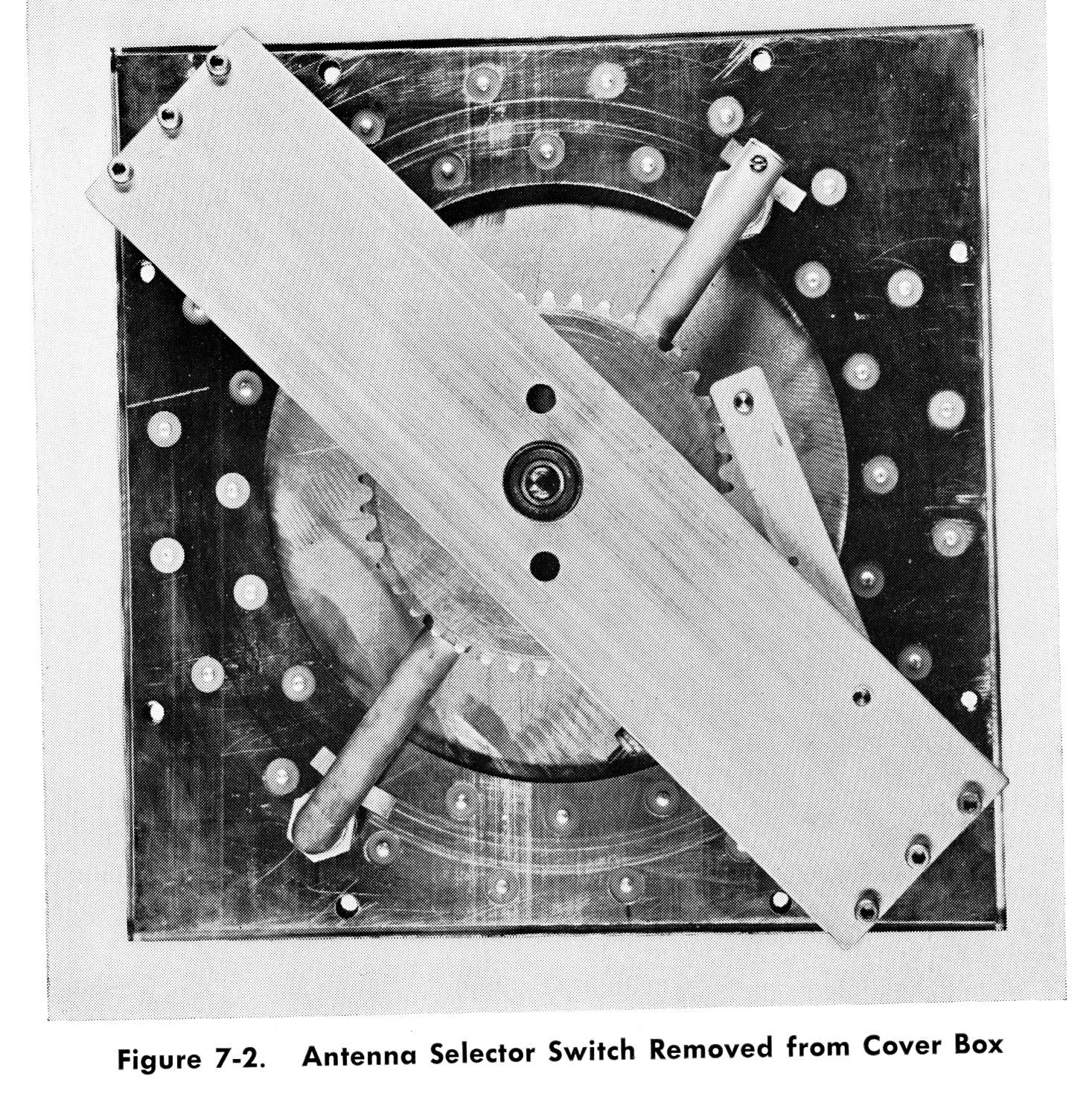
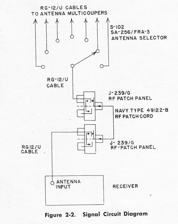
Antenna Selector SA-256/FRA-3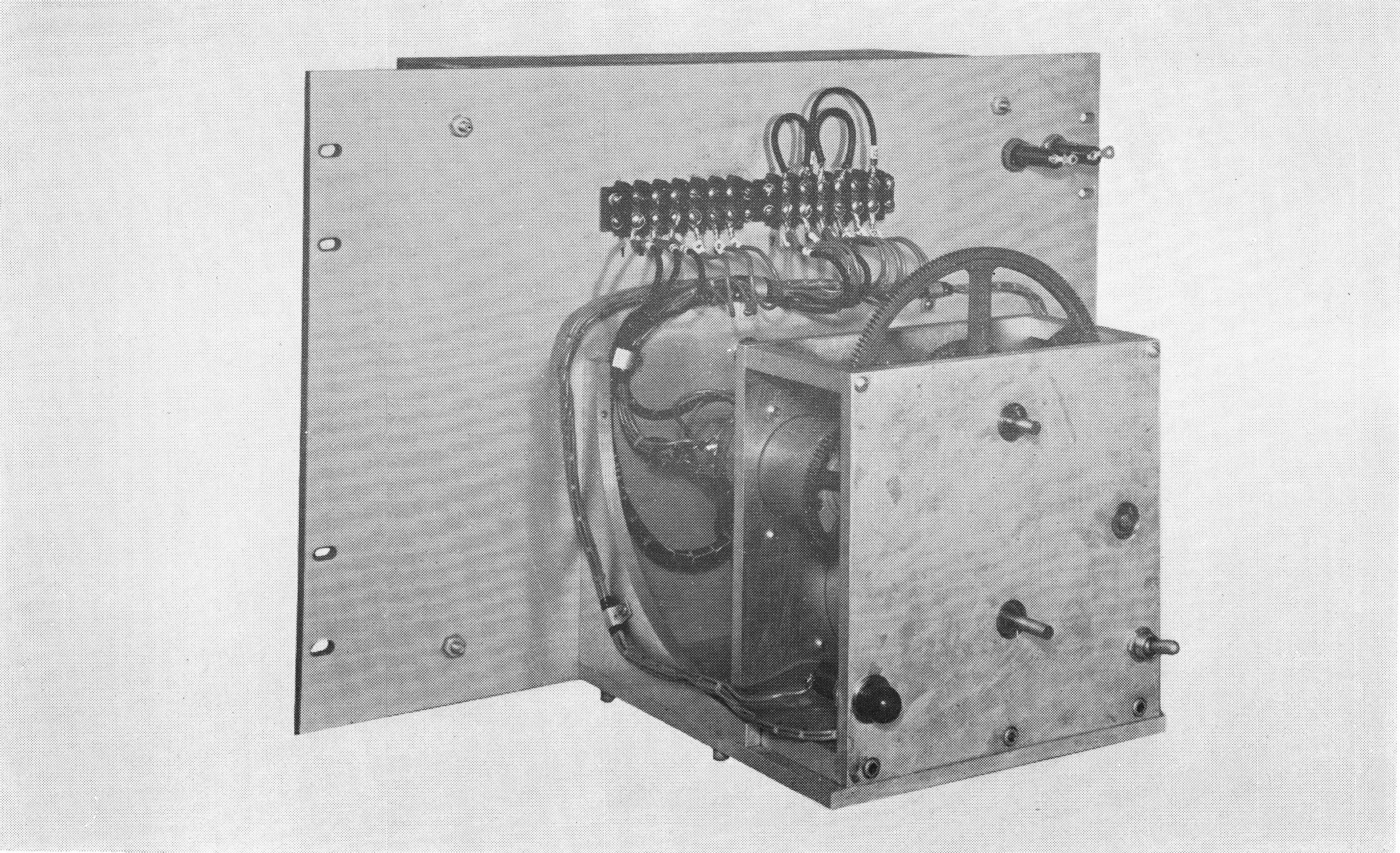
|
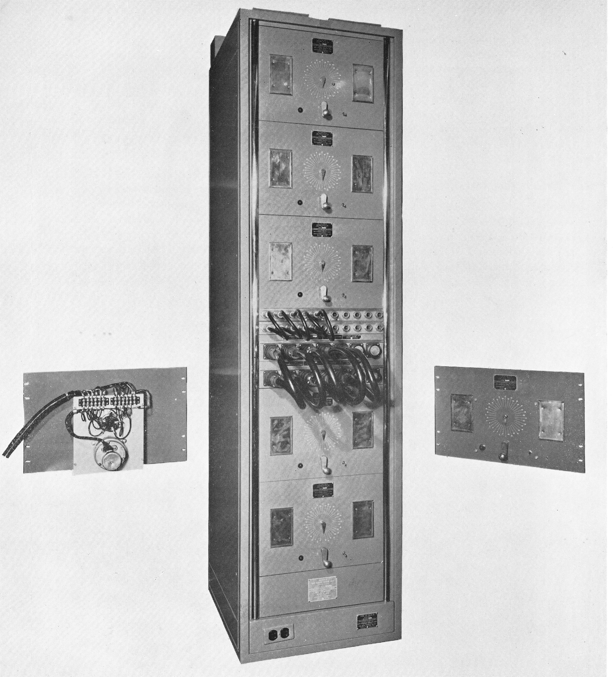
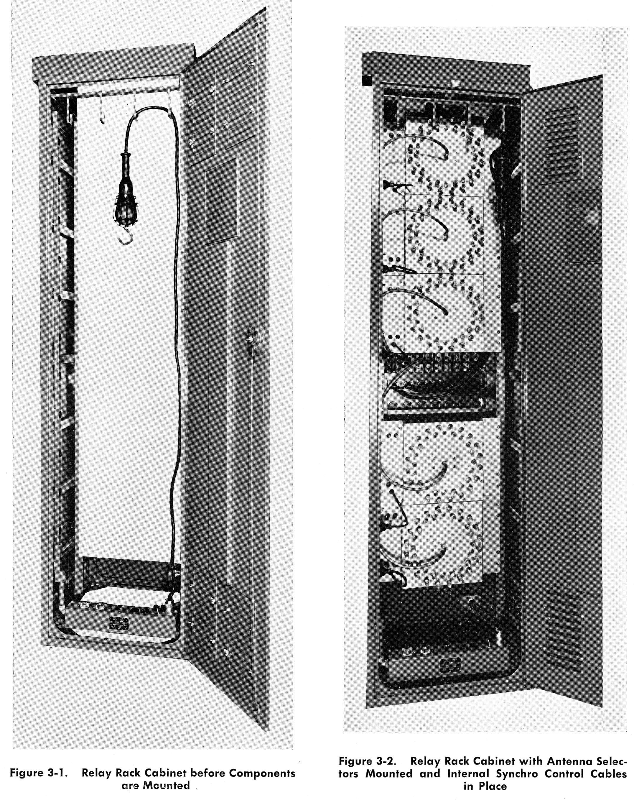
AN/FRA-3 |
|
|
|
|
NT-23404
|

|
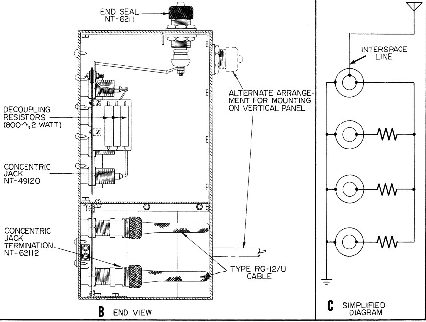
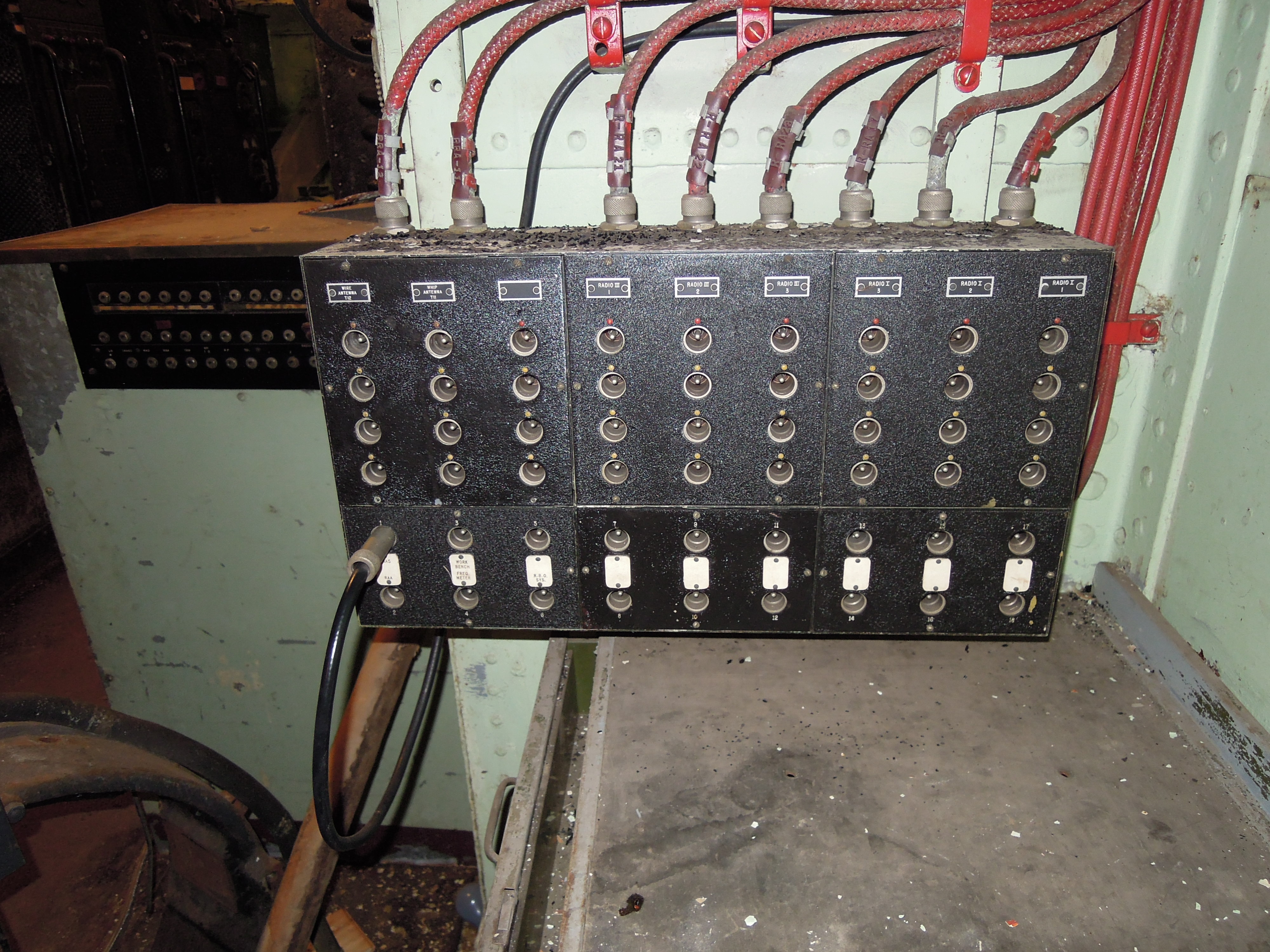
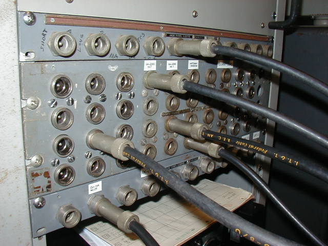
Antenna and Interspace RF patch panels
|
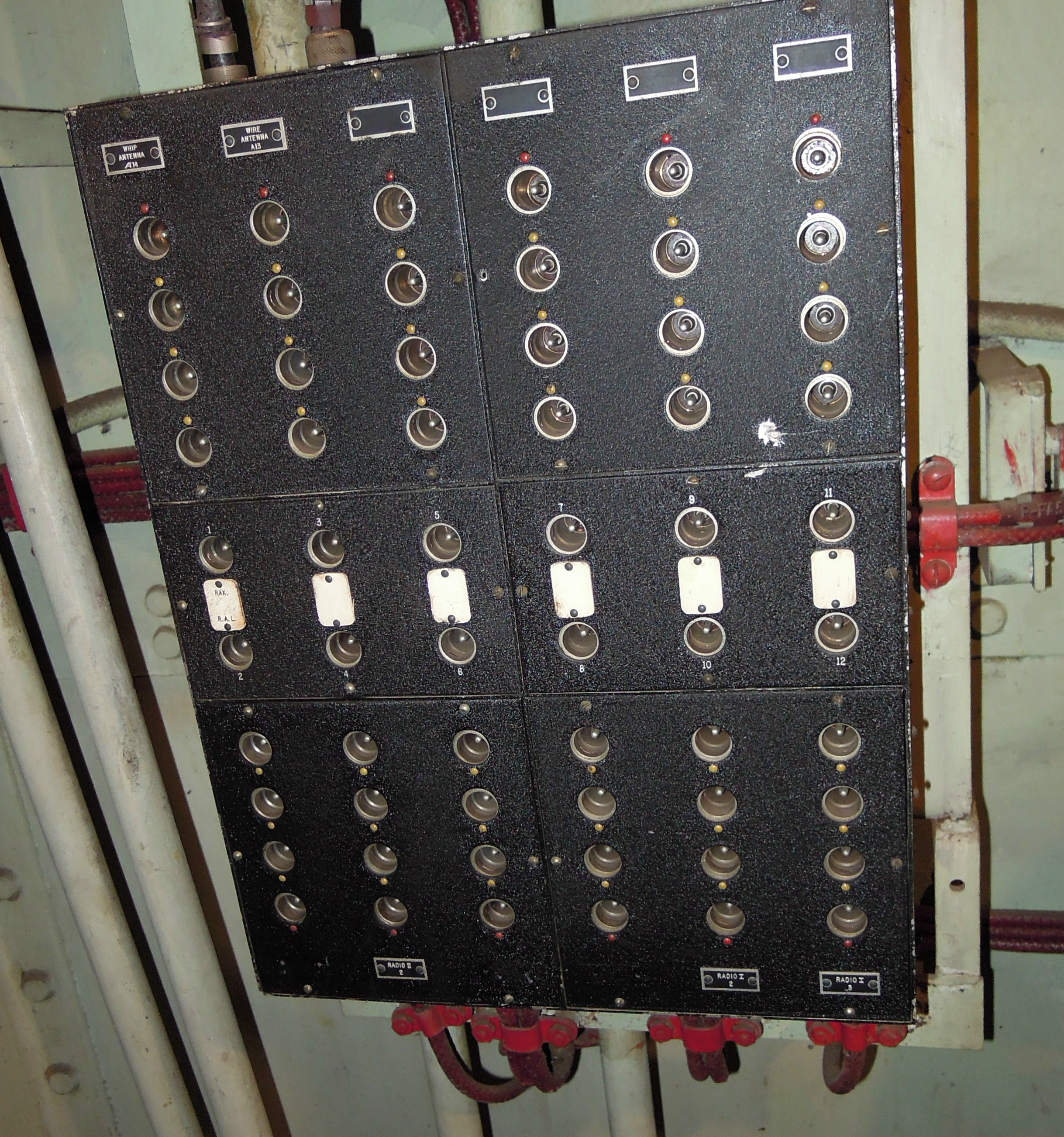 NT-23407 in Radio III aboard BB-35 (12 in, 12 out) |
 NT-23404 in Radio I aboard BB-55 (30 in, 30 out) |
|
23404 -
30 antennas, 30 receivers 23405 - 18 antennas, 18 receivers 23406 - 9 antennas, 18 receivers 23407 - 12 antennas, 12 receivers |
Each antenna (or interspace cable) is connected to 4 jacks, 1 directly
and 3 through 600 ohm decoupling resistors Patch Panels use NT-49120 jacks and NT-49121 plugs |
|||
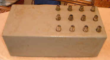
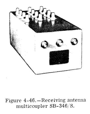
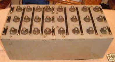
SB-346/S |
 |
antenna patch panel similar to above 3 antennas, 12 receivers Type C connectors for patch cords and antennas, Type N on rear for receiver connections. 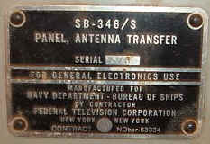 |
 |
manuf Federal Television |
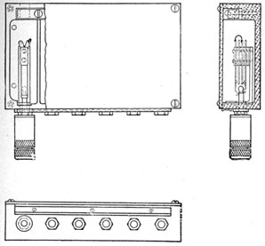
SB-346/S |
The SB-346/S consists of an aluminum case on which are mounted the upper and lower halves of an aluminum front panel (Figure 2-51). Twelve jacks are mounted on the upper half of this front panel and arranged in three vertical rows of four jacks each. Aluminum partitions in the case shield the vertical rows of jacks from one another. Three antenna input jacks are mounted on top of the case, one for each vertical row of four jacks. The top jack in the row is connected directly to the corresponding antenna jack; the remaining three jacks in the row are connected through 62-ohm decoupling resistors . On the lower half of the front panel are mounted twelve jacks which are connected to corresponding jacks on the rear of the case . Twelve UG-941A/U plugs are supplied with the unit to connect the lines from the receivers to the jacks on the rear of the case. Also supplied are twelve patch cables for connecting the jacks on the lower front panel with those on the upper front panel. |
|||
?? |
 |
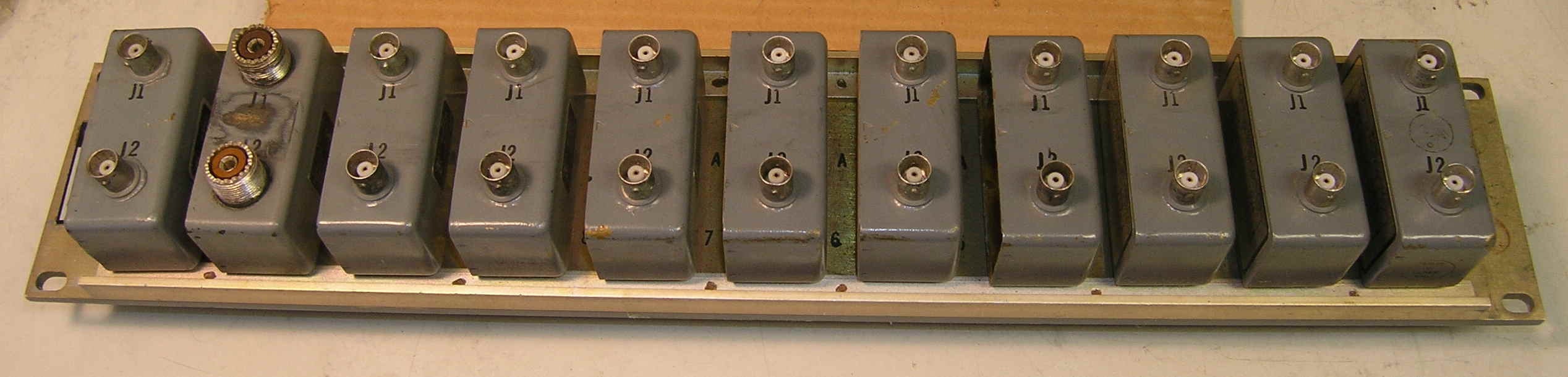
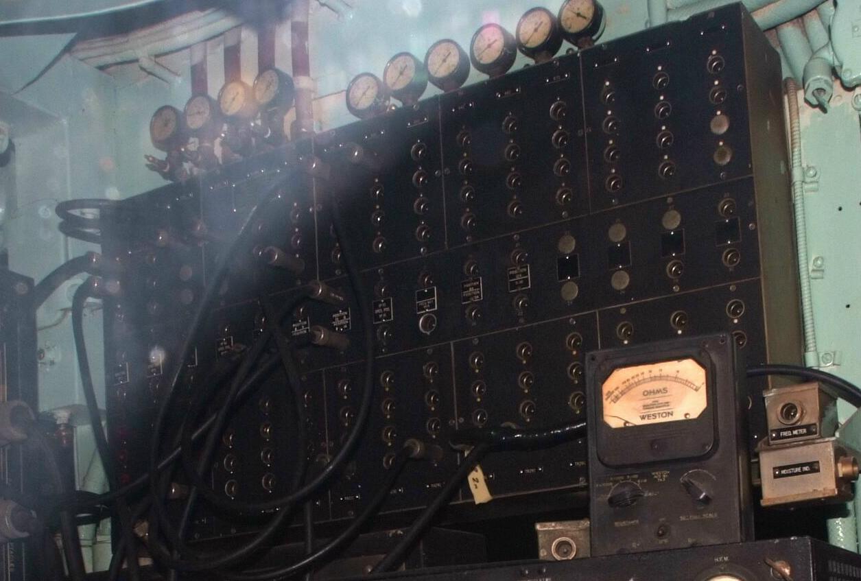
RF Jack Panel in BB-35 radio room
Six NT-49120 jacks |
==. | -- |
COMPONENTS |
||||
J-237/G |
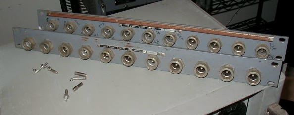 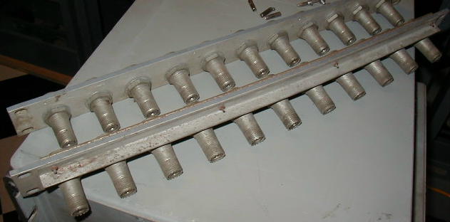 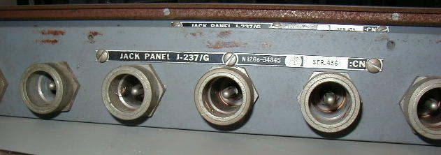 |
RF jack panel used in shore station installations - contains
eleven UG-294/U feed-through jacks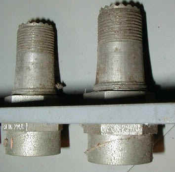
|
UG-294/U - Navy Type jack feed-through to UHF jack on
rear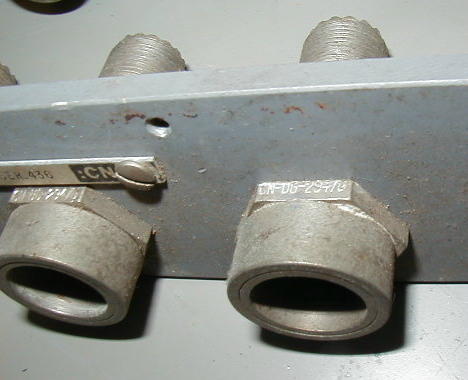
|
manuf CN - National Electrical Supply |
J-238/G |
|
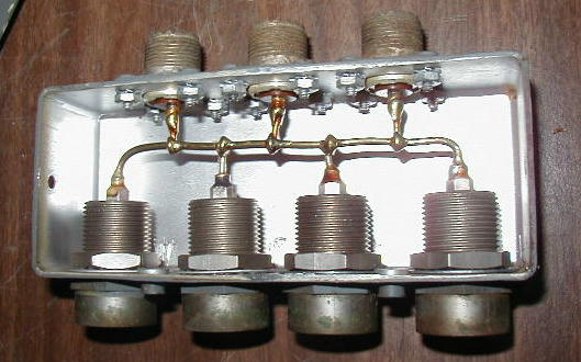
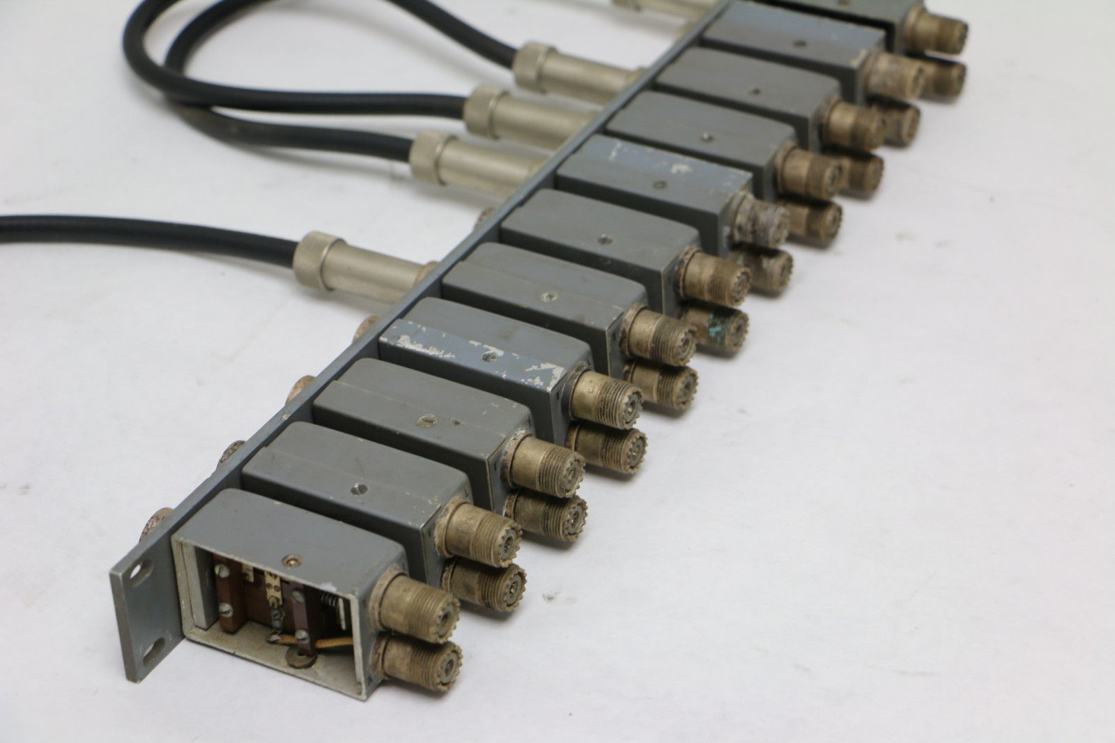
RF bridging jack panel used in shore station installations - contains
eleven NT-491729 modules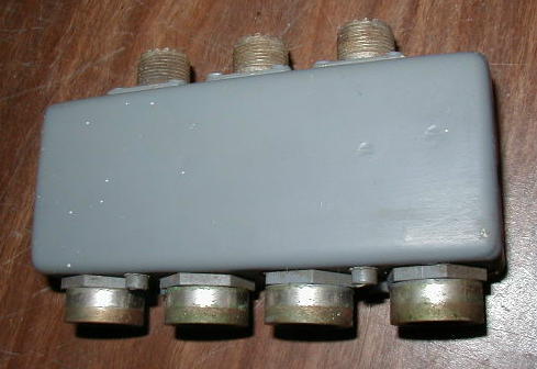 |
NT-491729 module with 4 front NT-49120
jacks and 3 rear UHF
jacks all tied together
 |
manuf CIA - Dumont Radio |
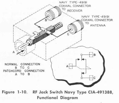
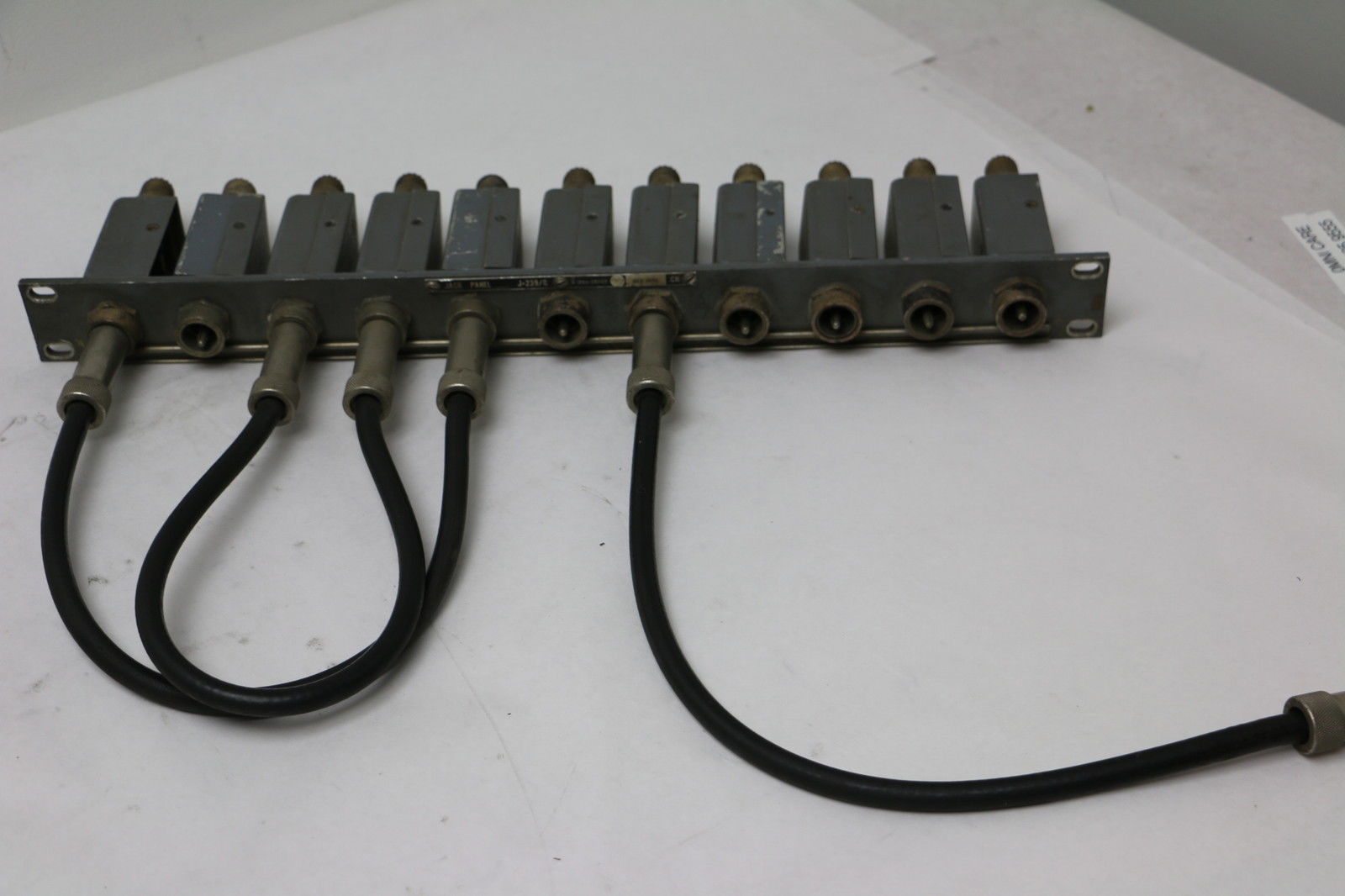
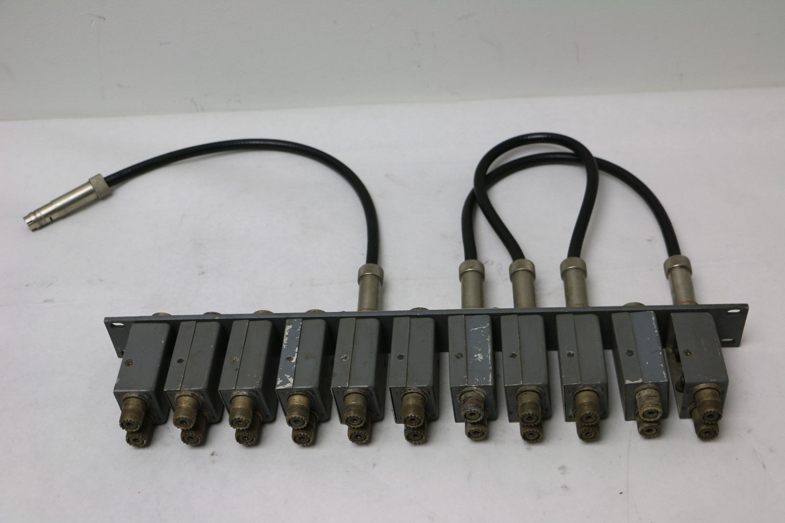
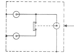
J-239/G |
|
RF switching jack panel used in shore station installations - contains
eleven NT-491388 modules 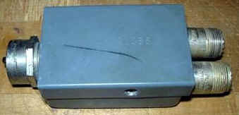
|
NT-491388 module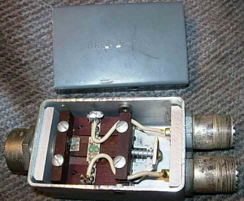 |
"Normal-Through" operation - the loop between two UHF
jacks on rear is broken when NT-49121 plug is inserted in front
jack
manuf CIA - Dumont Radio |
 |
|
 |
-- | |
NT-28006A |
need photo | Receiver Protective Device 50 or 100 watt light bulb in a cylindrical can to protect rcvr front end, |
- | - |
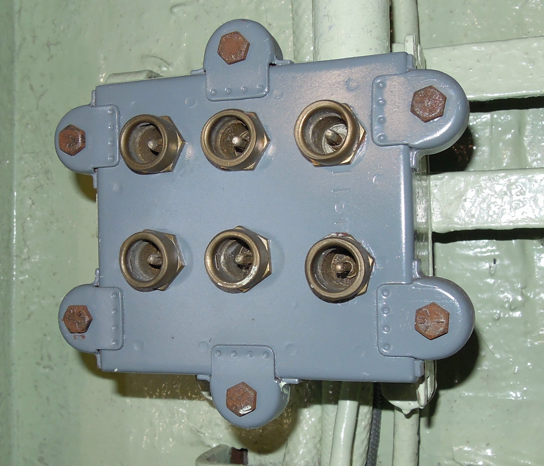
NT-49063 |
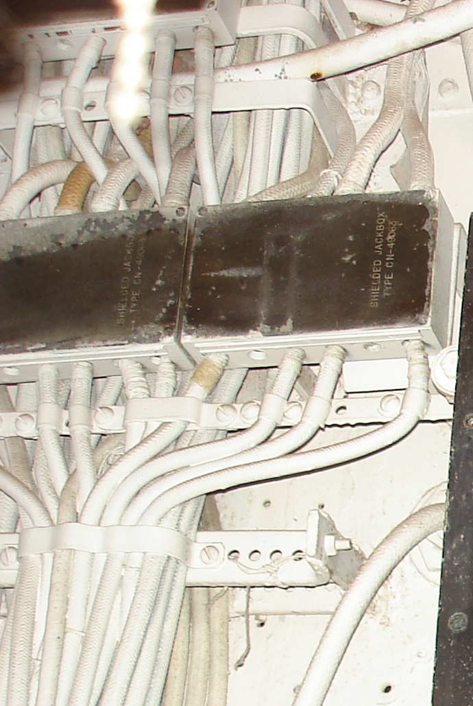 BB-35 Photo thanks to Konrad Werzner - or are these just 49063 covers used on a different junction box? |
Shielded Jackbox
|
 |
-- |
NT-49120 |
|
mating jack for NT-49121 plug | - | - |
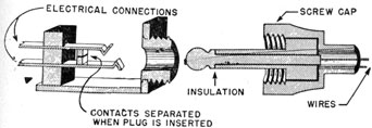
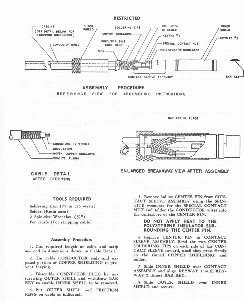
NT-49121
|
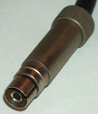 photo thanks to W7QHO Connector used for RF patch cords manuf CN - National Electrical Supply |
Type CN-49121A Antenna Plug, Navy Stock Number N17-C-71120-4869 Connector, Plug: 1 round female contact; straight type; over-all 2-7/8" long by 13/16 " diameter; RF connector; cylindrical body; brass; nickel plated; Bakelite insert; 13/32 max cable opening. 49121-A is same as 49121 except for omission of parts 7,8, and 9, and the modification of part 2 to provide a depth of 3/8" instead of 1/4" for the slots on the cable end. |
|
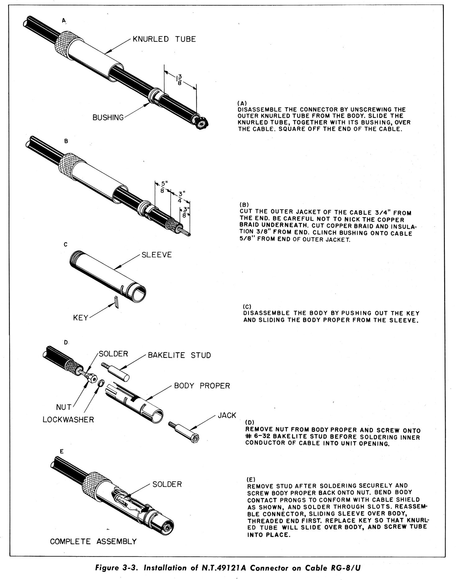 Assembly Instructions |
NT-49122
|
need photos | Patch cords using NT-94121 plugs 49122 - 18" long 49123 - 36" long 49150 - 48" long |
- | - |
NT-49151 |
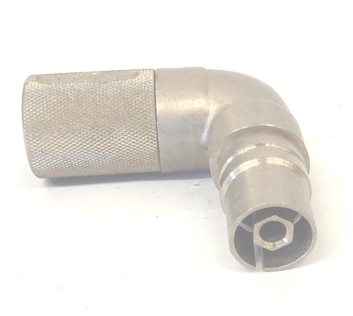 |
Right angle adaptor - one end plugs into a 49120 receptacle
and the other end receives a 49121 plug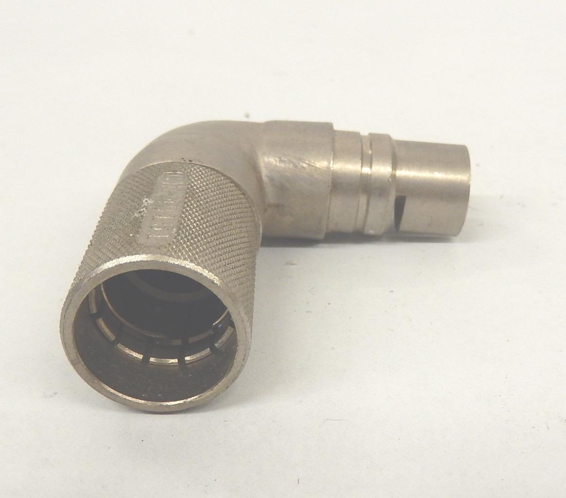 |
49120, 49151, 49121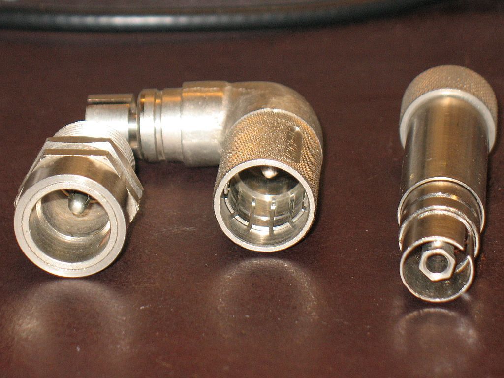 |
-- |
NT-49490 |
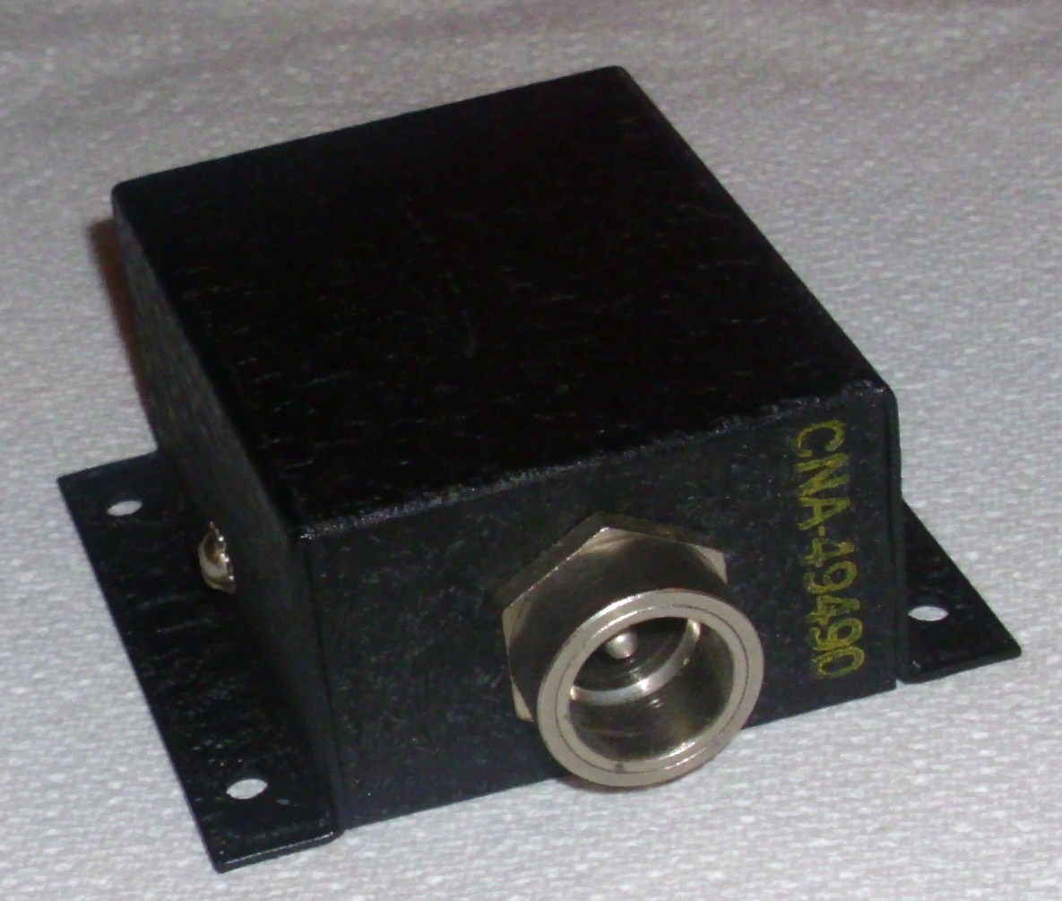 |
Adaptor to convert a receiver's antenna screw terminals to a 49120 co-axial jack | 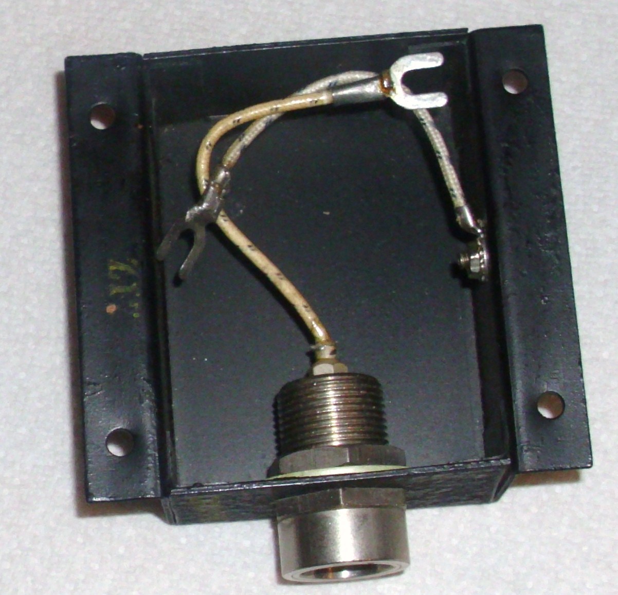 |
-- |
SA-136/G
|
SA-137/G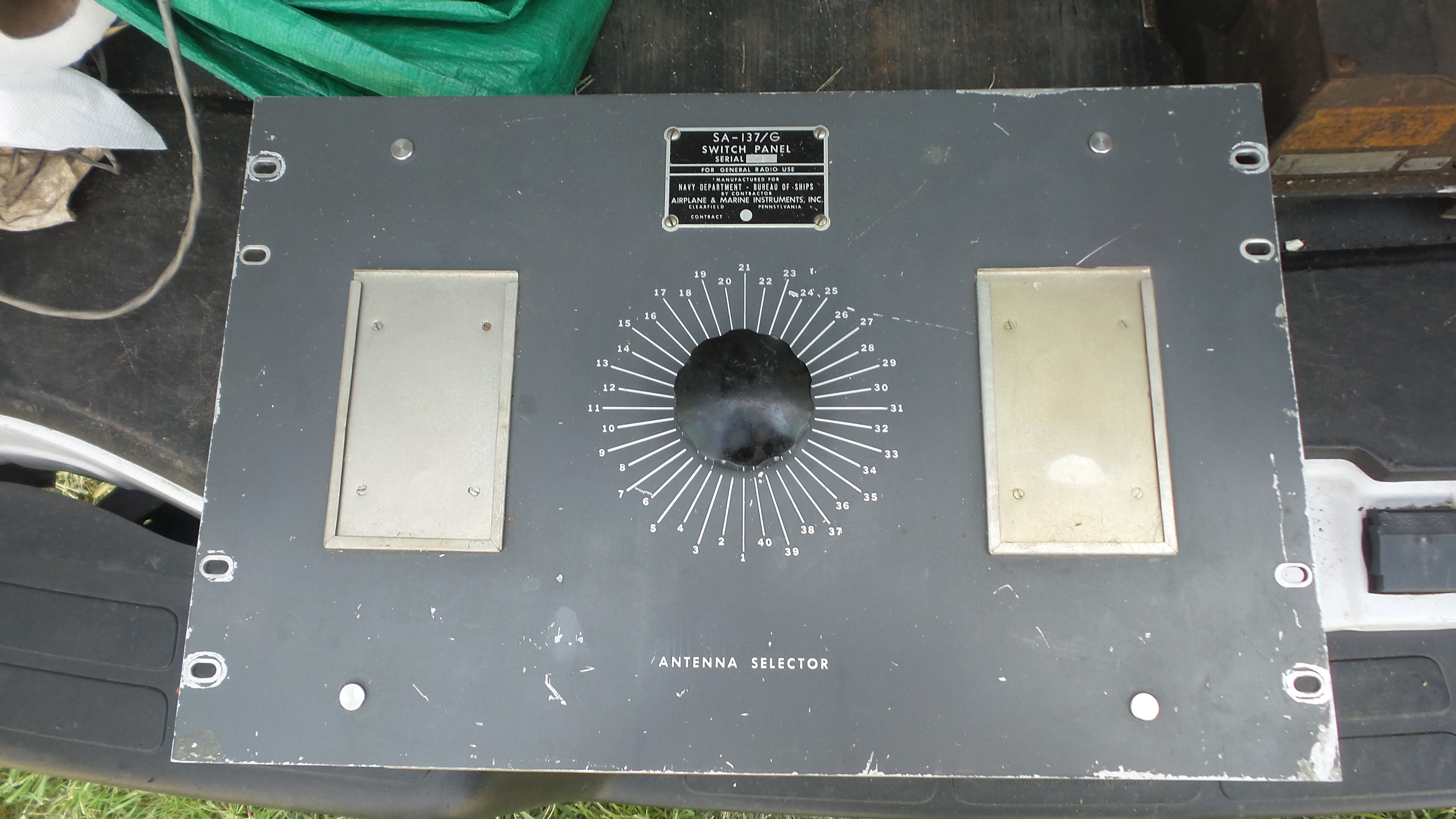 |
SA-137/G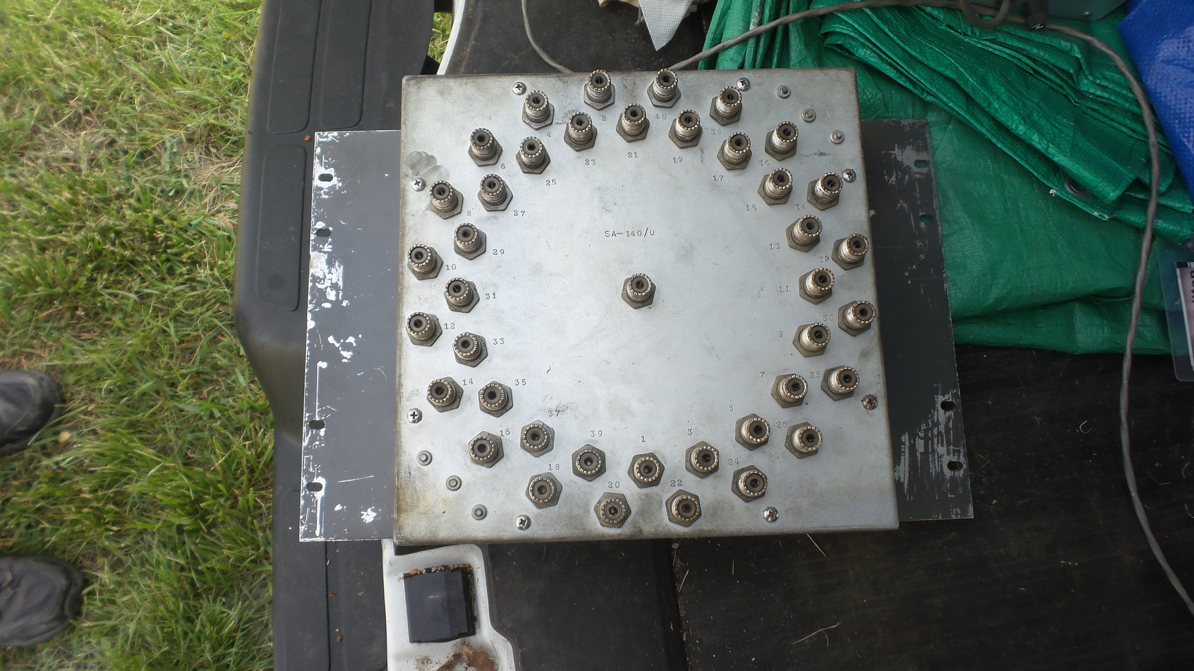 |
Manual RF switch panels used in shore station installations SA-136/G is 20 position panel SA-137/G is 40 position panel SA-138/G is 60 position panel |
- |
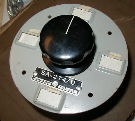
SA-274/U
|
 |
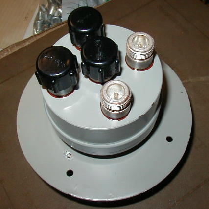 |
4 position selector switch | - |
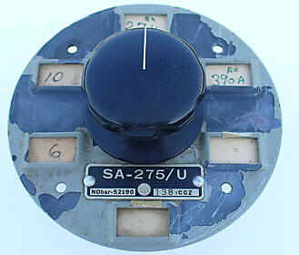
SA-275/U
|
 |
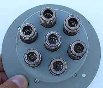 |
6 position selector switch | - |
SB-3047/BRC |
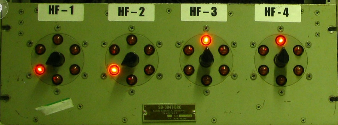 |
Submarine RF switch
Four 6-position switches with indicators |
need more info | -- |
SA-598/U |
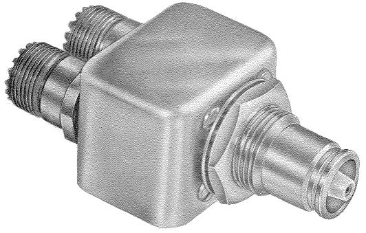 |
switching jack module - replaces NT-491388 in J-239/G but
with TMC QDS front panel jacks
Note - Mating plug is UG-968/U |
 |
manuf TMC model SW-195 |
SB-931/U |
need better photo |
replaces J-237/G panel but with eleven TMC QDS front panel jacks | QDS on front, UHF on rear | manuf TMC model QDP-411A |
SB-932/U |
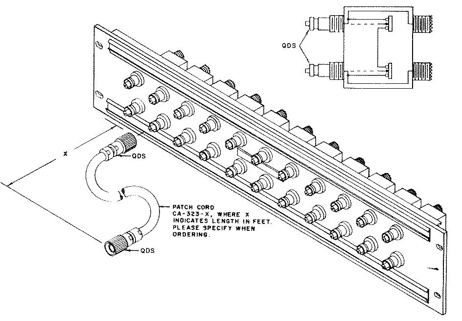 |
RF switching jack panel used in shore station installations
- eleven modules - replaces two J-239/G - uses two TMC QDS jacks on front and two UHF jacks on rear |
Dual "Normal Through" - the loop between two UHF jacks on rear is broken when QDS plug is inserted in either front jack | manuf TMC model SPP-3
|
TMC SPP |
like SB-932/U but with BNC jacks on rear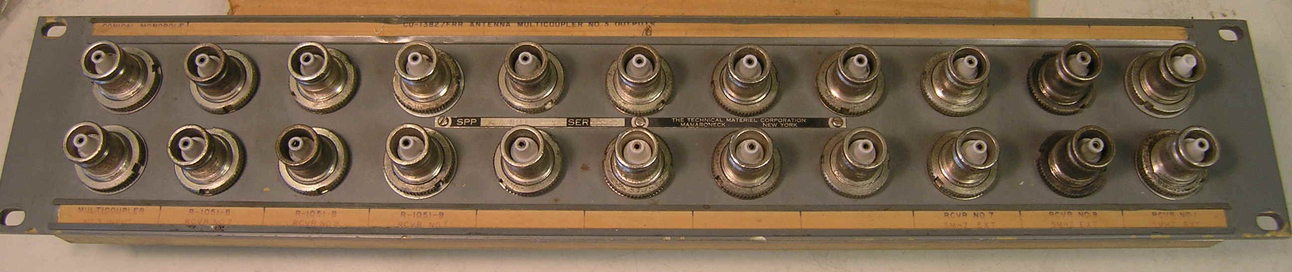 |
Rear (with one UHF-connector module) |
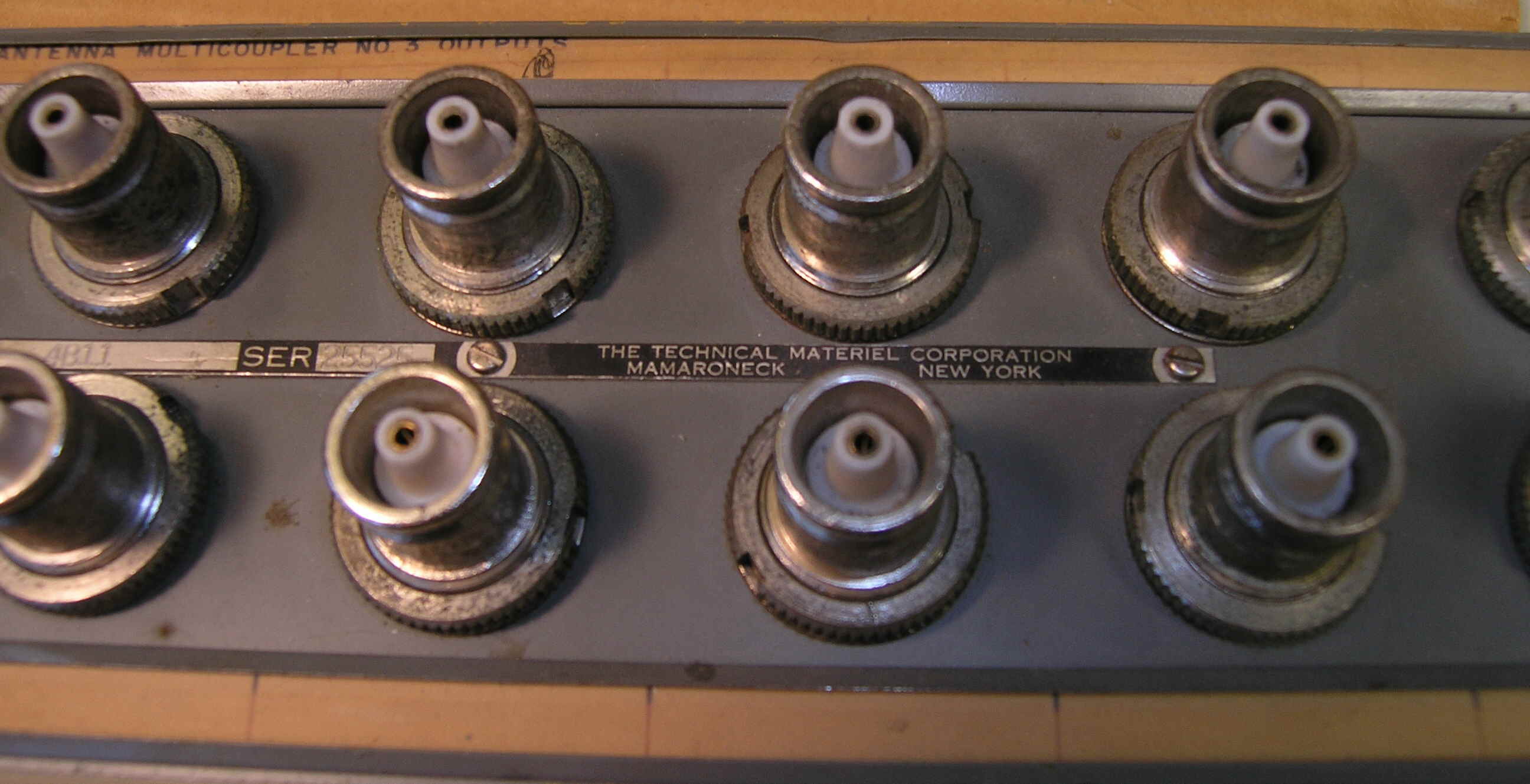 |
manuf TMC model SPP |
TMC SW-224 |
Dual "Normal-Through" modules used in SPP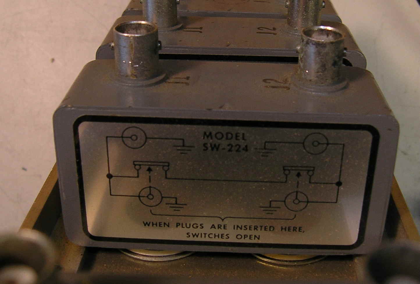 |
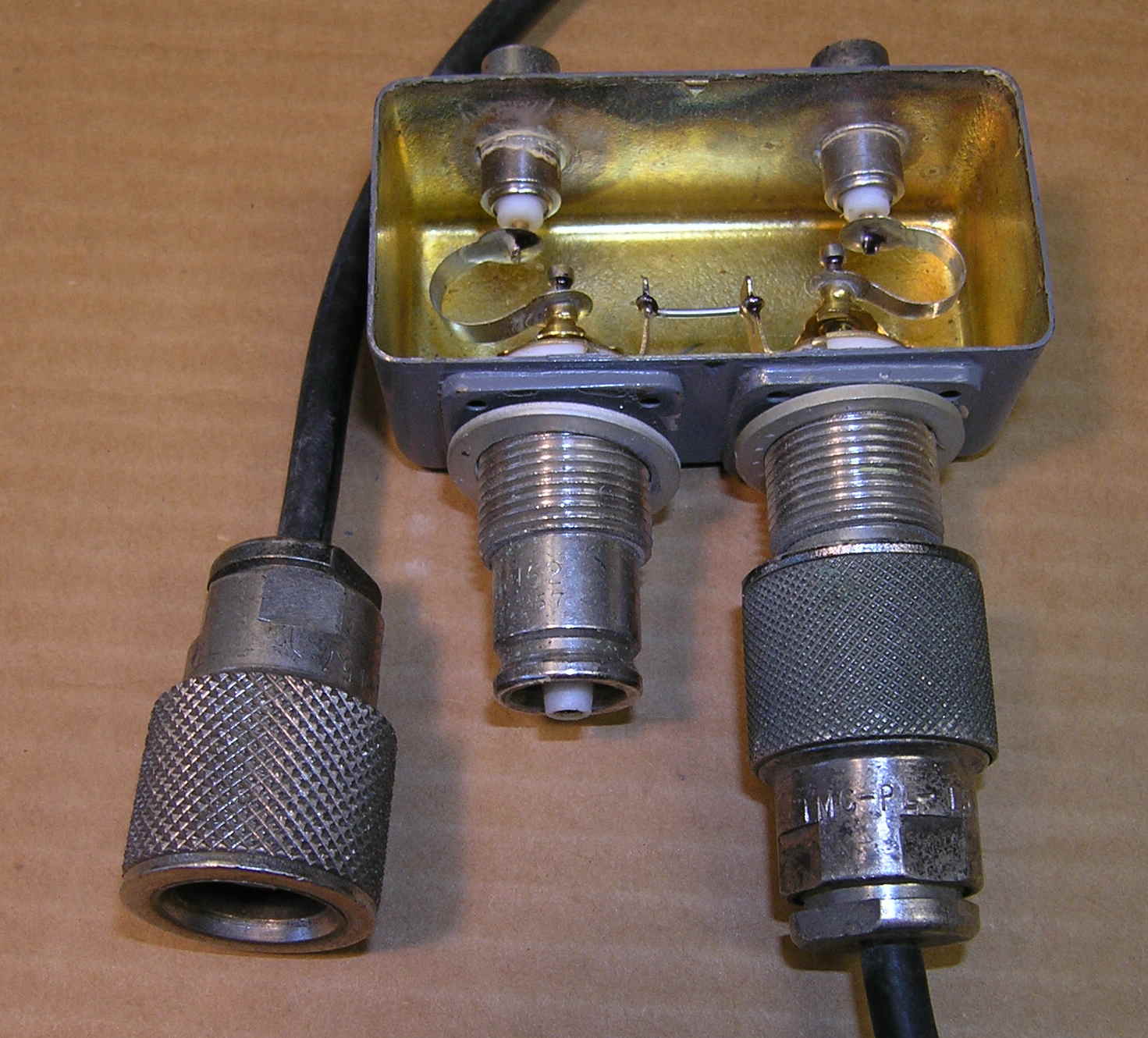 |
Plug not inserted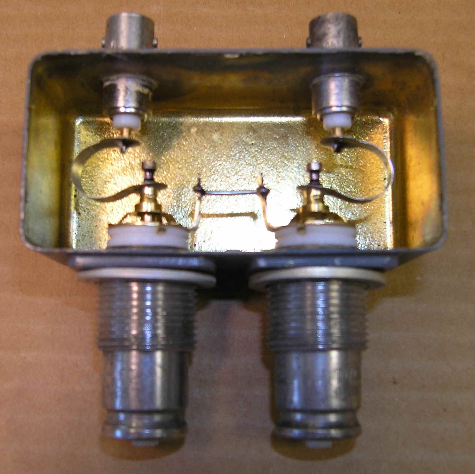 |
Plug inserted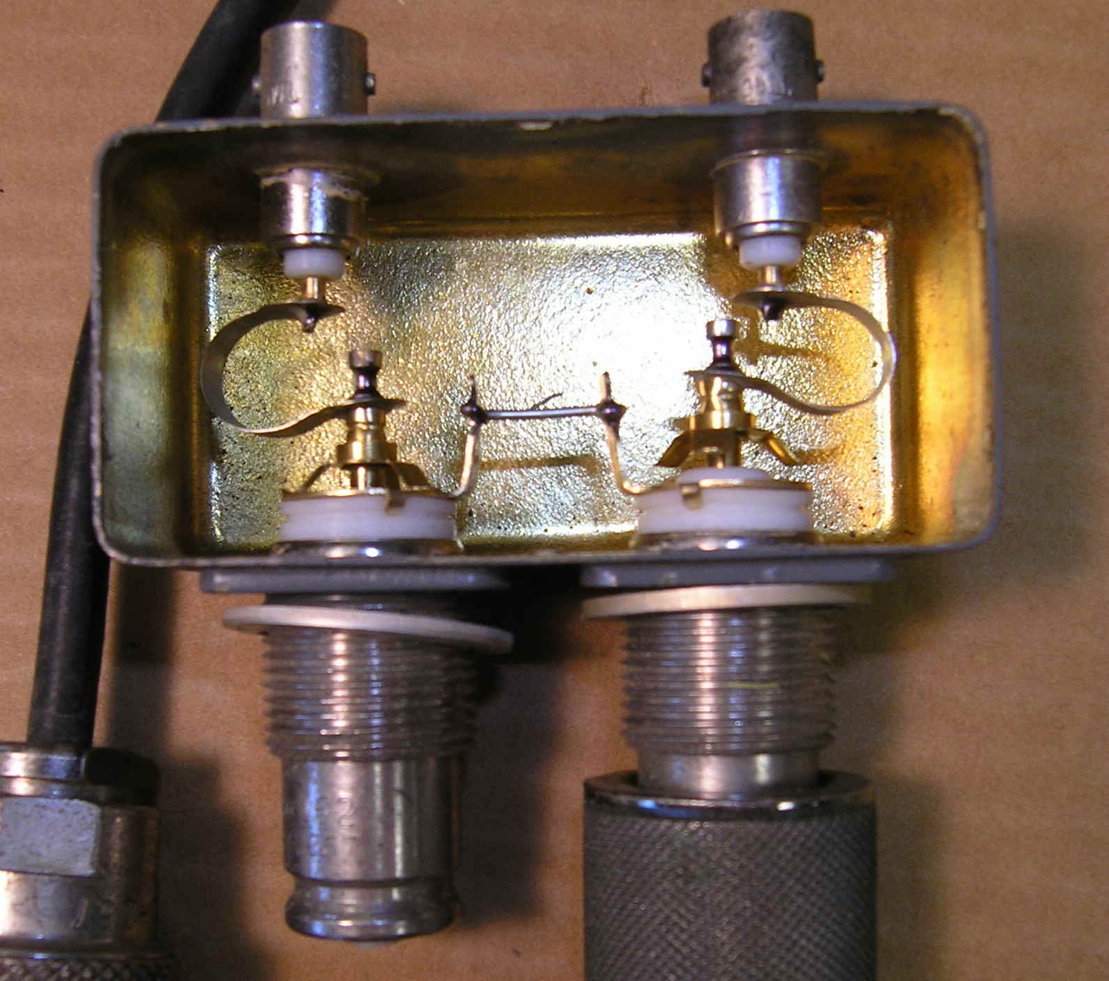 |