NAVFACENGCOM N62470-92-D-8965 "Navy Cold War Communication
Context: Resources Associated with the Navy's Communication Program
1946-1989" (1997)
Survey of properties and facilities
Table of contents
and pdf download
NAVELEX 0101,102 "Naval Shore Electronics Criteria: Naval
Communications Station Design" (1971)
COMMSTA design manual
Table
of contents and pdf download
NAVSHIPS 92675 "Handbook of Naval Shore Station Electronics
Criteria" (1956-60)
Table of
contents and pdf downloads
Below are some selected interesting figures
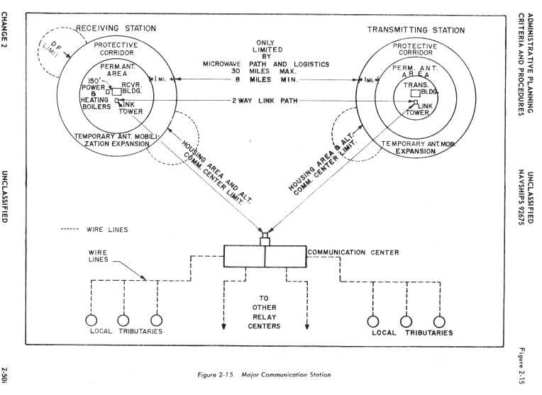
major comm station layout
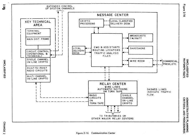
comm center functional and traffic flow diagram
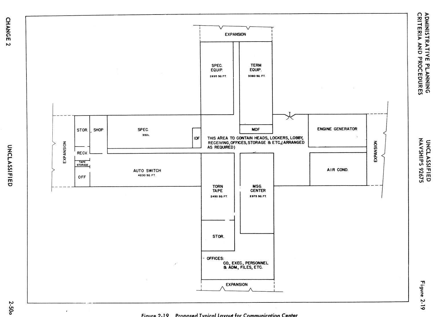
typical room layout for comm center
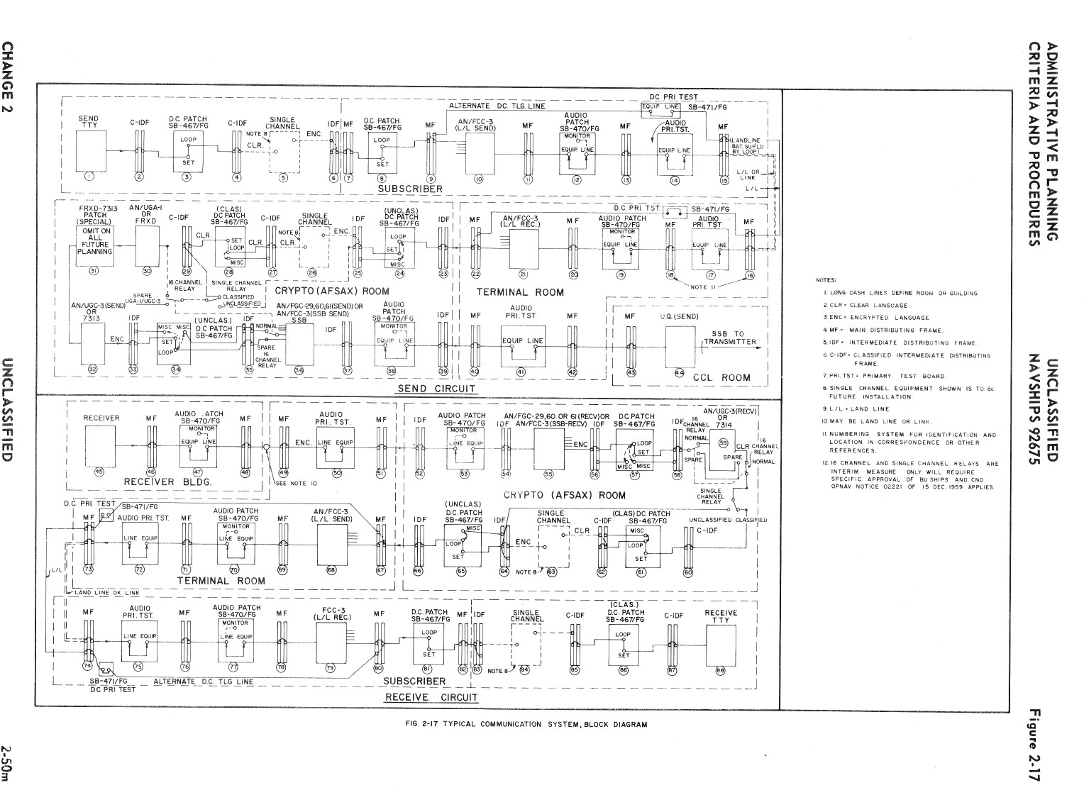
communications system block diagram
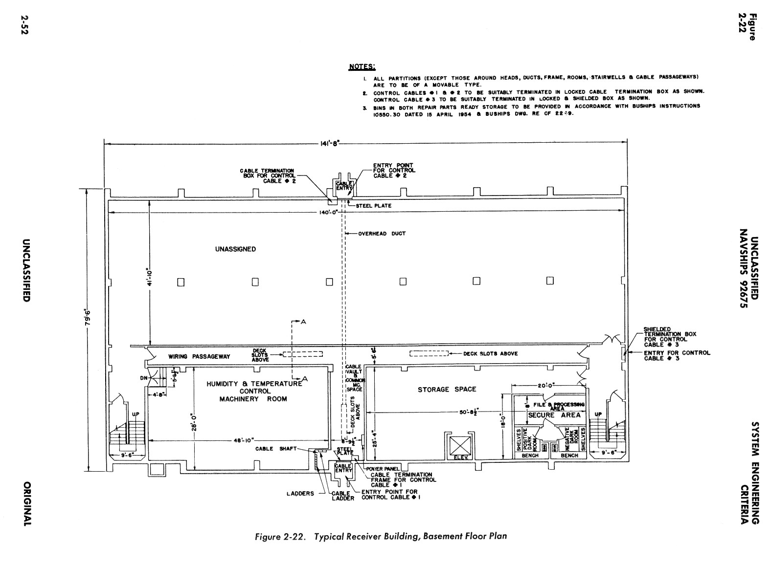
receiver building, basement floor plan

receiver building, first floor plan
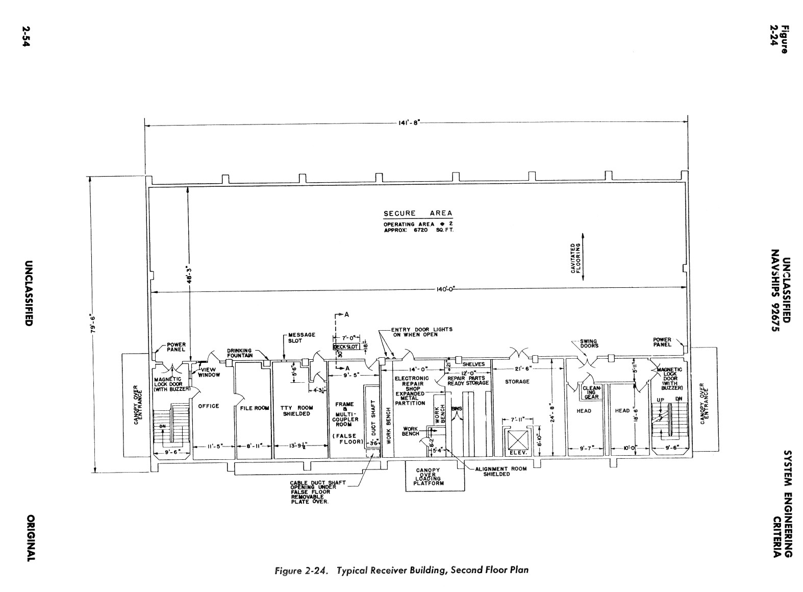
receiver building, third floor plan
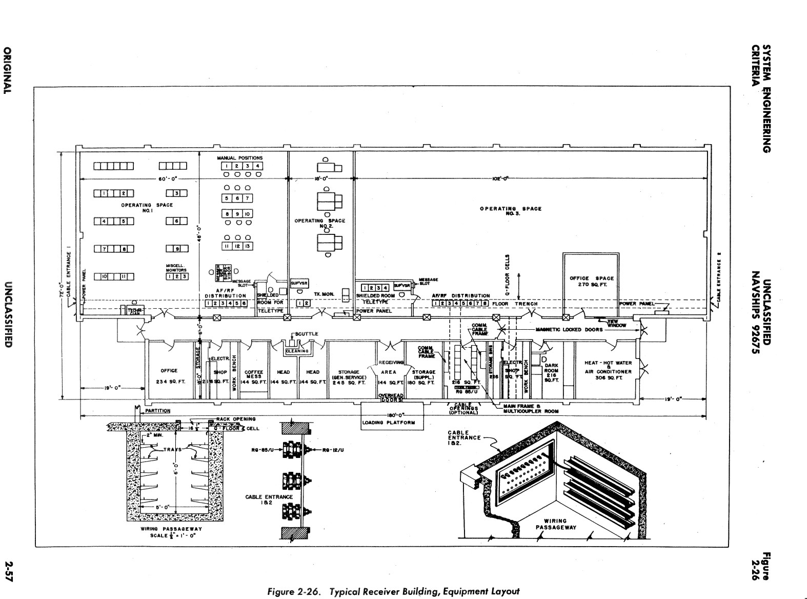
receiver building, equipment layout
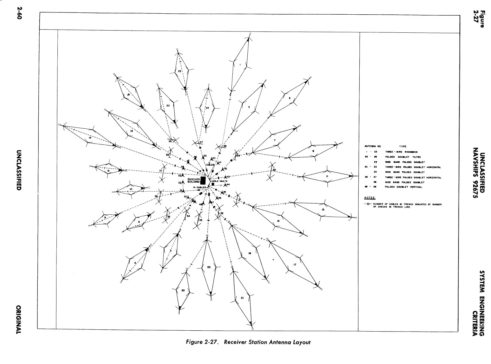
receiver site antenna layout
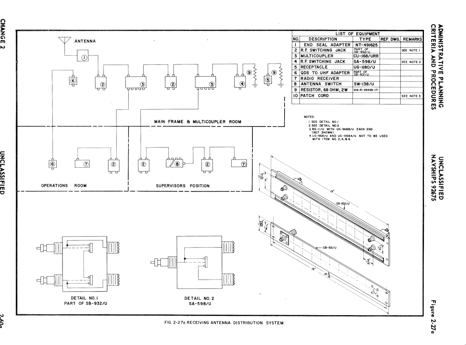
receiving RF distribution system

DC primary test board SB/471/FG
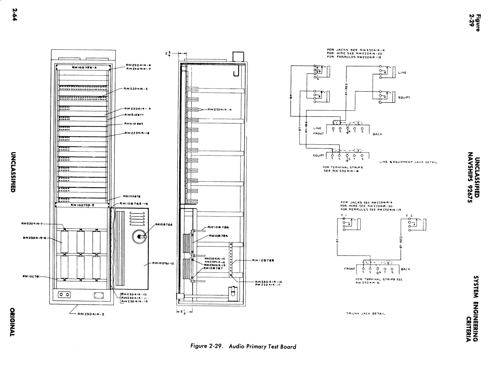
AF Primary Test Board
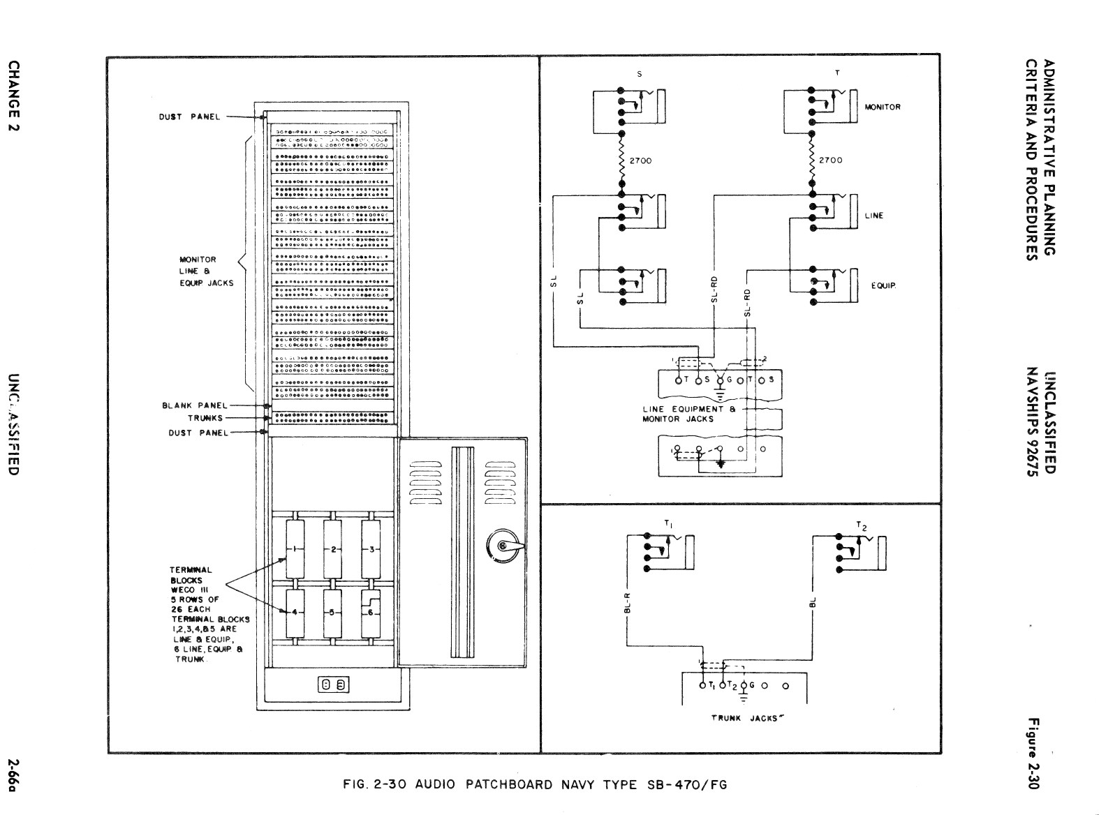
AF Patchboard SB-470/FG
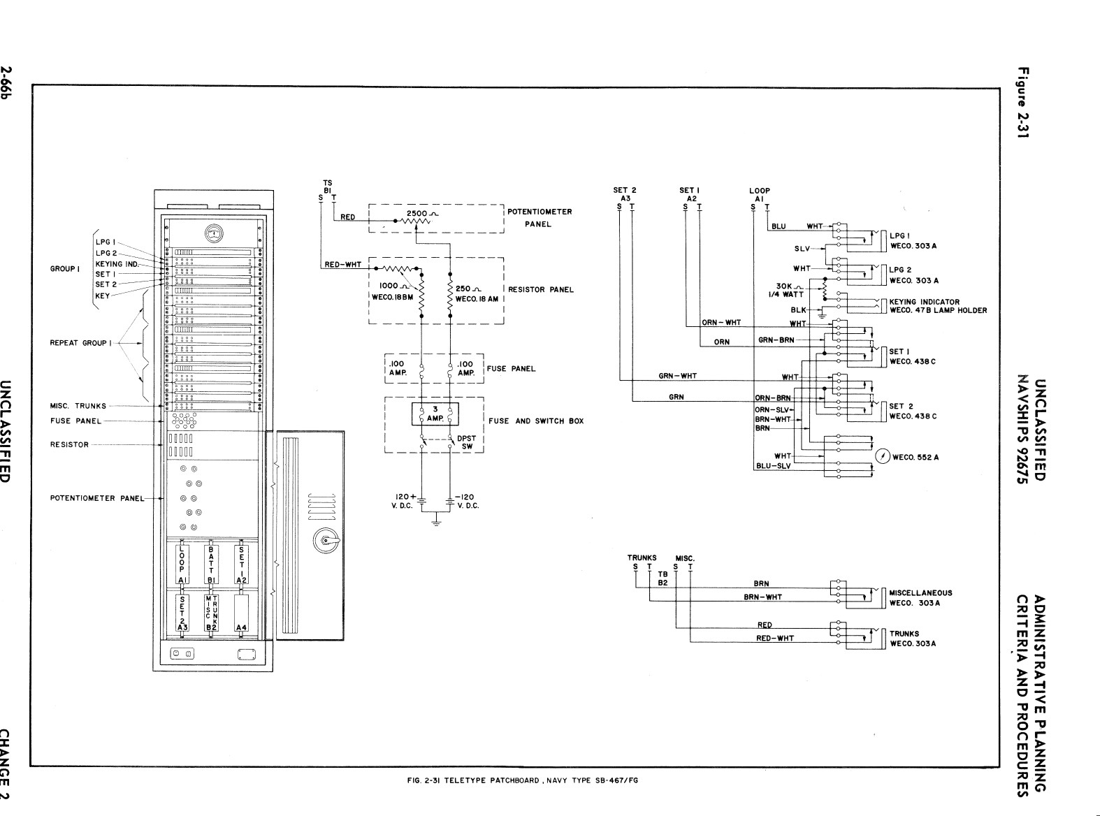
TTY Patchboard SB-467/FG
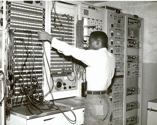
Patchboards at NAVCOMMSTA Guam - Note AN/FCC-3 multiplexer in Rack #14 and TH-39/UGT keyer in Rack #15
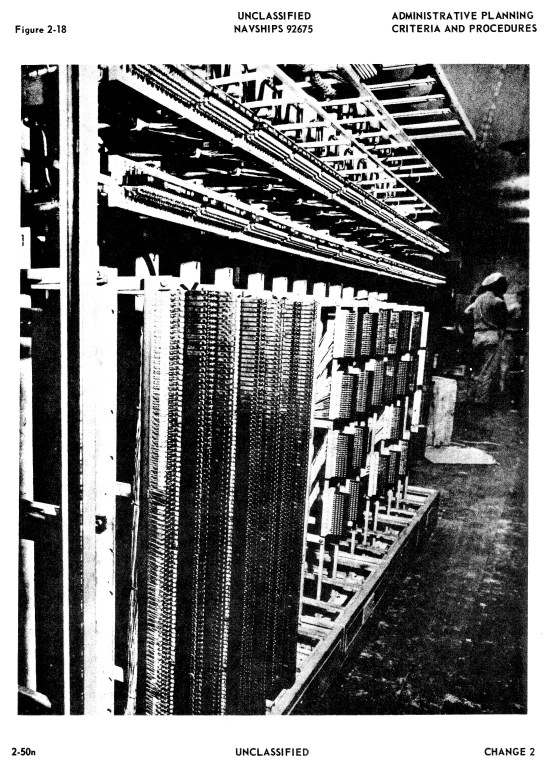
MDF - Main Distribution Frame - terminal blocks
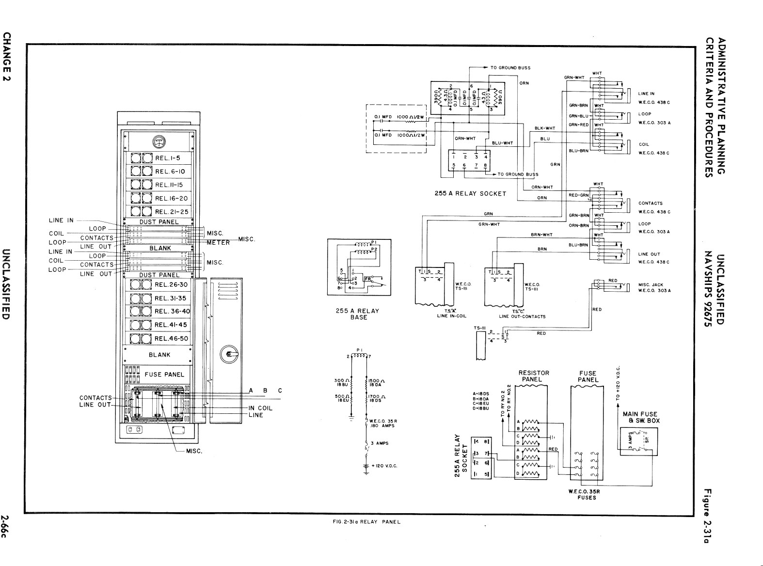
Relay Panel
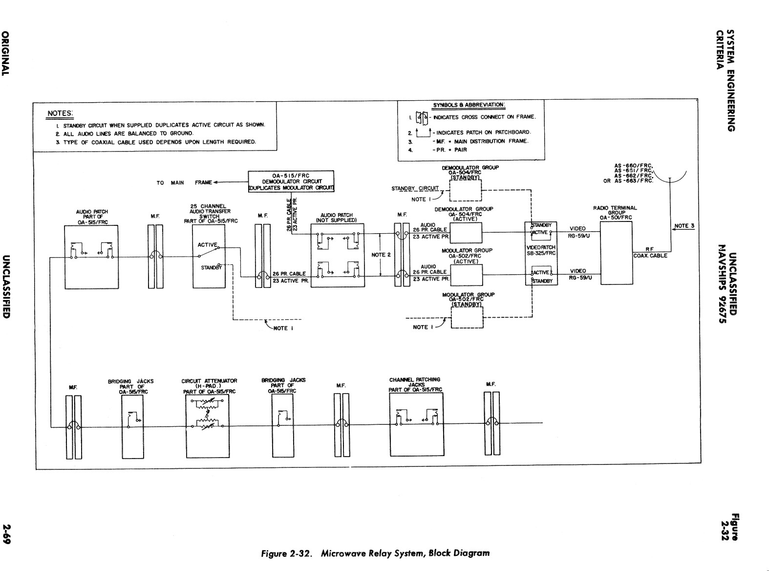
Microwave Relay System Block Diagram (used to communicate with Transmitter and Receiver sites)
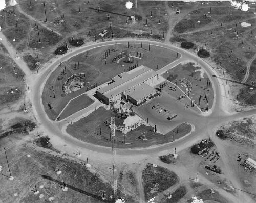
Fig 1-2 Transmitter building & antenna switchyard (Guam)
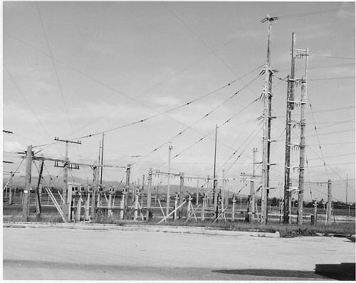
Transmitter antenna switchyard (Guam)
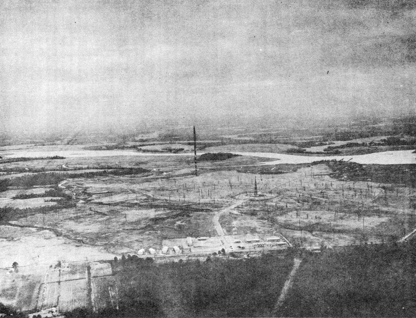
Fig 2-20 Transmitting Station
2-50q - transmitter building design
2-50s - transmitter building design
2-50t - transmitter building design
2-50u - transmitter building design
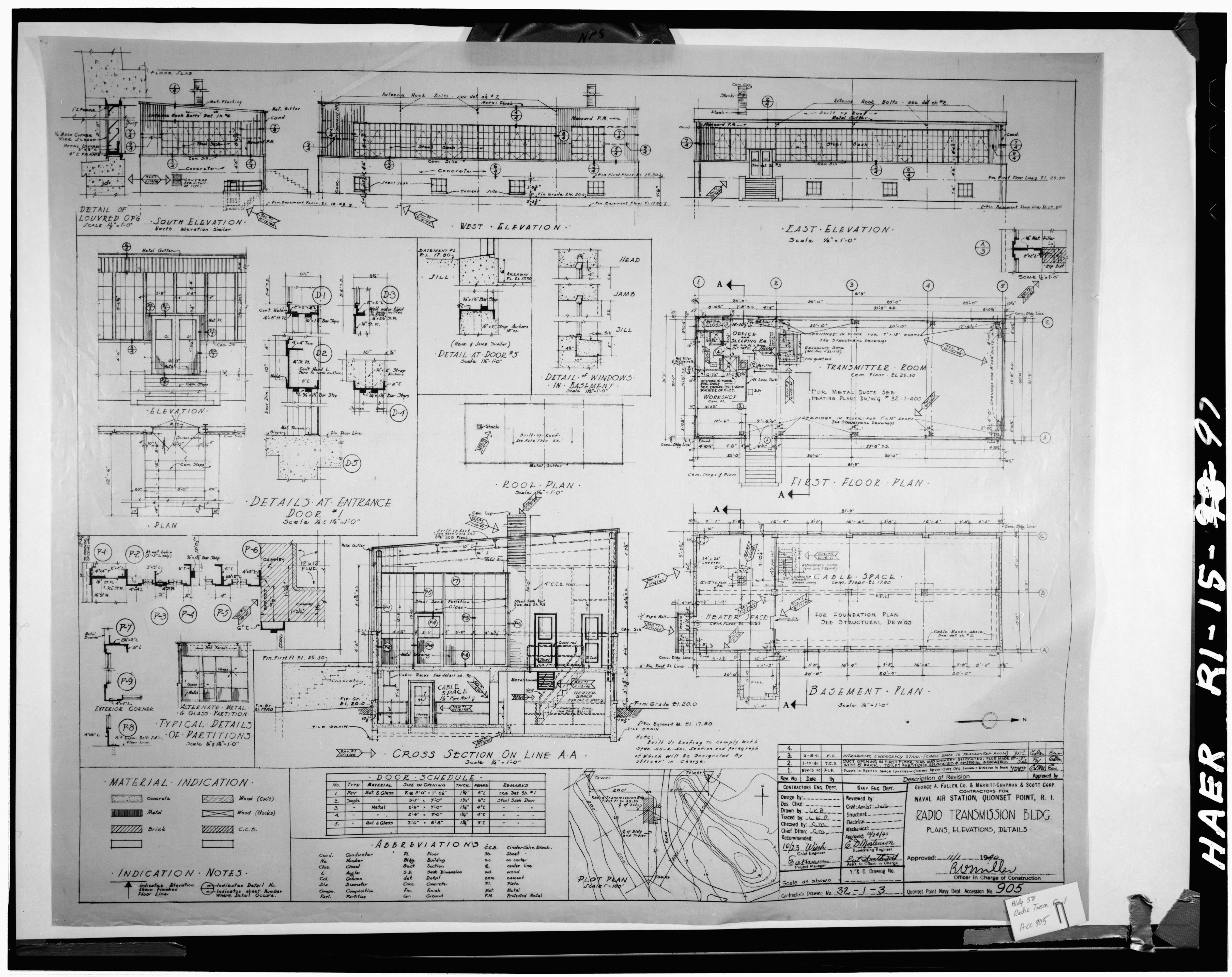
Quonset Pt. Transmitter Building (1940)