The transition from the international Morse code keying transmission system to
the automatic teleprinter system came about much later on the very-low-frequency
circuits than on those in the high-frequency band, This was primarily due to the extremely low bandwidth characteristic of the huge shore station antennas at the very-low
frequencies, which imposed a limit on the speed of transmission (20 words per minute,
continuous wave, international Morse code keying) to about one-half that required for
teleprinter operation at its lowest speed. In overcoming this limitation, NRL devised
the first teleprinter system providing effective operation on the very-low-frequencies
(1951) . The performance of this system was demonstrated in operations using
transmissions from the Navy's VLF station at Annapolis, Maryland (NSS, 15.5 kHz) over long
distance circuits to Iceland, England, Panama, Canal Zone, and North Africa. This system
was self synchronizing and provided the encoding of a standard teleprinter
signal into a four level signal having one half the keying rate of the original, The transmitter
was shifted through the four frequency levels by the encoded signal which, as modified, could then be
accommodated by the bandwidth of the antenna, At the receiver, a decoding device converted the received four level signal back into its original
form for operation of the teleprinter. A novel, stable, regenerative circuit
provided a much higher degree of selectivity in the frequency-shift receiver than had previously
been attained (25 Hz bandwidth), A specially designed discriminator permitted segregation
of the signals on the four frequency levels, which were separated by a very small difference in frequency (4 Hz).
With the advent of the Polaris weapon system, grave concern arose
regarding the reliability of command and control communications via the Navy's VLF
transmitting system. In responding to this situation, NRL developed a VLF facsimile transmission
system which was first to provide reliable command and control communication from a
single high power transmitting station in the United States to continuously submerged
submarines when operating in any critical world area (1959). Early in 1959, the submarine
USS KATE used the system successfully on its trip to the North Pole, The
submarine USS TRITON, in accomplishing the first circumnavigation of the globe, submerged,
used the system throughout the voyage with good results (February-May 1960). The system
was installed on all Polaris submarines and provided highly reliable command-control
communications during the critical period that followed, This system became known
as "Bedrock". The Navy's existing transmitting system had to contend with high atmospheric
noise levels prevalent at the very low frequencies which produced low signal to noise ratios and seriously affected the reliability of communications in distant
areas of operational importance, such as the Mediterranean Sea, In the system devised,
the superior performance obtained under extremely low signal to noise ratio conditions
was achieved through the use of very narrow frequency bandwidth transmissions and the
redundancy provided by facsimile type signaling, A facsimile-controlled exciter provided the small frequency shifting of the
transmitter. The frequency-shift receiver utilized the novel techniques for high selectivity and discrimination previously devised
for the VLF teleprinter system, Transmitter components were provided for installation
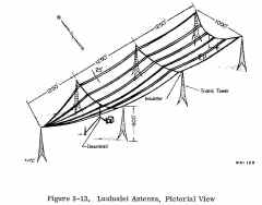
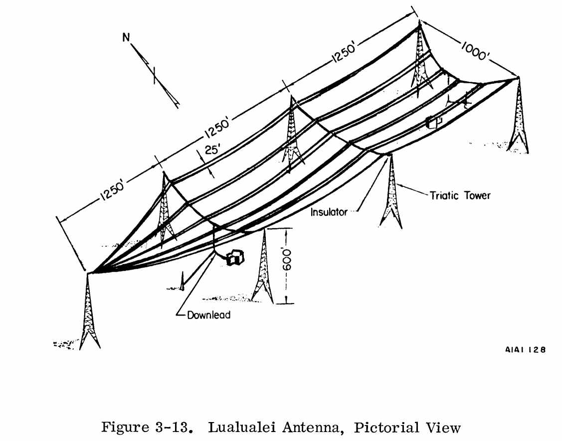
at shore stations: NSS, Annapolis, Maryland; NAA, Cutler, Maine; NPM, Lualualei, Hawaii;
NPG, Jim Creek, Washington; and NBA, Summit, Panama Canal Zone (1958-1964). Receiver
components were supplied for submarines, the first installation being made on the USS
SABLEFISH (January 1959) . In the trials of the system made with this submarine in the
Mediterranean Sea area, excellent submerged reception results were obtained on transmissions
from the station at Annapolis, Maryland. Similar results were obtained by the submarine
USS BANG at its station in the North Atlantic off Norway (February 1959).
NRL developed a frequency-shift keyer which for the first time permitted automatic operation of the Navy's VLF transmitters at a rate as high as 60 words per minute with a high degree of reliability for command-control communications to Polaris submarines (1963) . All of the Navy's high power stations were then equipped with these keyers.
The system utilized two frequency levels for keying with provision to avoid the large voltage and current transients previously experienced when the large quantity of oscillatory energy in the antenna system was abruptly changed in frequency. These transients had, at times, caused a flashover of "horn-gaps" and other protective devices followed by objectionable shutdown of transmitters due to overload. In certain instances, critical damage occurred, such as the burnout of antenna loading inductance cable, rendering the station inoperative for a considerable period. The transients were avoided by beginning each successive "mark" and "space" frequency shirt at the zero-crossing points of the "mark" and "space" frequencies, when these points were coincident in phase, and arranging the rate of change of frequency to be linear during the transition process. The transition period was of such length as to hold the sideband energy generated during transition within the frequency bandwidth of the antenna, Maximum utilization of the antenna bandwidth was obtained by very precisely maintaining the "mark"
and "space" frequencies; this was possible with NRL-devised techniques. Full utilization of the antenna bandwidth and confinement of the sideband energy to within its limits are major factors in maximizing the rate of transmission,
The system permitted changes in the transmitter frequency to be made quickly and easily. Frequency-shift keyers of this type were
provided for the Navy's VLF stations at Cutler, Maine (NAA); Jim Creek, Washington
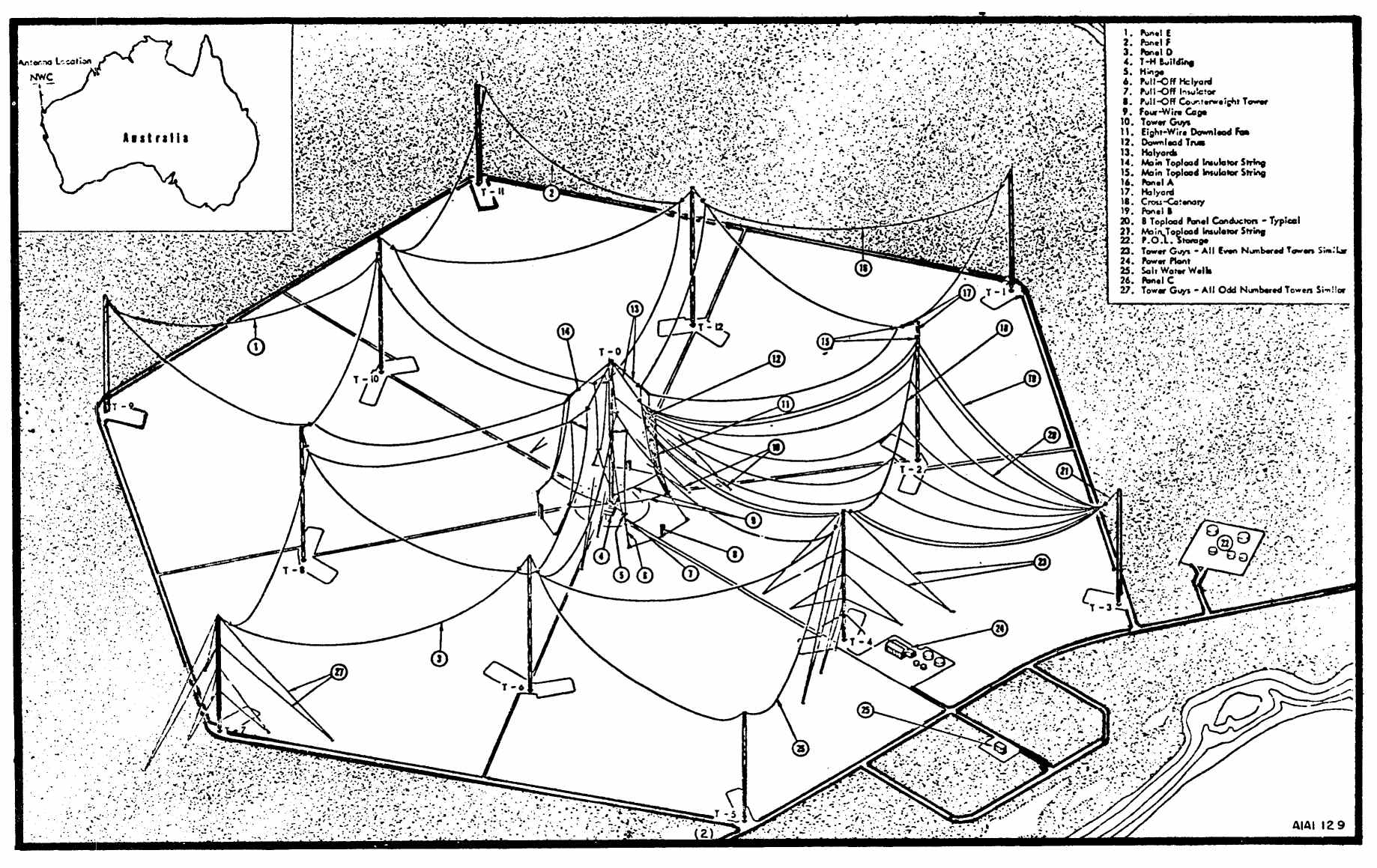
(NPG); Lualualei, Hawaii (NPM) ; Northwest Cape, Australia (NWC); and Summit,
Panama Canal Zone (NBA) (1966) , During 1970, Annapolis, Maryland (NSS) and Yosami, Japan
(NDT) were equipped.
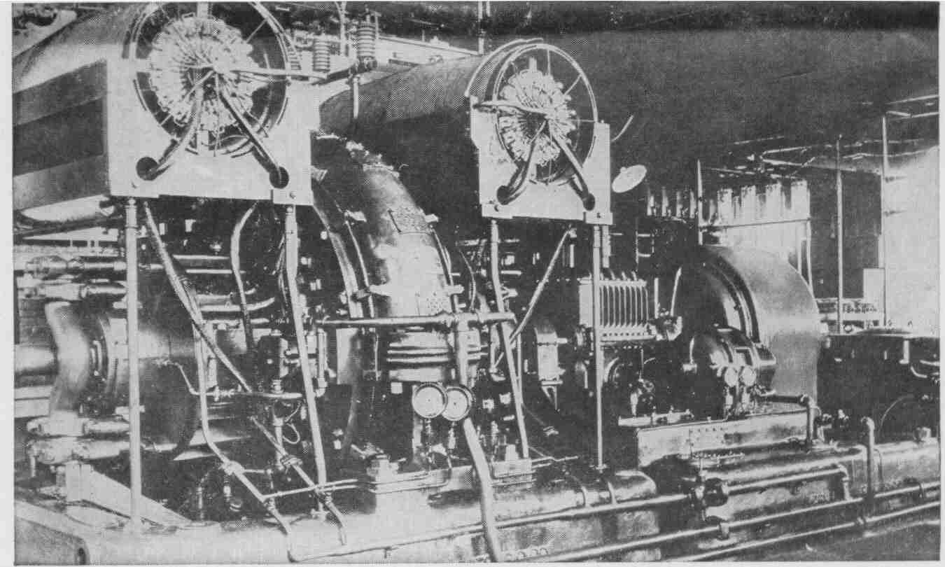
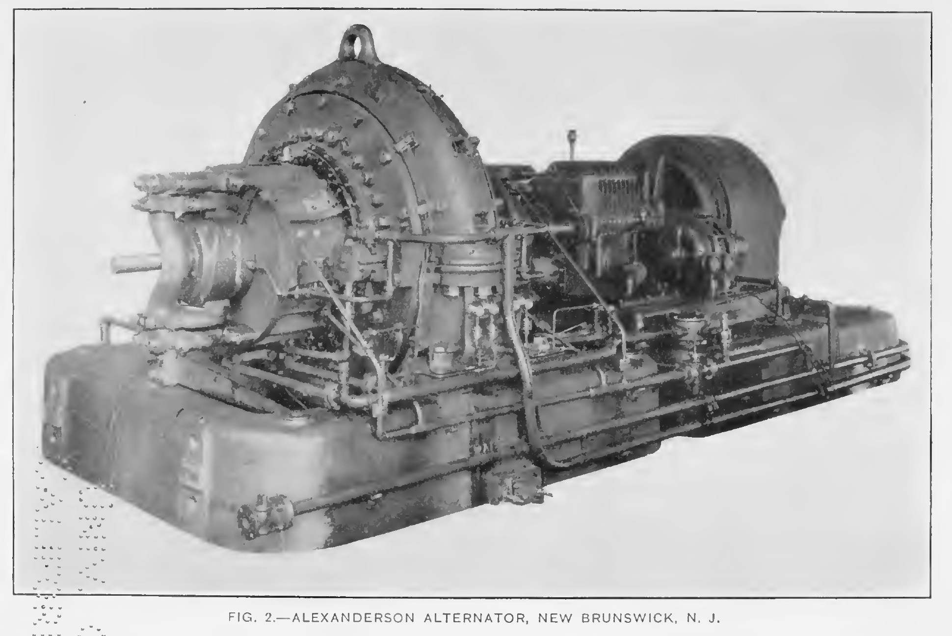
| Alexanderson Alternator
In use by USN at several sites from 1918-1948
Surviving
transmitter at SAQ, Sweden
|
200kw, 12.5-28.57 kc
Good History Article |
NFF- New Brunswick - 200kw Alexanderson
alternator
|
NFF- New Brunswick - 200kw Alexanderson
alternator

|
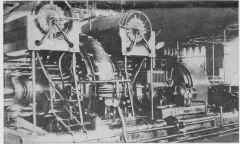
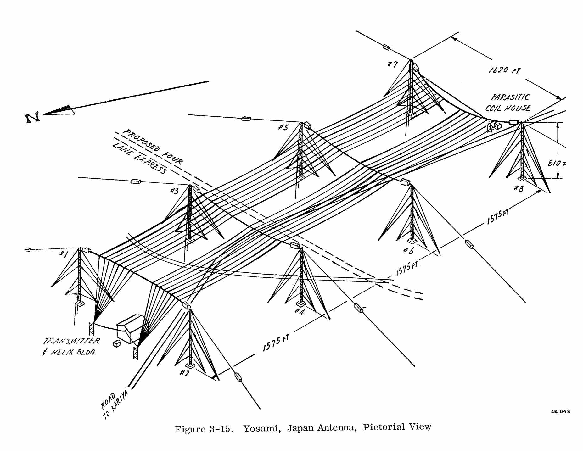
Telefunken 500 KW Rotary Generator
 |
500 KW, 17.442 kc
Yosami Japan
|
installed 1929 at Yosami Japan
USN use 1950-93
replaced by AN/FRT-64?
need more info about this
|
 |
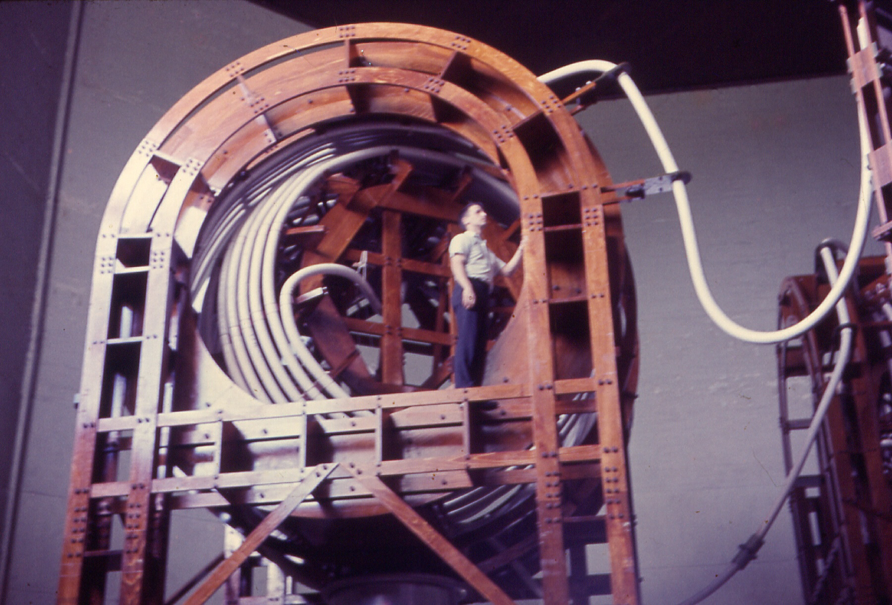
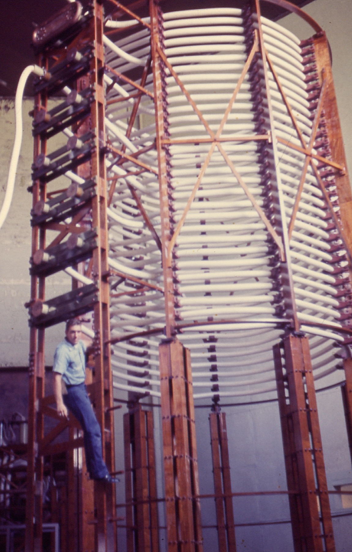
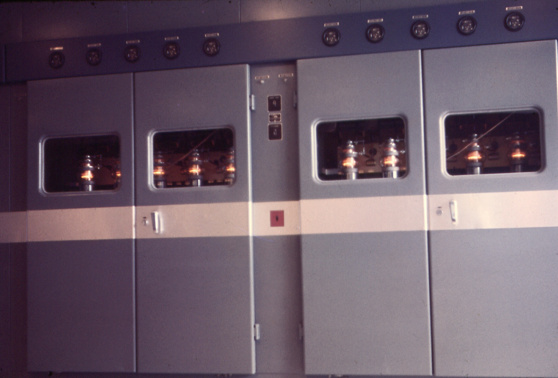
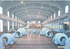
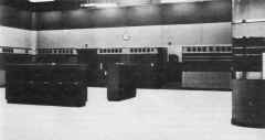
| TAW, TAW-a
Installed at Lualualei (Hawaii) and Cavite (Philippines)
|
TAW 300kw, TAW-a 500kw, 16.6 kc
Using fifty 10kw tubes
1958 photos here |
Lualualei TAW-a was replaced by AN/FRT-64 in 1964
Cavite TAW-a was presumably destroyed in 1941 attacks.
|
-- |
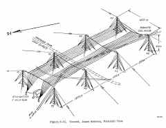
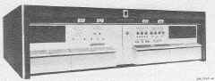
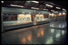
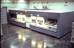
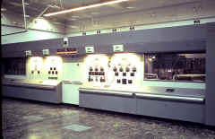
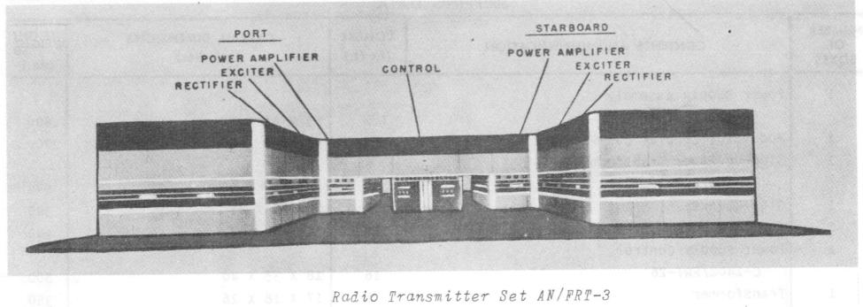
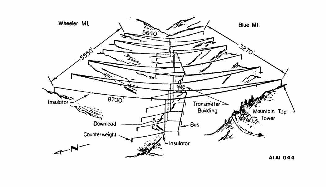
AN/FRT-3
NAVRADSTA(T) Jim Creek Page with photo articles
on transmitter and antennas
|
1400 kw VLF 24.8kc - RTTY & CW
 |
installed at NLK Jim Creek WA
manuf by RCA
|
 |
|
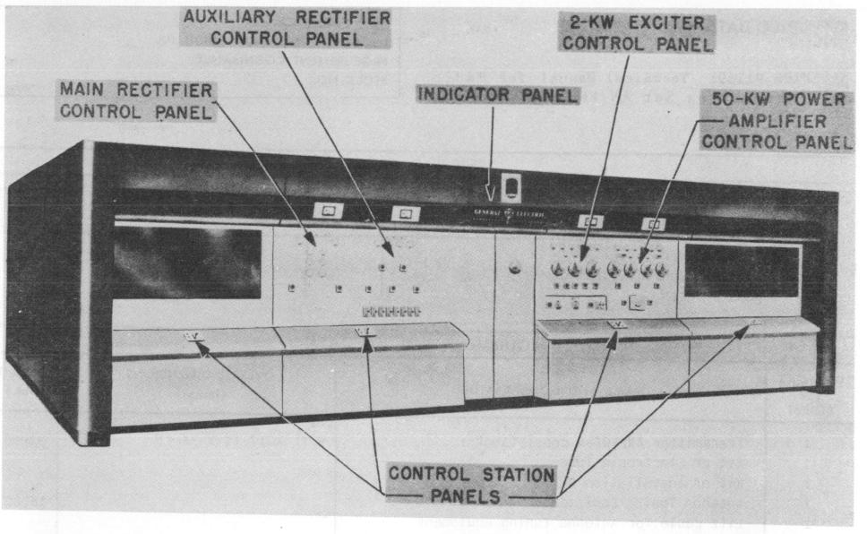
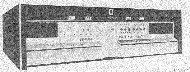
AN/FRT-4
|
|
55 kw LF 50-150 kc
similar to TCG-2 except air-cooled
|
spec
sheet
manuf General Electric
NAVSHIPS 91169 |
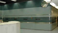
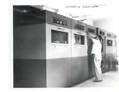
AN/FRT-4 at Buskin Lake
 |
AN/FRT-4 at Buskin Lake
 |
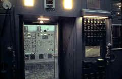
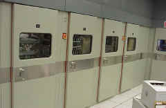
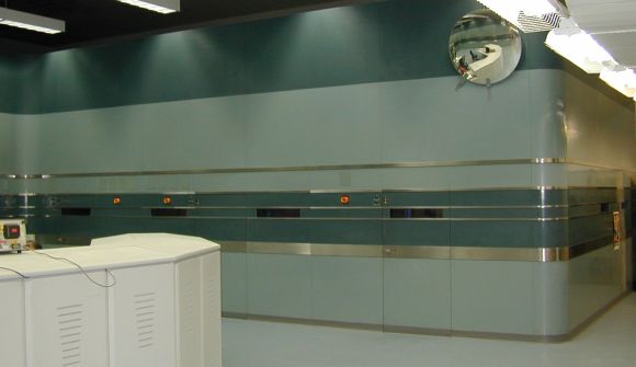
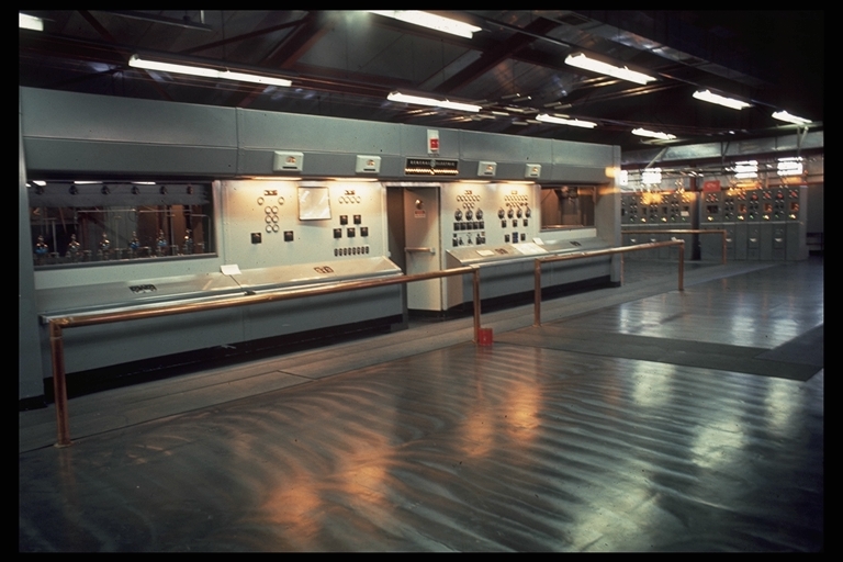
View from inside AN/FRT-4 -
looking out at AN/FRT-18
 |
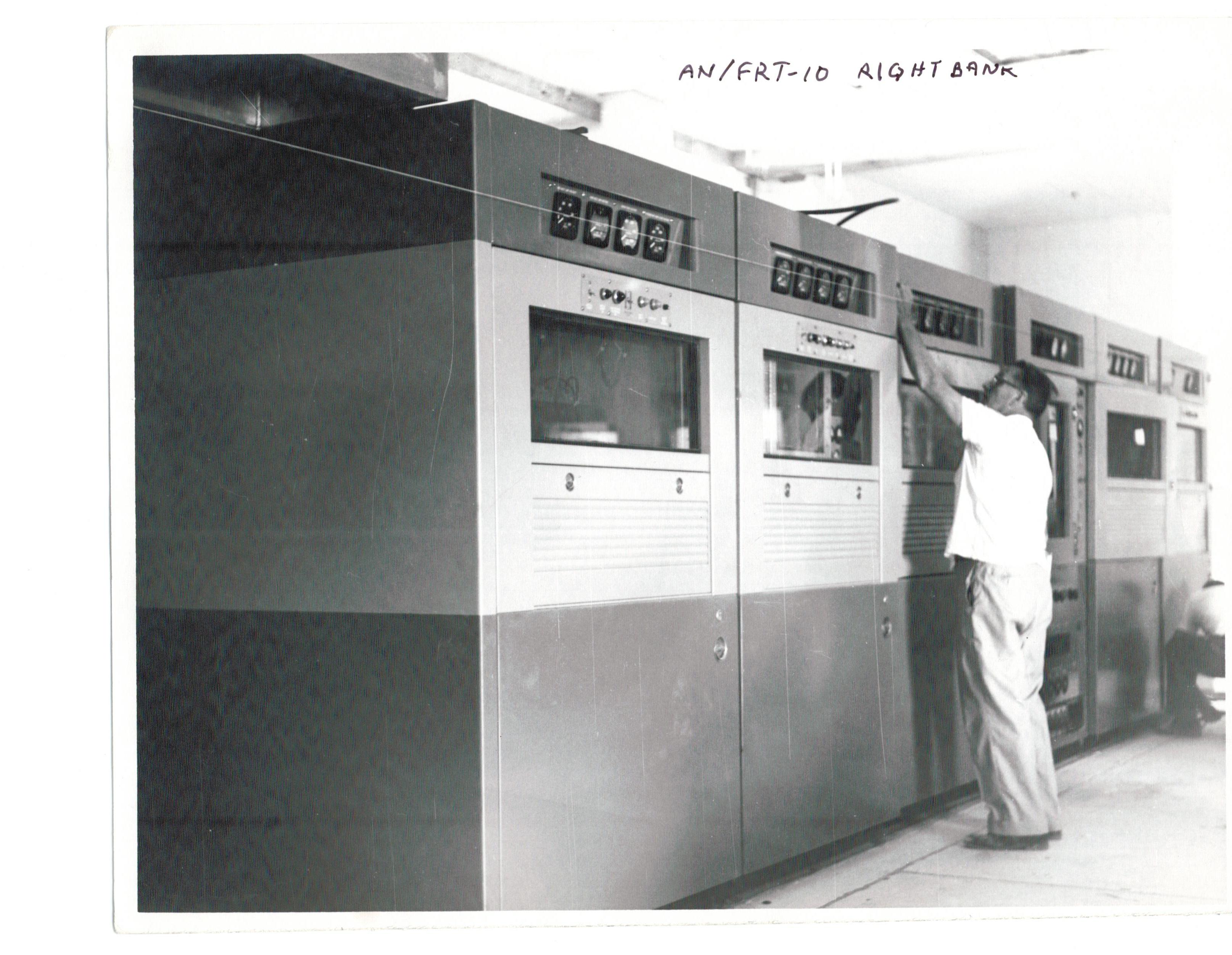
| AN/FRT-10
photos thanks to NF7M
|
500 kw LF 100-200 kc CW/FSK - spec
sheet
dual 250 kw transmitters
diesel engines for p/s
installed at Guardamar, Spain
|
Info from John Cobb:
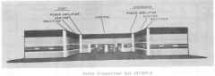
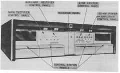
"The AN/FRT-10 was unique, a 500 kW LF giant tuning 100 - 200 kHz. It was in two amplifier bays, which we drove alternately with an external TMC
synthesized exciter stack, running the single-channel KSUB broadcast at about 50 kW. It fed a 1200-foot tower, through 8-inch rigid coax and a big
variometer/capacitor network in the helix house. The amplifier bays each
consisted of IPA and driver stages for the finals: four air-cooled 6697 triodes in grounded-grid push-pull configuration!"
|
FRT-10 right bank
 |
Main building & power plant (6 diesels)
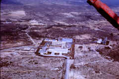 |
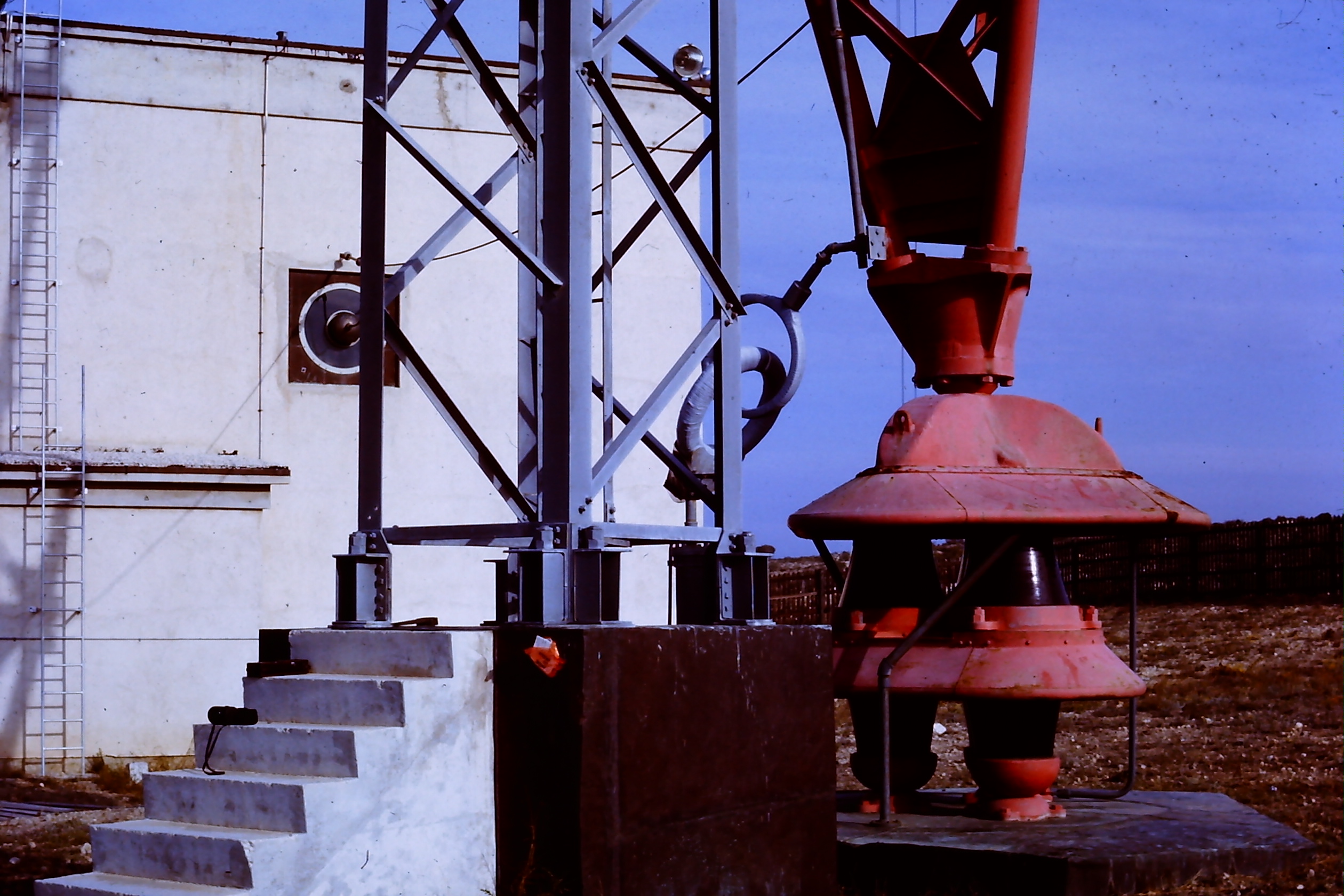
Tower base & helix house
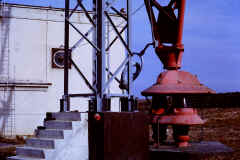
|
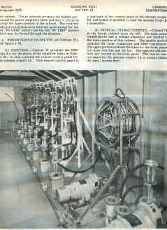
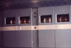
Left side rear view of the PA and front of the circuit breakers panel

|
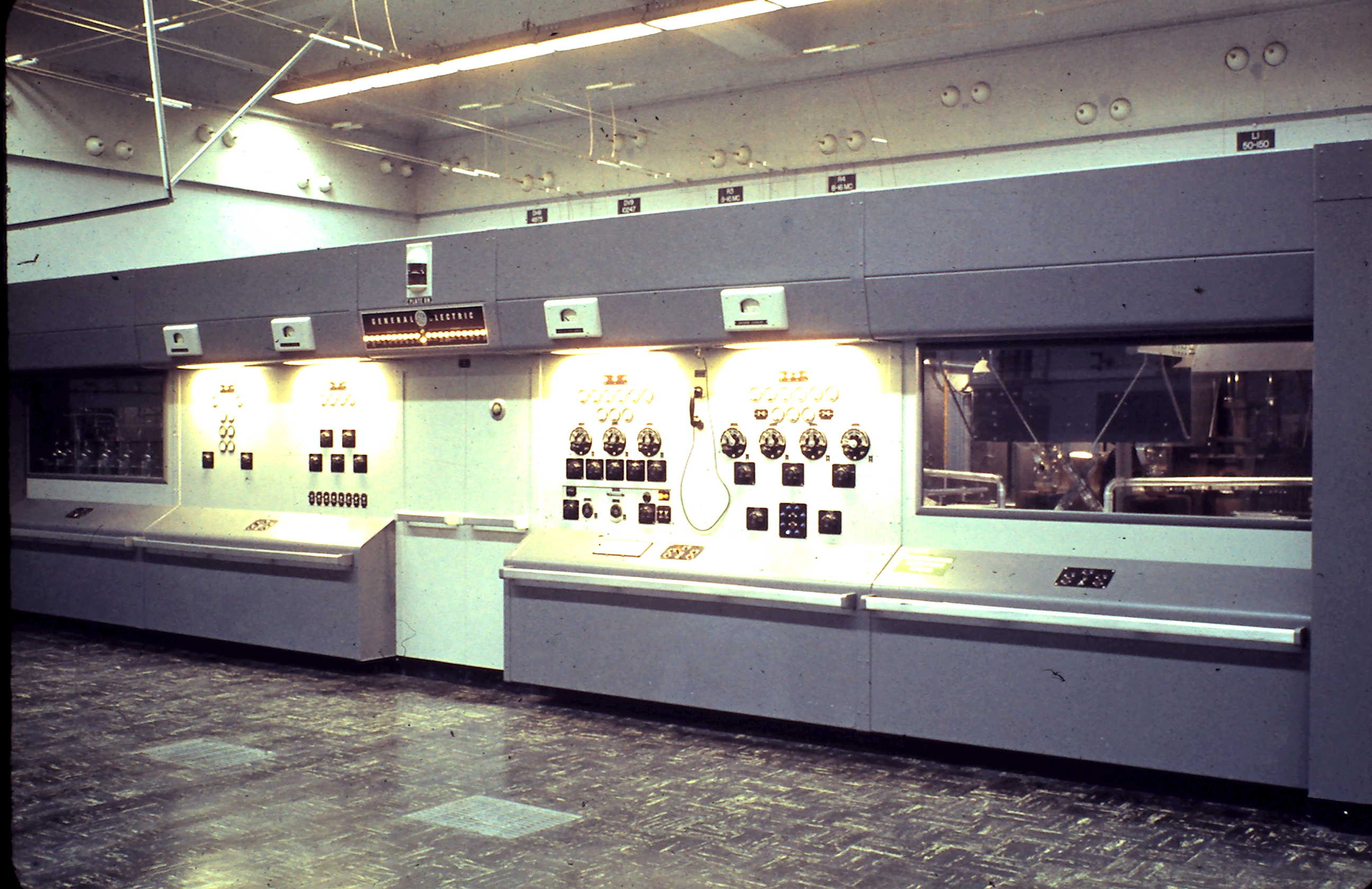
Left - front of one half of the main control
 |
Two exciters driving the AN/FRT-10
 |
Power supplies for the right side PA
|
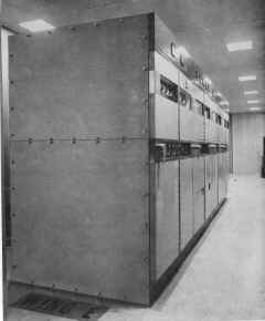
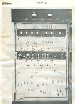
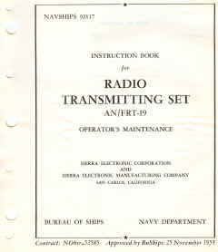
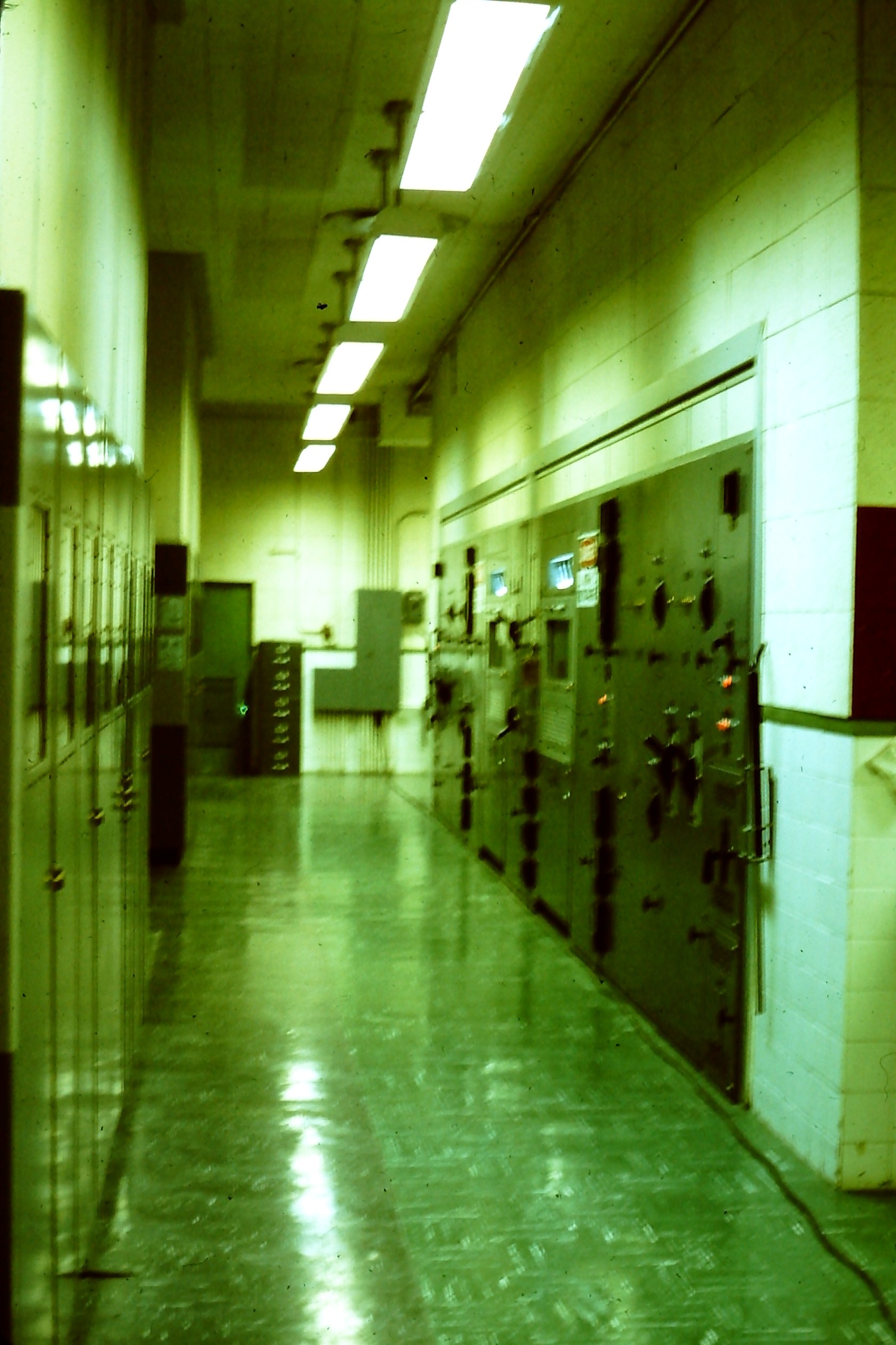
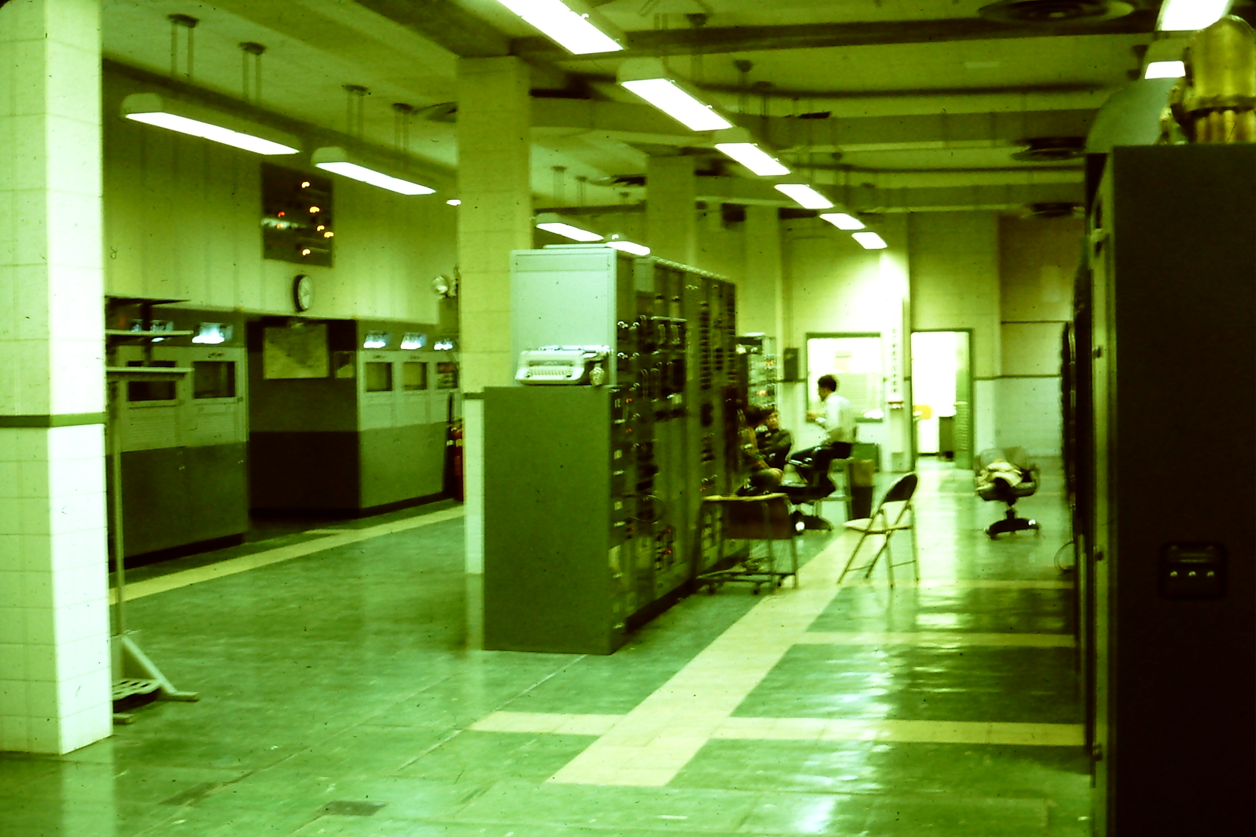
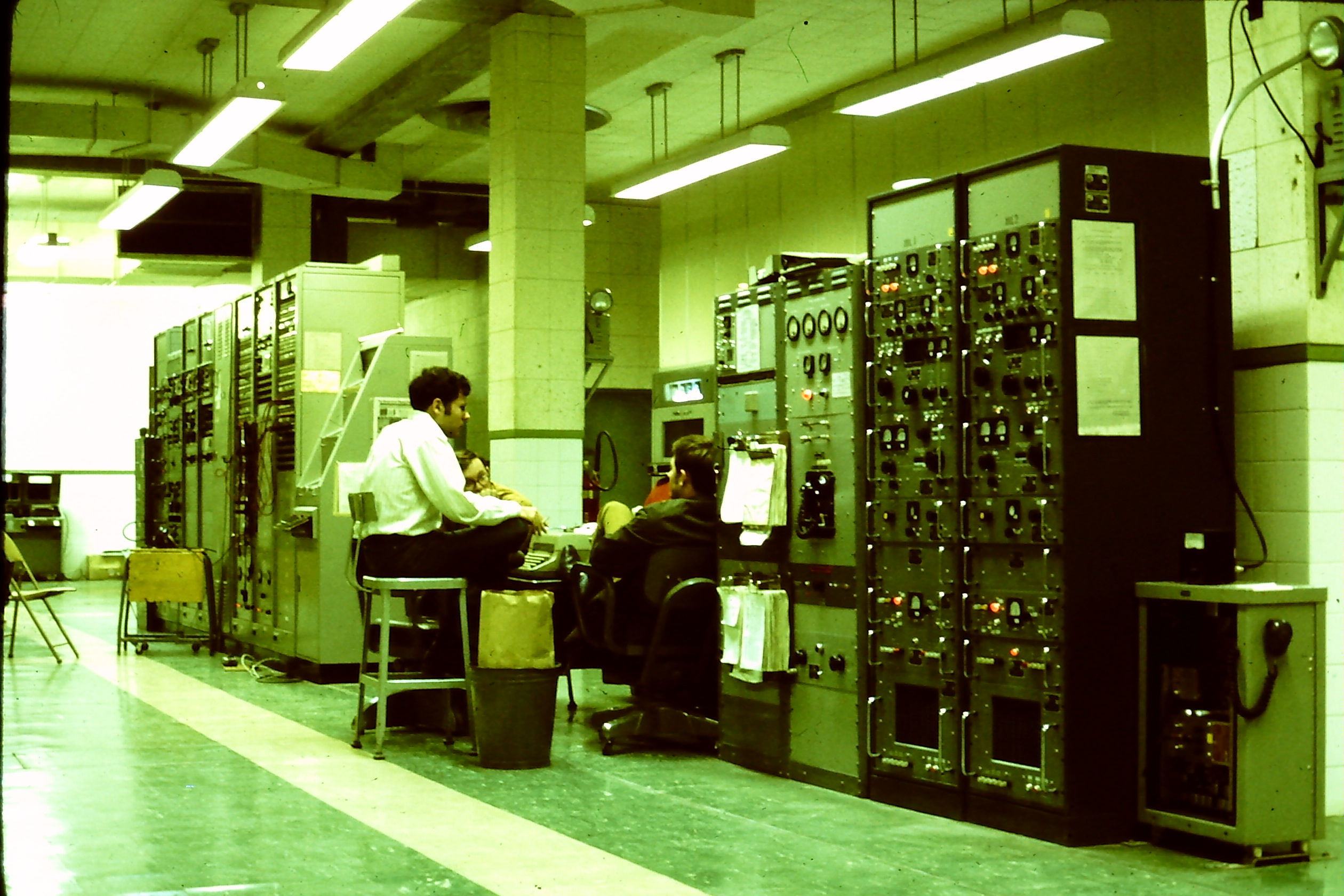
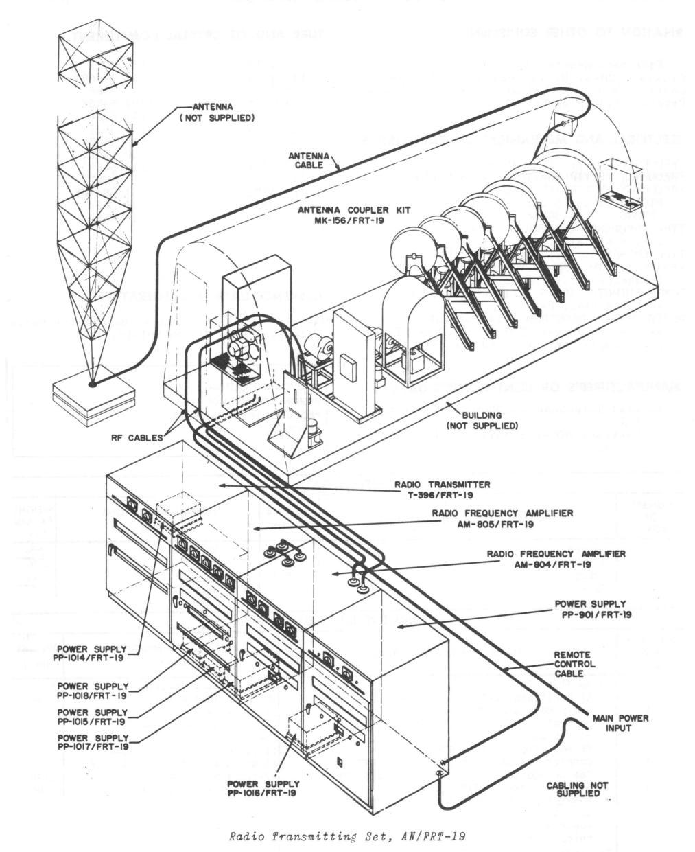
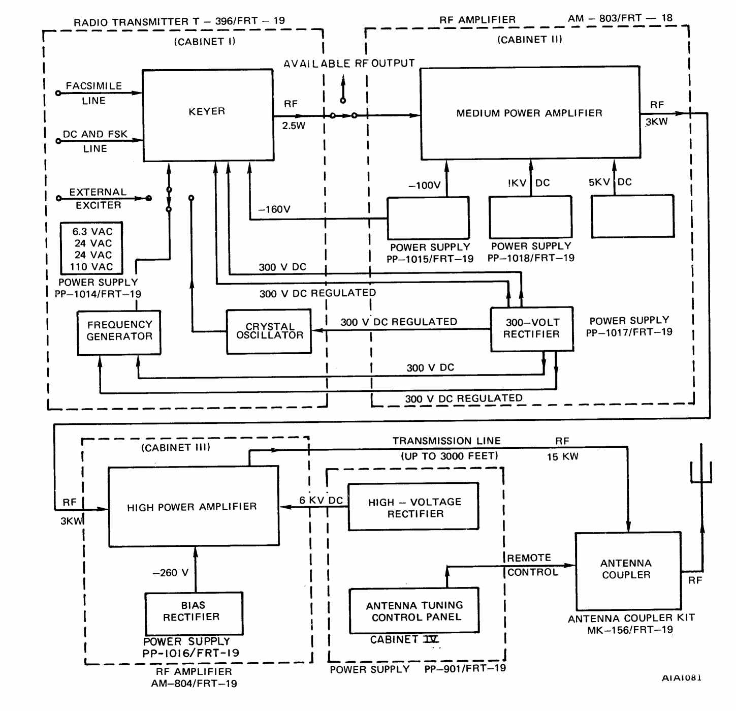
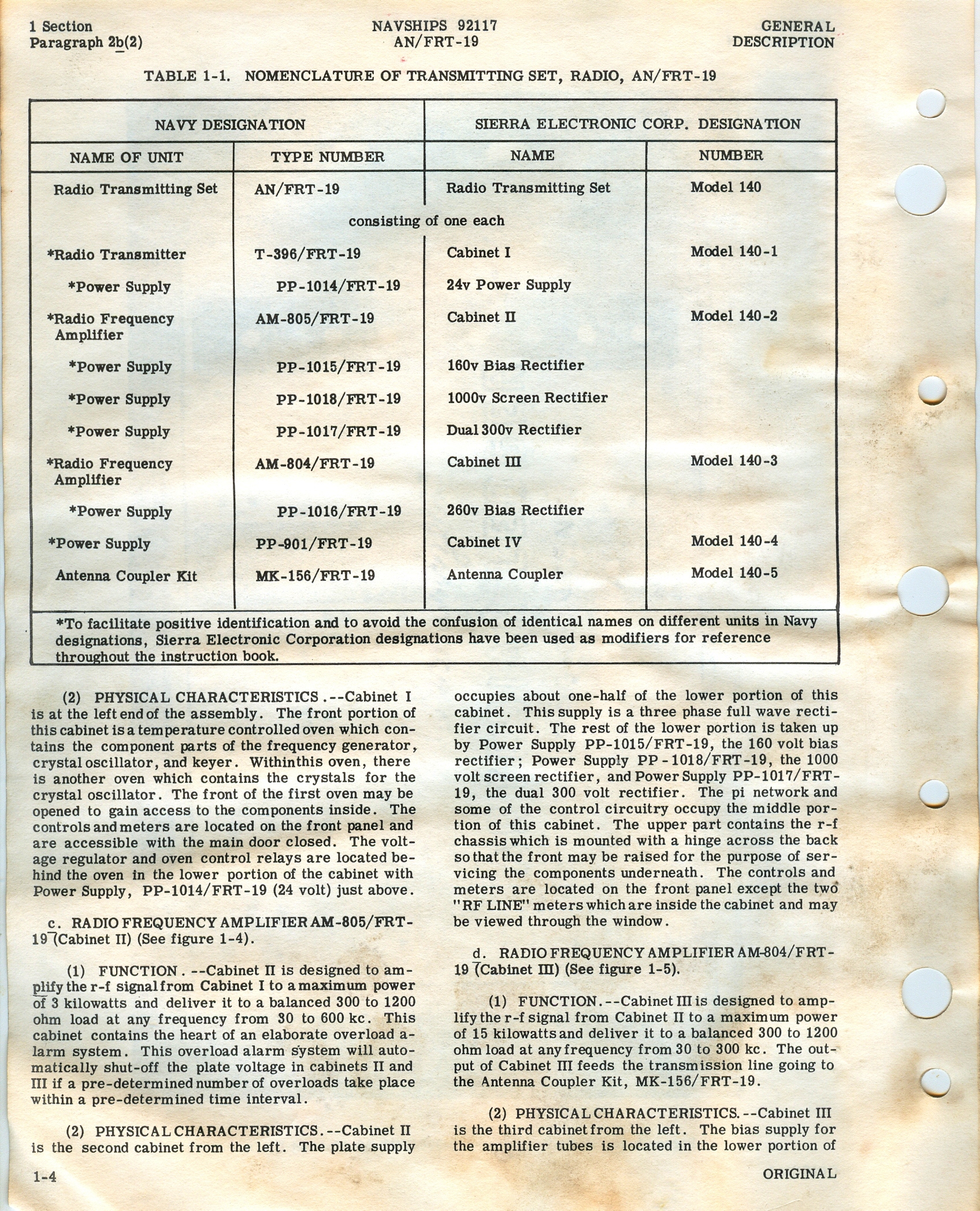
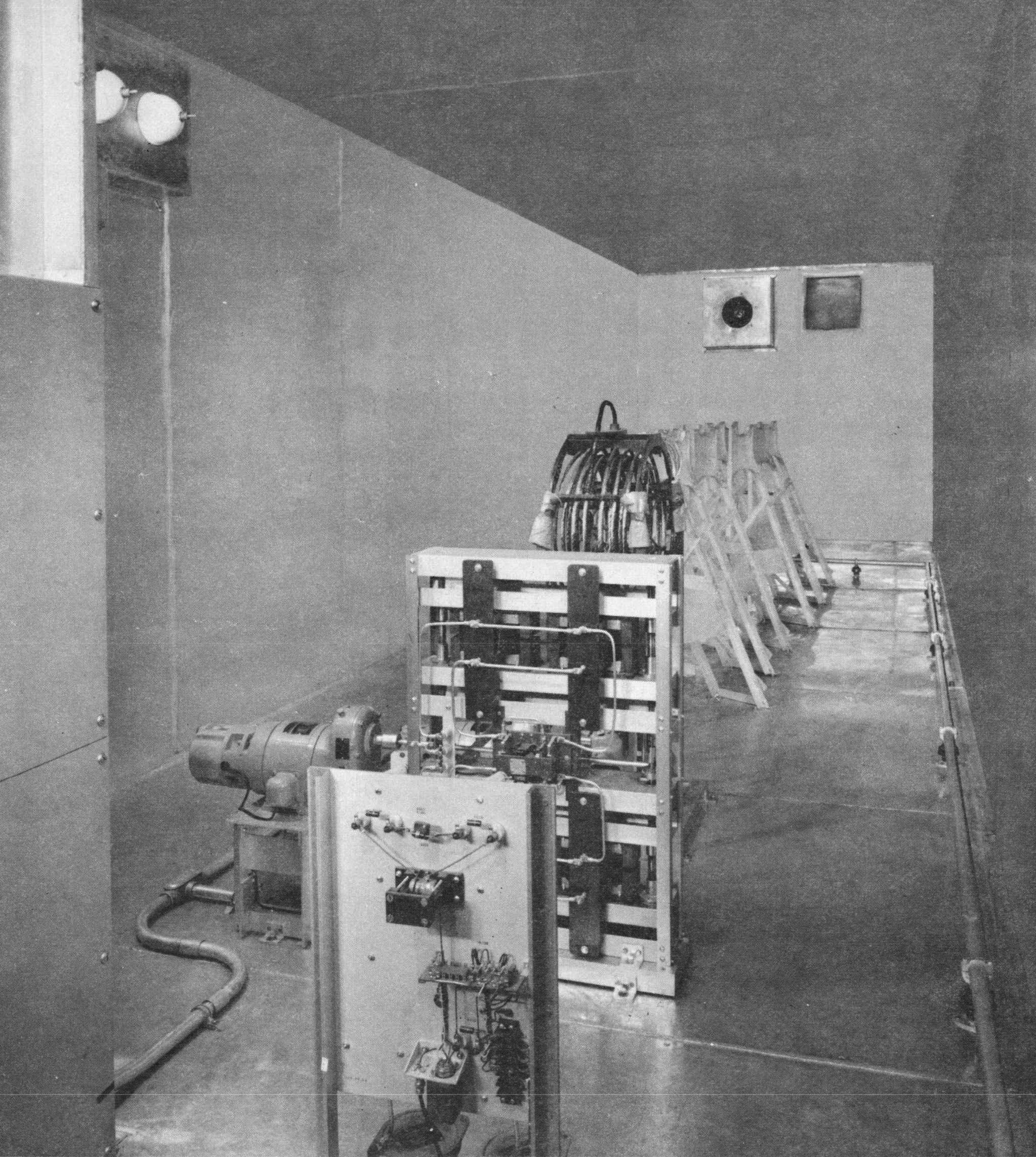
| AN/FRT-19
|
 |
15 kw LF 30-300 kc CW/FSK
3 kw LF 300-600 kc CW/FSK

|
Manual NAVSHIPS 92117
Manuf by Sierra Electronics
Used at NAVCOMMSTA Iceland (Grindavik) and at NAVCOMMSTA Greece (Kato
Souli)
|
|
|
|
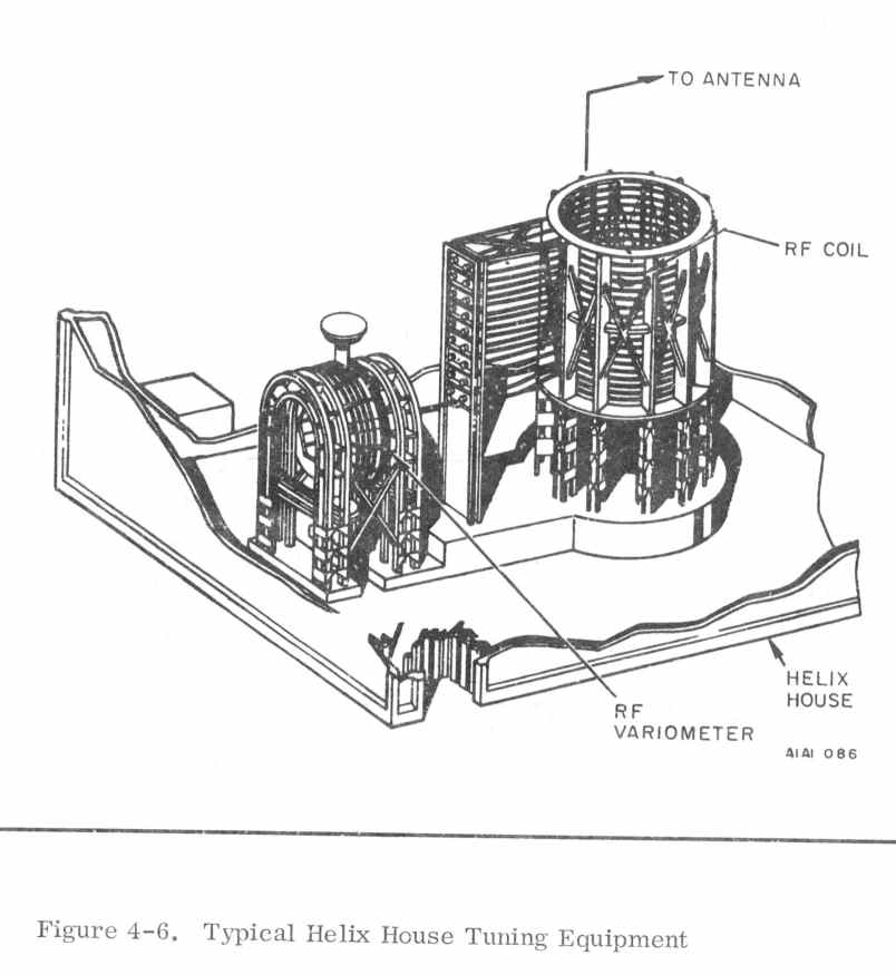
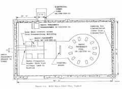
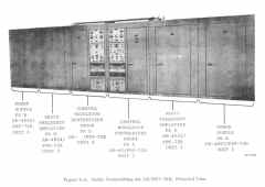
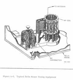
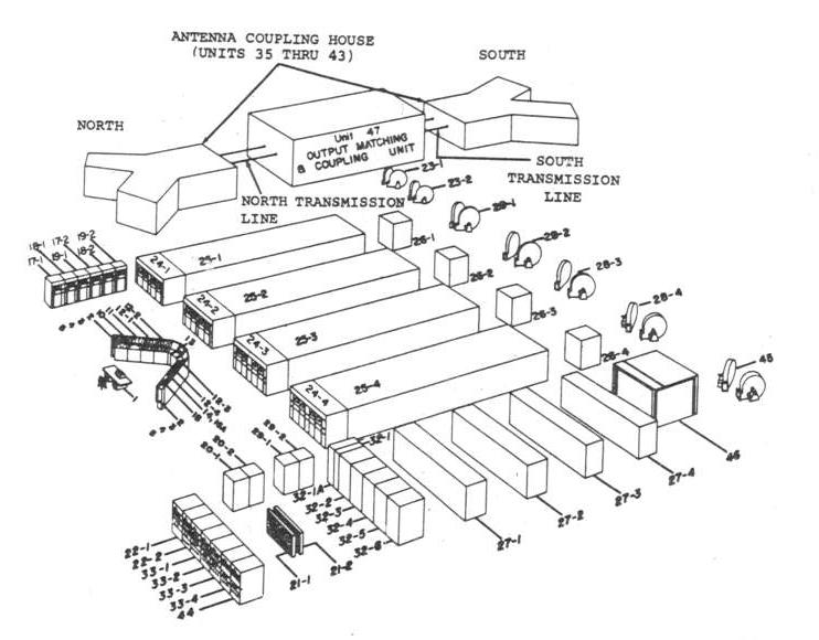
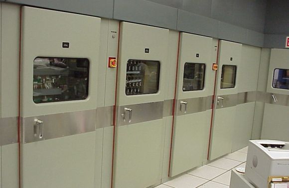
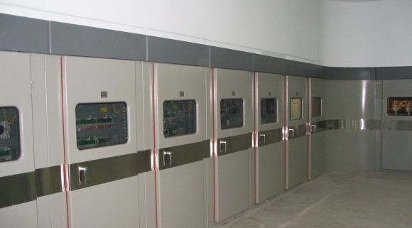
The antenna coupler includes a matching network and its control system, a 48
volt DC power supply, and a regulated 105 volt DC power supply. The antenna coupler matches
the impedances of the transmission line and the antenna tower, for frequency-antenna
height combinations listed in table 4-1. This is done by means of a variometer and a
vari-coupler driven by motors, and several capacitors and inductors which may be
switched into or out of the circuit electrically. Control is afforded by a local control
panel in the house, and remotely by a similar panel in cabinet IV.
|
|
|

|
|
| AN/FRT-31
More Cutler & FRT-31 photos and info

|
2MW VLF (17.8 / 24 kc) -
four separate 500-kw final amplifiers, each with eight ML-6697
air-cooled tubes operating in push-pull parallel
In 2000, the AN/FRT-31, -64 and -67 were upgraded with digital sine wave synthesis solid-state IPA for the tube final PAs
|
installed at NAA Cutler, ME
|
Manual NAVSHIPS 94356
Manuf by Continental Electronics
cost $2,530,814
More Cutler & FRT-31 photos and info
Bill Heidig's great photos
|
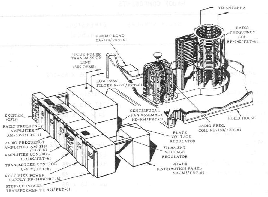
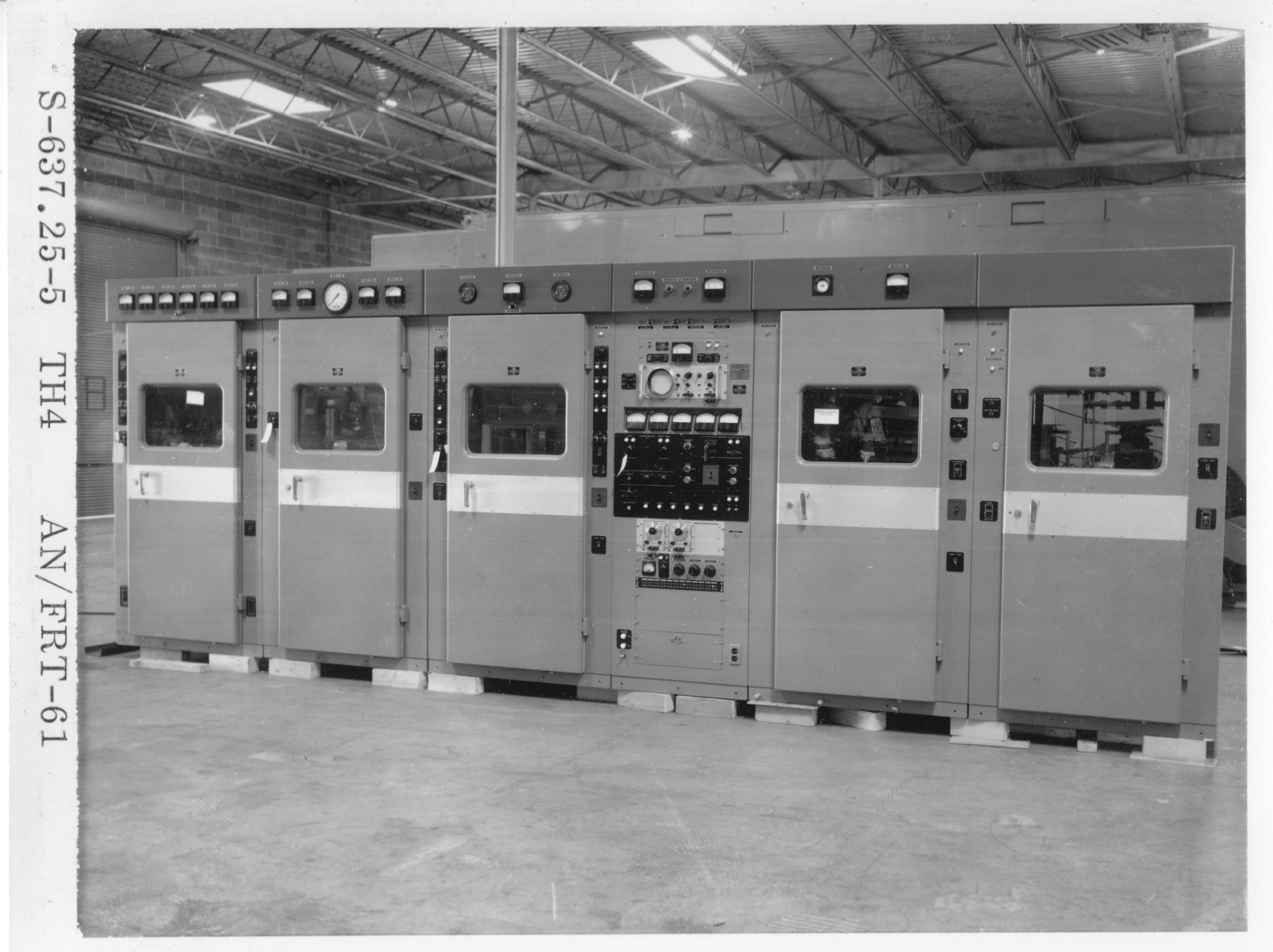
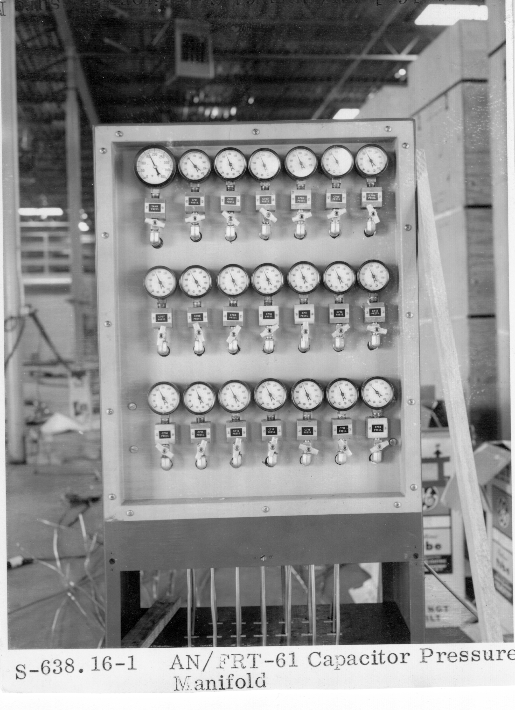
| AN/FRT-61
Manuf by Continental Electronics
cost $299,633.
Used in AN/TSC-35 transportable COMMSTA - and elsewhere?

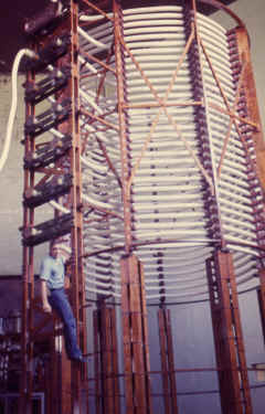
|
AN/FRT-61 Helix House
|
100 kw peak, 50 kw average
50-150 kc CW / FSK
Manual NAVSHIPS 94592
|

|
AN/FRT-64
installed at NPM Lualualei, HI
(replaced TAW-a)
Q: Also at Yosami Japan?
|
1MW VLF (21.4 / 23.4 kc)
FSK +/-25 cycles
|
similar to AN/FRT-31 but with water-cooled finals
In 2000, the AN/FRT-31, -64 and -67 were upgraded with digital sine wave synthesis solid-state IPA for the tube final PAs
Manuf by Continental Electronics
Manuals NAVSHIPS 95884,
0967-LP-384-1010
Lualualei site
photos
Bill Heidig's great photos
|
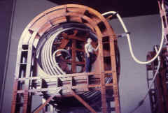
|
Lualualei variometer
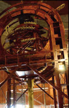
|
-- |
--
|
--
|
| AN/FRT-67
|
AN/FRT-67 Helix Room |
2MW VLF (19.8 / 22.3 kc)
Manuf by Continental Electronics
In 2000, the AN/FRT-31, -64 and -67 were upgraded with digital sine wave synthesis solid-state IPA for the tube final PAs
installed at NWC Harold E. Holt, Exmouth, Australia
More Holt info and photos
|
|
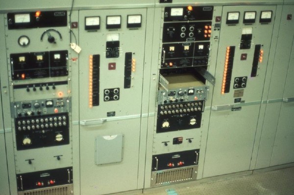
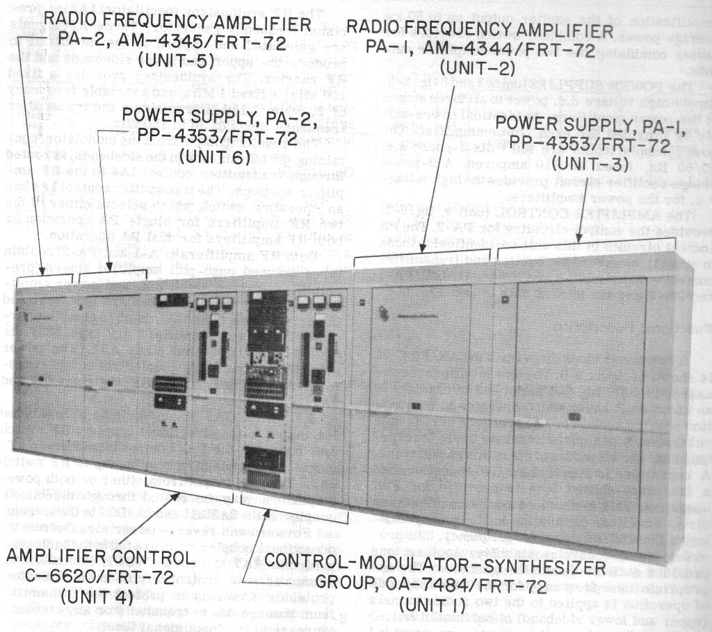
AN/FRT-72
AN/FRT-72A
Bouknadel 1970
(thanks to Darian Paganelli) |

|
100kw peak, 50 kw average
30-150kc
|
NAVSHIPS 0967-033-8000
manuf by Continental Electronics
Note - FRT-72's from Driver,
Grindavik, and Thurso were moved to
Colorado for use at WWVB
- photo here
Thurso helix house today - photo
|
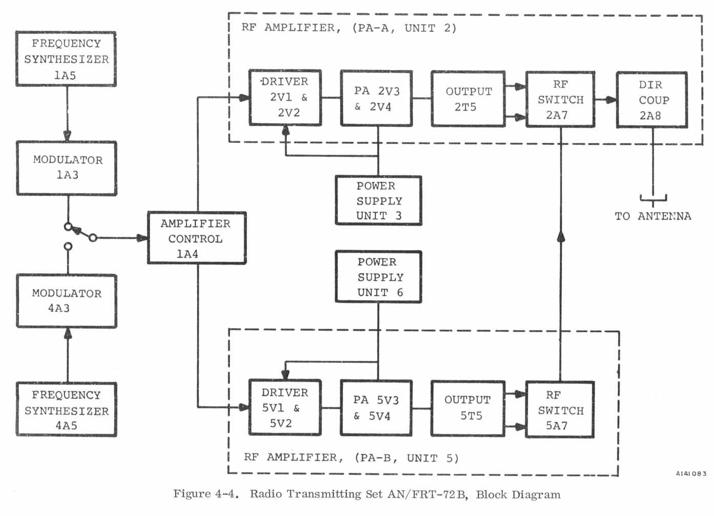
AN/FRT-72B
Bouknadel 1970
(thanks to Darian Paganelli) |
|
100kw peak, 50 kw average
30-150kc
|
manuf by Continental Electronics
|
AN/FRT-73
|
installed at NBA Summit, Panama
|
Manuf by Continental Electronics
|
|
1 MW VLF water-cooled
|
|
|
| AN/FRT-74
need photo & info
|
10 kw
5-550 kc
TMC GPT-10KLF
|

|
| AN/FRT-87
|
1 MW VLF
Manuf by Continental Electronics
Click
Here for photos and info
|
installed at NSS Annapolis, MD
Bill Heidig's great photos
|
|
| Info from Roy K1LKY "I was fortunate to visit the VLF station at NSS Annapolis before it was dismantled. On that trip we learned that the narrow shift FSK keying put the carrier alternately on either side of the center of the tuned system. It was some 10 percent down the slope (memory of the details are faint.) But the antenna current was monitored at the console and would vary depending on how far down the slope the tuning had shifted the center of the very narrow sweet spot. The operator could vary one of the inductors in the system by remote control to match the two currents. That system operated at 20.4 kc I believe, at an output power of about eight tenths of a megawatt. The shift may have been on the order of 10 to 15 CPS. The antenna was one mile long, about 800 to 1200 feet up, and was tuned with a massive inductor made of five inch diameter
Litz wire. Cutler Maine still operates with similar parameters, as far as I know."
|
| AN/FRT-95 |
need photo |
modern 250kw solid-state LF (40kHz)
installed at Aguada, PR, Niscemi IT, Keflavik, and Awase
|
| AN/FRT-95 at NDK LaMoure, North Dakota |
"The VLF transmitter is a prototype solid state amplifier developed under the Solid State Power Amplifier Replacement
(SSPAR) program" |
| AN/URT-30 |
Shore Station VERDIN transmitter |
CLARINET PILGRIM communicated to submarines piggybacked on USCG LORAN
transmissions
|
|
|
|
|


