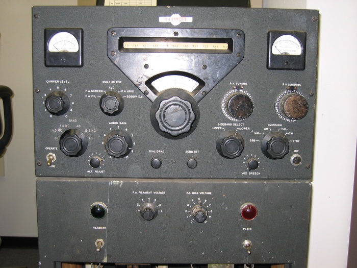
AN/BRT-2
Circuit Mayflower
![]()
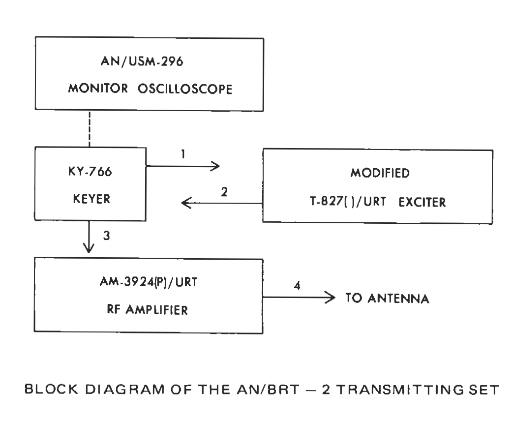
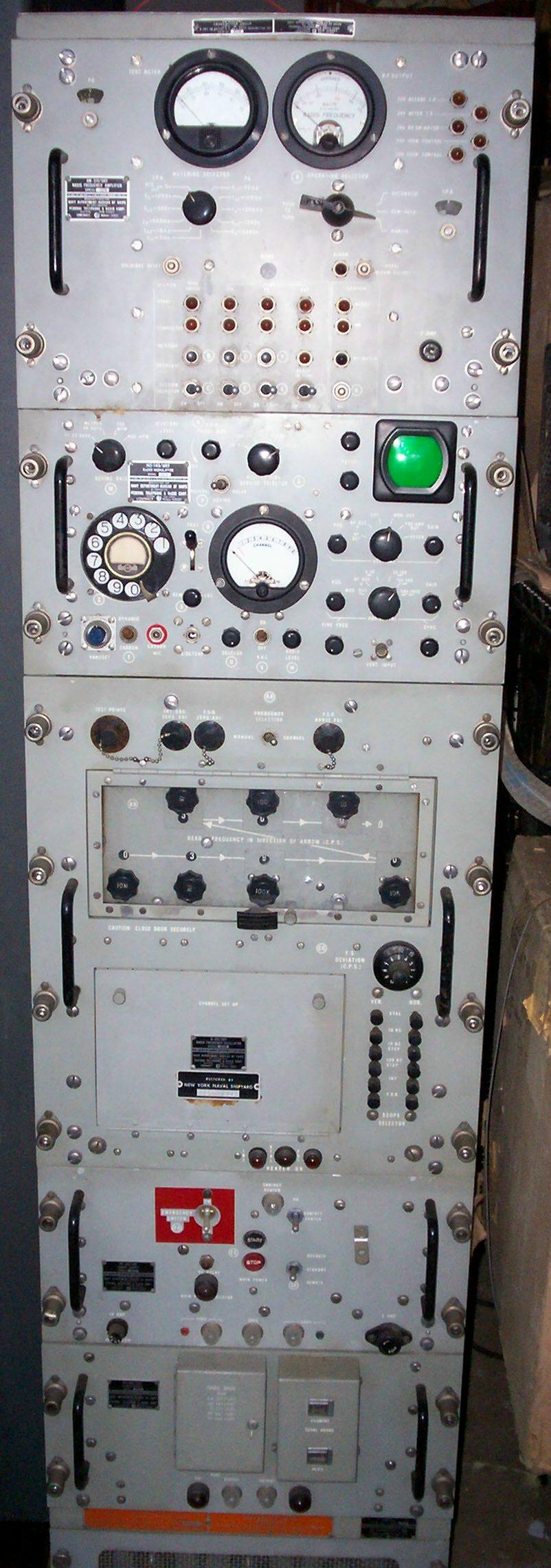
1995 Submarine Communications Plan - "The Circuit Mayflower (Shipboard) System is installed on a variety of U.S. Navy ships to provide a one-way-ship-to-shore HF radio link. It consists of an AN/BRT-2 system which has a KY-766A Keyer, TS-3858 silent tuner, modified AN/URT-23, AN/UGC-136CX teleprinter, and AN/USM-488 oscilloscope. The teleprinter is used to control the Keyer and to input various strings of coded messages from a classified codebook. The modification of the existing KY-766/BRT-2 Keyer to the KY-766A/BRT-2 configuration, which began in September 1991, will be completed in FY96. This change modified the existing punched tape reader and associated electronics of the KY-766/BRT-2 and replaced it with a direct electrical interface from the AN/UGC-136CX teleprinter via the SA-2626/BR and black switch board."
"The Submarine shore HF infrastructure is operated and maintained by the Commander, NCTC and consists of eight HF receiver sites and eight HF transmitter sites. The HF receiver sites support the submarine Circuit Mayflower and Clarinet Merlin systems while the HF transmitter sites rekey the Strategic SSBN submarine broadcast. Functional control of the Clarinet Merlin and Circuit Mayflower programs are in process of being transferred to the Submarine TYCOMs. COMSUBLANT/COMSUBPAC will assume the lead responsibility for operation of the Circuit Mayflower and Clarinet Merlin Systems in their respective AORs. Naval Computer and Telecommunications Area Master Station, Atlantic (NCTAMS Lant) will maintain responsibility for maintenance of the Circuit Mayflower System worldwide. This transfer will start mid FY96 and be completed during FY97."
?? Possibly related to use of AN/WRA-3 and AN/WRT-4 ??
AN/BST-2
CLARINET MERLIN
The submarine emergency
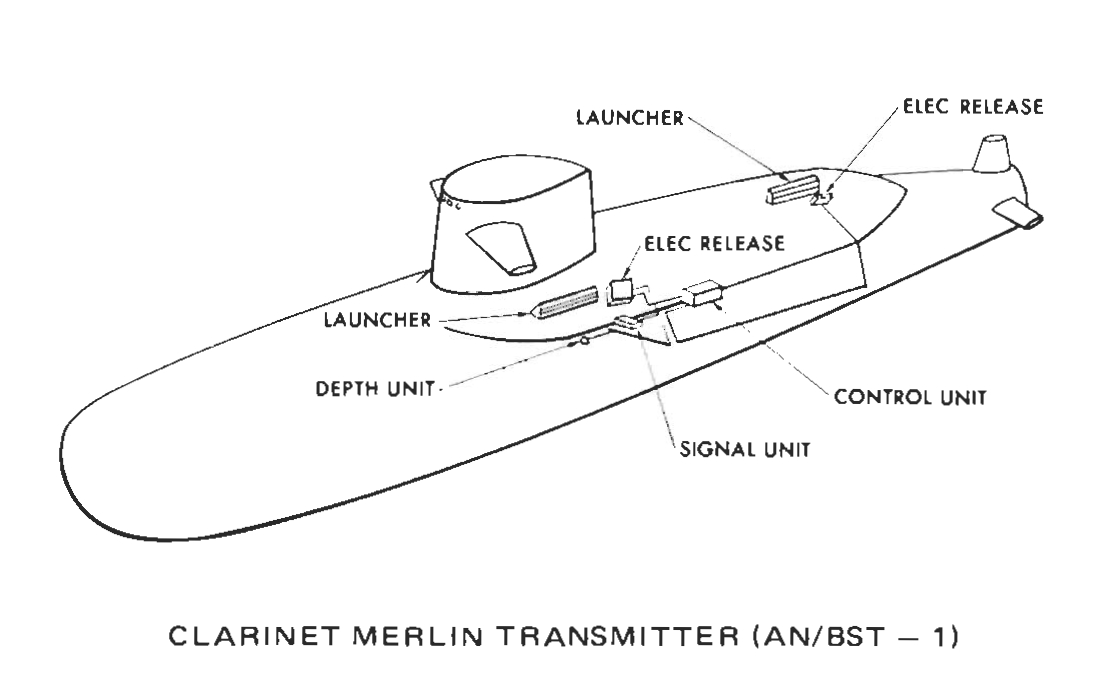
communication transmitter (CLARINET MERLIN) buoy, if released, should transmit a coded message at 13 to 15 words per minute. The message should consist of the CW characters “HM,” repeated 10 times, “USS OSC,” and three word groups of three characters each. The transmission is about 3 minutes long on each of four frequencies: 6721.5 kHz, 9033.5 kHz, 11264.5 kHz, and 15055.5 kHz.1975 NAVELEX
Brochure - "CLARINET MERLIN is an emergency submarine communications
system. Transmitter buoys, which are part of the AN/BST-1 transmitting subsystem, are automatically launched
from the submarine when an "in extremis" environment is sensed, and transmit a pre-selected message. Recieving subsystems,
AN/FRR-87's located at Naval Communications Stations, automatically detect and record the keyed CW
signals.
Upon detection of a signal the AN/FRR-87 shore subsystem automatically alerts operating personnel, who then
copy the message by means of an audio output. The operator can play back the automatically received message recorded on
a cassette tape recorder. Two AN/FRR-87's are maintained "on-line" at each shore site , with two of the four fixed
emergency frequencies coupled through to each of them. A third AN/FRR-87 is provided as a "hot spare", to be available
for immediate substitution in case of failure of either of the on-line receivers."
AN/FRT-39
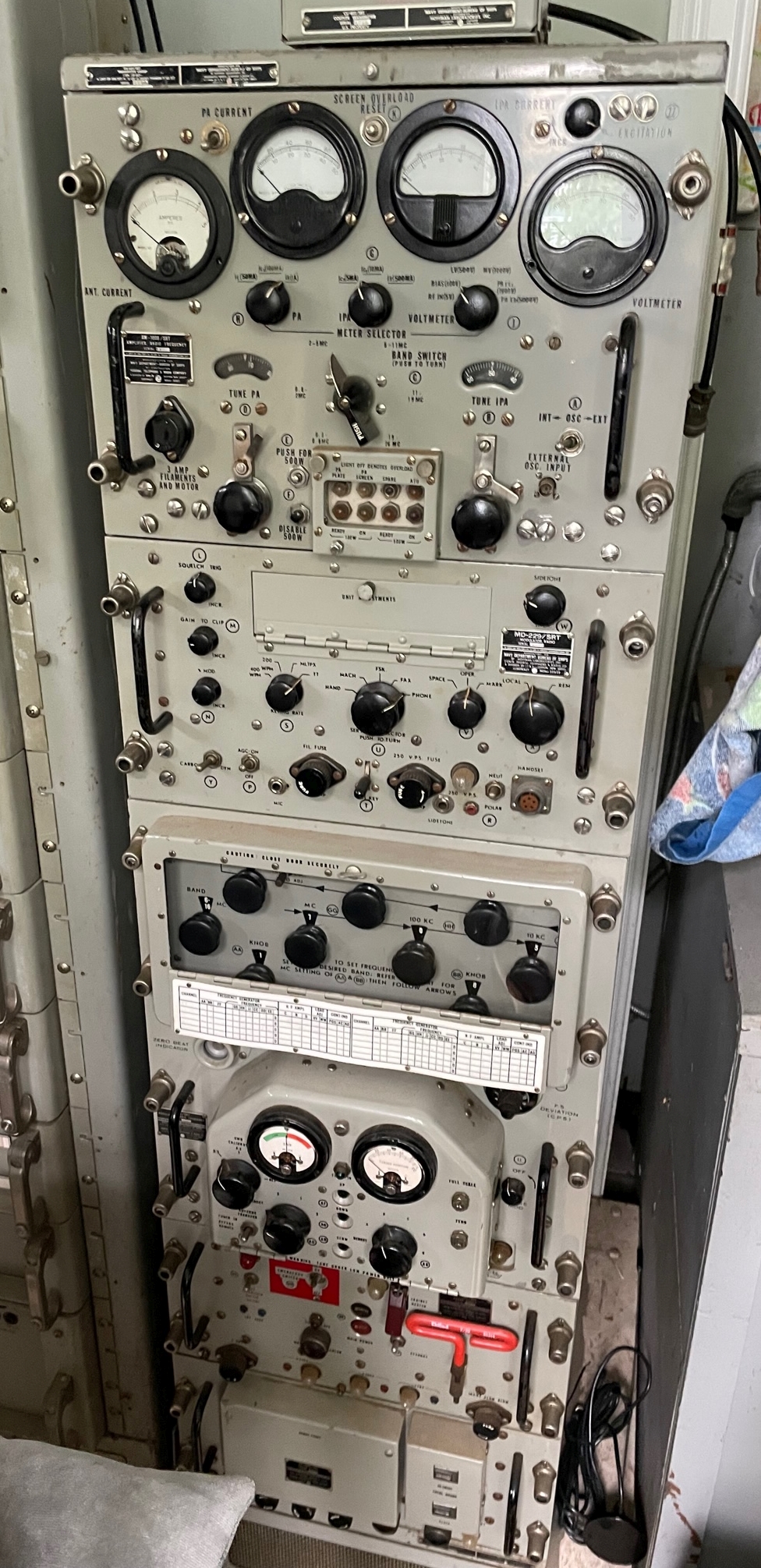
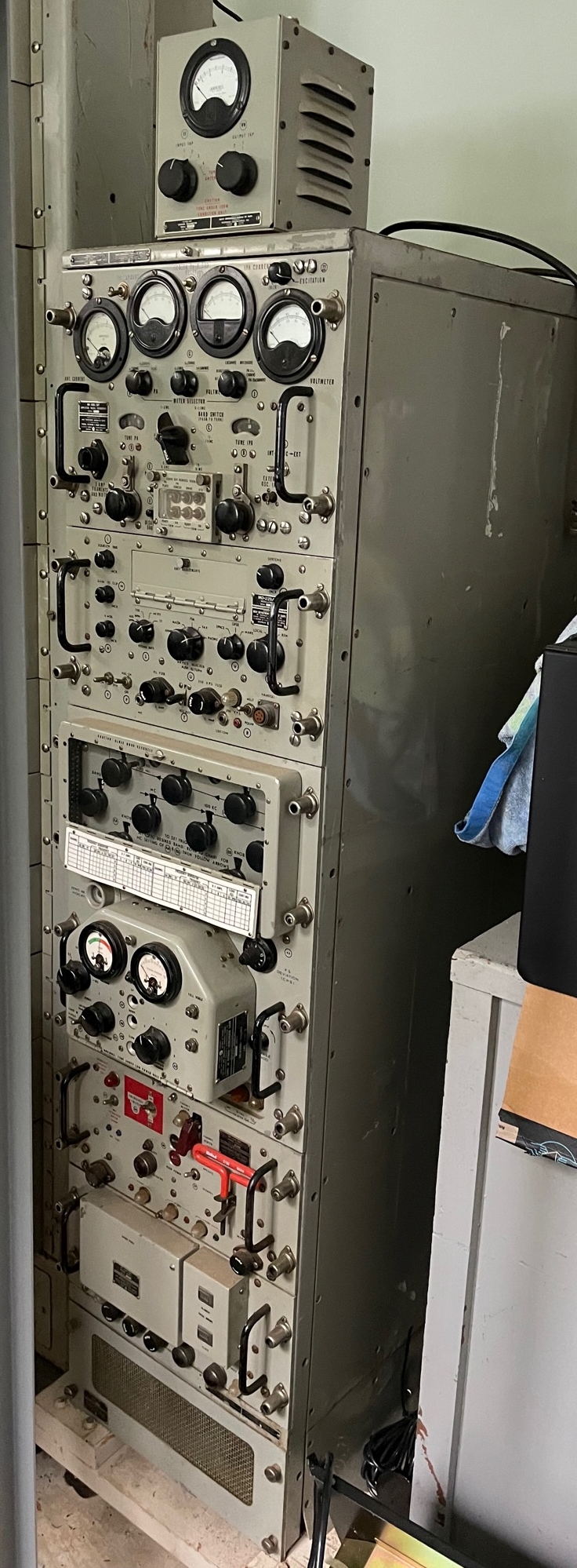
AN/SRT-14
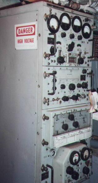
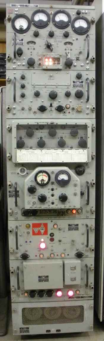
300kc-26mc
synthesized VFO
4-400 final AM/CW/FSK
manuf by Federal
similar to AN/URT-2
includes -
TN-229/SRT antenna tuner
CU-372/SRT antenna coupler
CU-402/SRT load adjusting unit
KN4R's SRT-14
Download Manual
article in Electric Radio magazine April 1997 p4
KN4R's SRT-14
AN/SRT-15
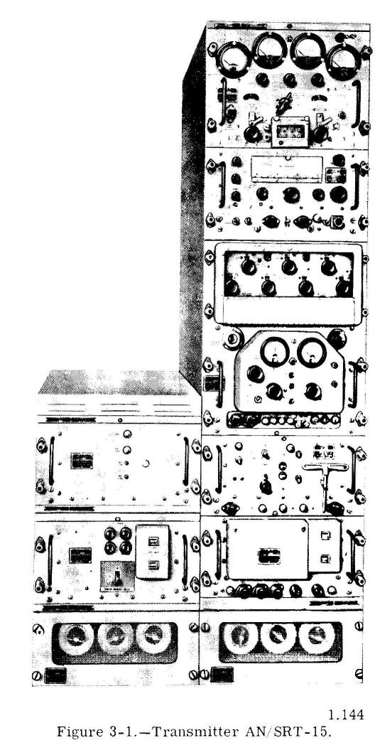
100w 300kc-2mc
500w 2mc-26mc
synthesized VFO
4-400 final AM/CW/FSK
manuf by Federal
similar to AN/URT-3
SRT-14 plus "booster"
(high-power modulator and 3000v power supply)
Download Manual
SSB adaptor manual
NAVSHIPS 92942
(0967-905-4010)
manual
- thanks to AE6SD
AN/SRT-16
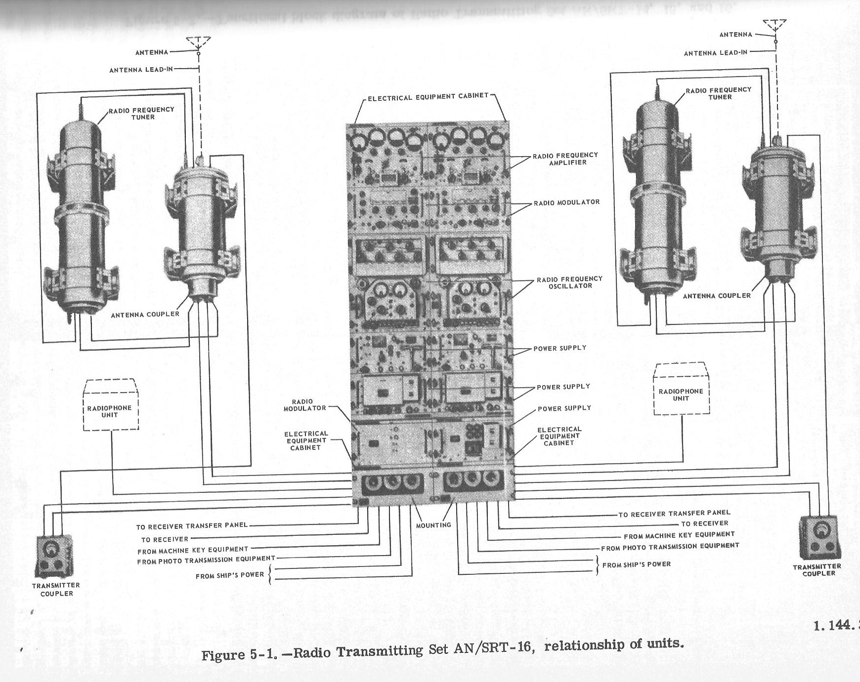
LF/HF dual xmtr
100w 300kc-2mc
500w 2mc-26mc
synthesized VFO
4-400 final AM/CW/FSK
manuf by Federal
similar to AN/URT-4
Download Manual
AN/SRT-17(XN-1)
RCA prototype 1957
Appears identical to USCG's AN/URT-12
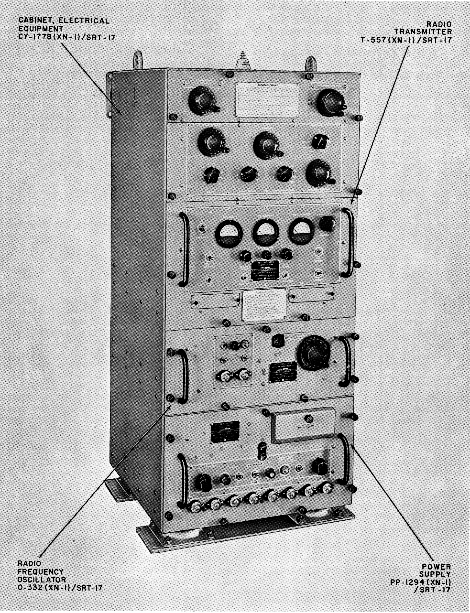
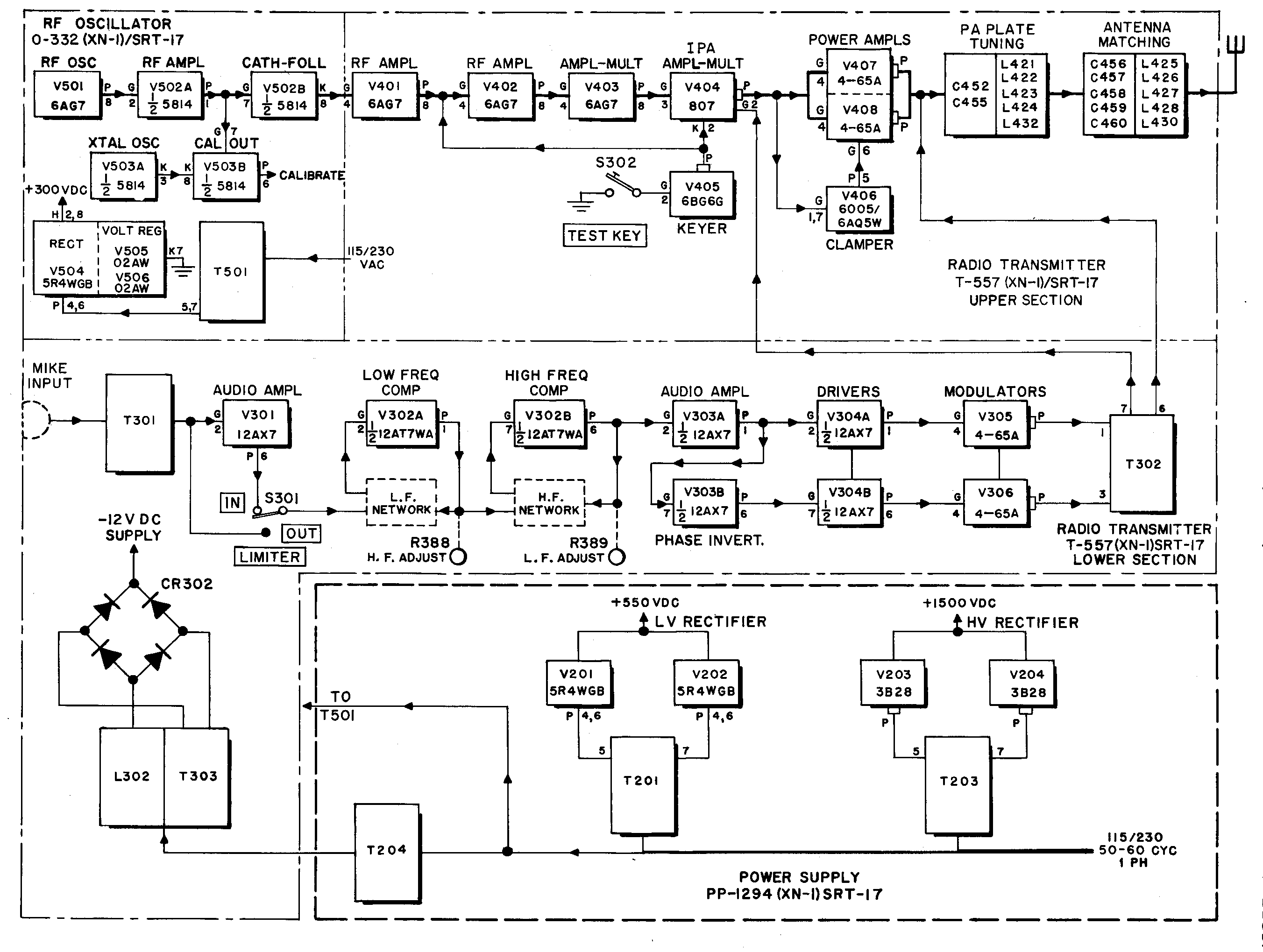
Pair of 4-65 modulated by pair of 4-65
AN/SRT-20(XN-1)
AM-1976(XN-1)/SRT
Amplifier design modified by Advanced Technology Corp 1960
AN/URT-2
AN/URT-3
AN/URT-4
Photos - Accessory Units
100w 300kc-26mc
(URT-3, -4 also 500w 2mc-26mc)
4-400 final AM/CW/FSK
10 channel remote select
(preset frequencies + automatic tuning)
Essentially an auto-tune version of SRT-14, 15, 16 - design predates SRT-14 series
OA-353 Transmitter assembly
C-916/URT remote control
Auto antenna tuner
OA-297/URT controller group +
CB-5/URT capacitor tuning unit +
TN-197/URT inductor tuning unit
Optional "booster" OA-354/URT
(3kv p/s + pair 4-125 modulator)
URT-2 is 100 watts
URT-3 is 500 watts with booster
URT-4 is two URT-2 + booster
NAVSHIPS 92877?
design &
manuf by Federal - see
"An automatic tuning communication transmitter" -
Dettman, M.
IRE International Convention Record
Volume 1, Issue , Mar 1953 Page(s): 137 - 144
An essentially identical article is here
beginning on page 271. An additional article on the automatic tuning
system begins on page 279
AN/URT-12
T-408/URT-12
Coast Guard only?
Same as AN/SRT-17
photos thanks to Sam KF4TXQ
pair 4-65's modulated by 4-65's
manuf by Radiomarine
Transmitter
Mainly shore use - some used shipboard
750 w SSB/AM/CW
includes
AM-1703/URT-17 amp (TMC RTF)
AN/URA-23A exciter (TMC SBE-2)
PP-1768/URT-17 p/s (TMC RTP)
manuf TMC GPT-750-D (URT-17)
GPT-750-D2 (URT-17A)
manual & spec sheets thanks to K4OZY


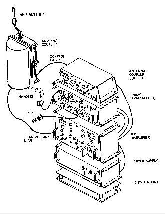
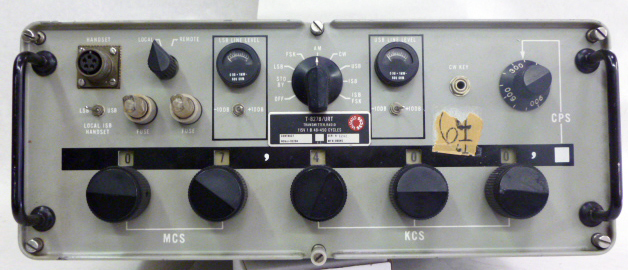
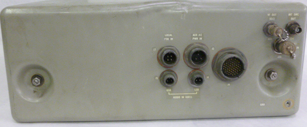
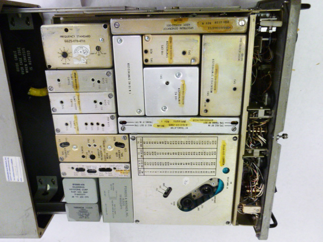
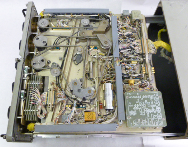
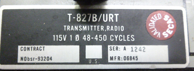
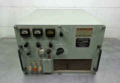
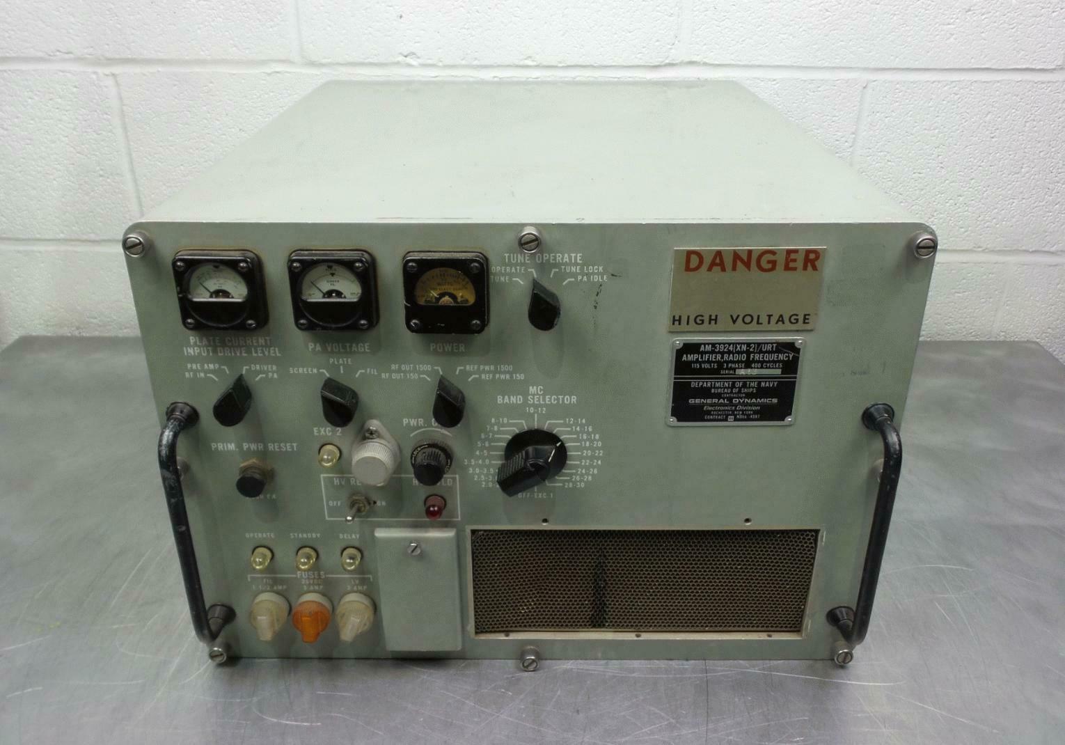
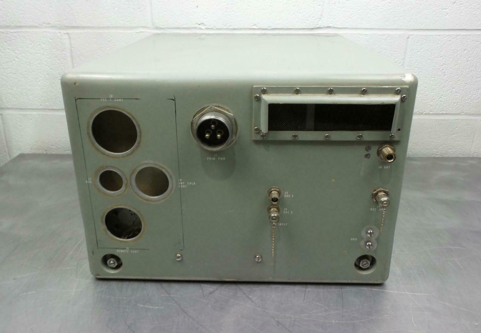
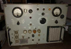
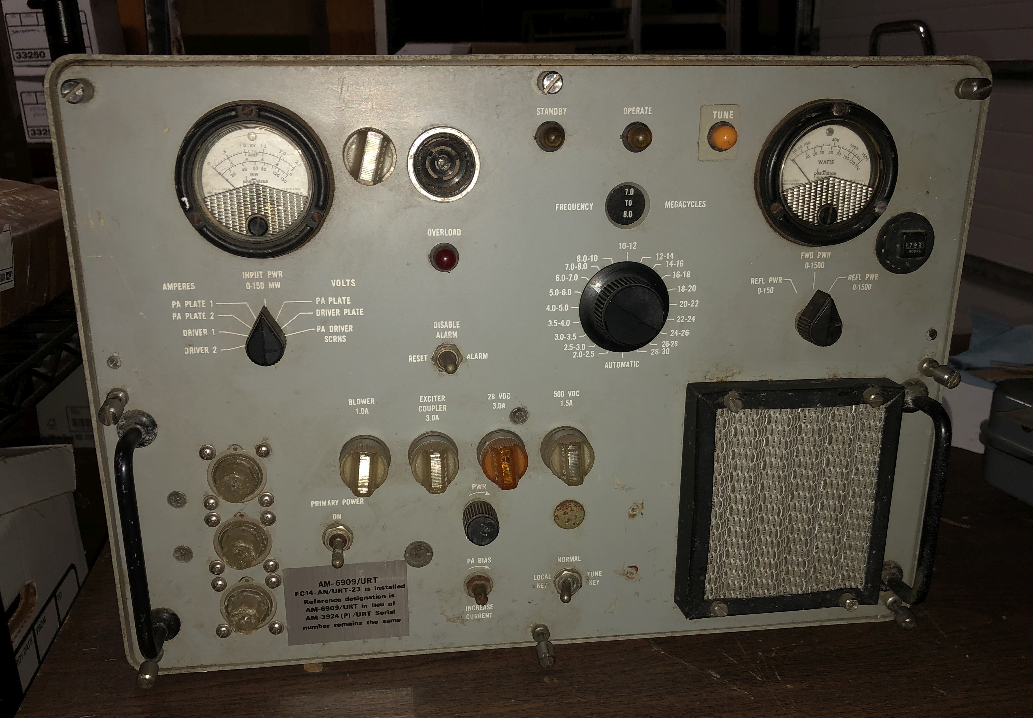
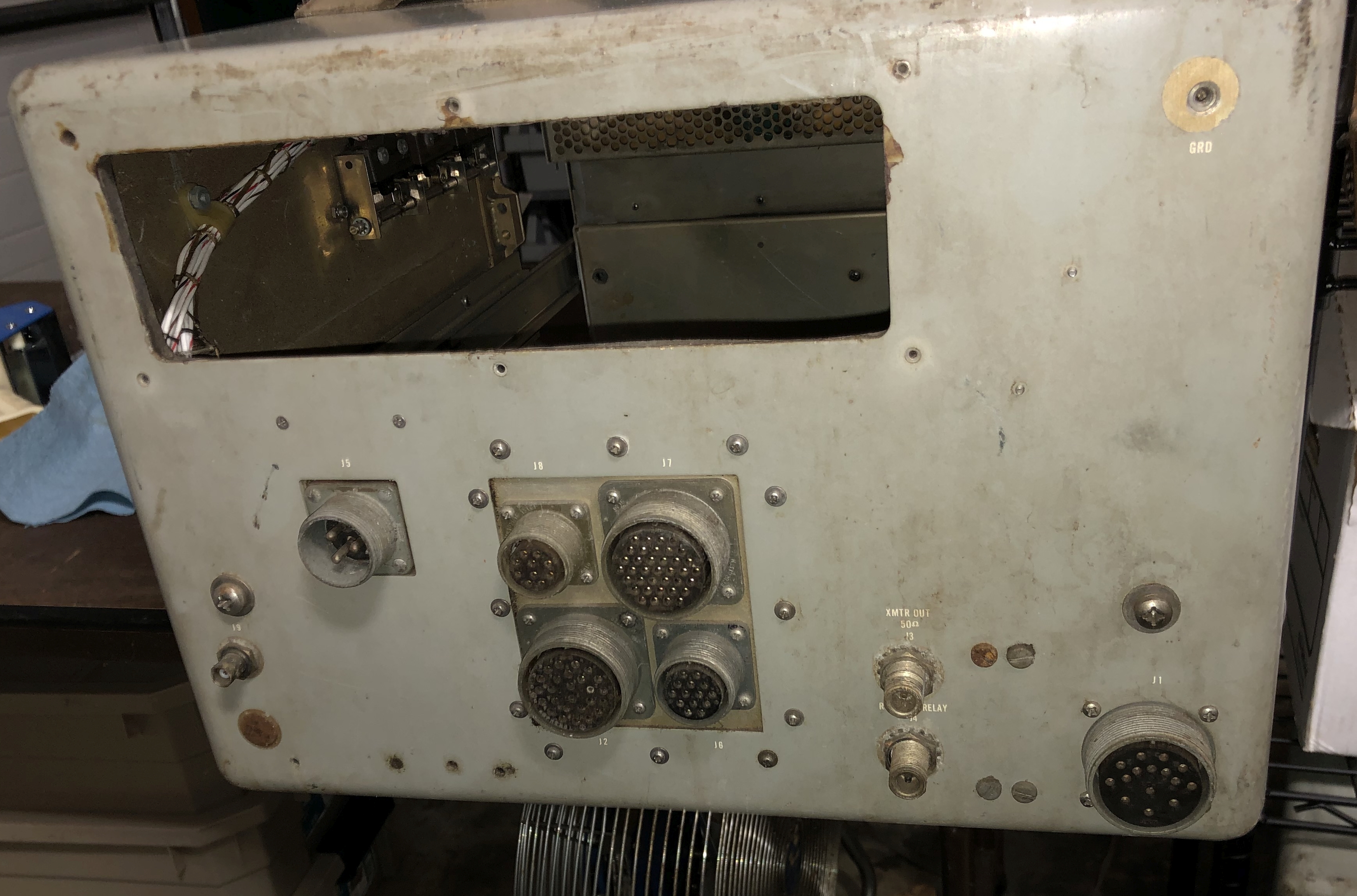
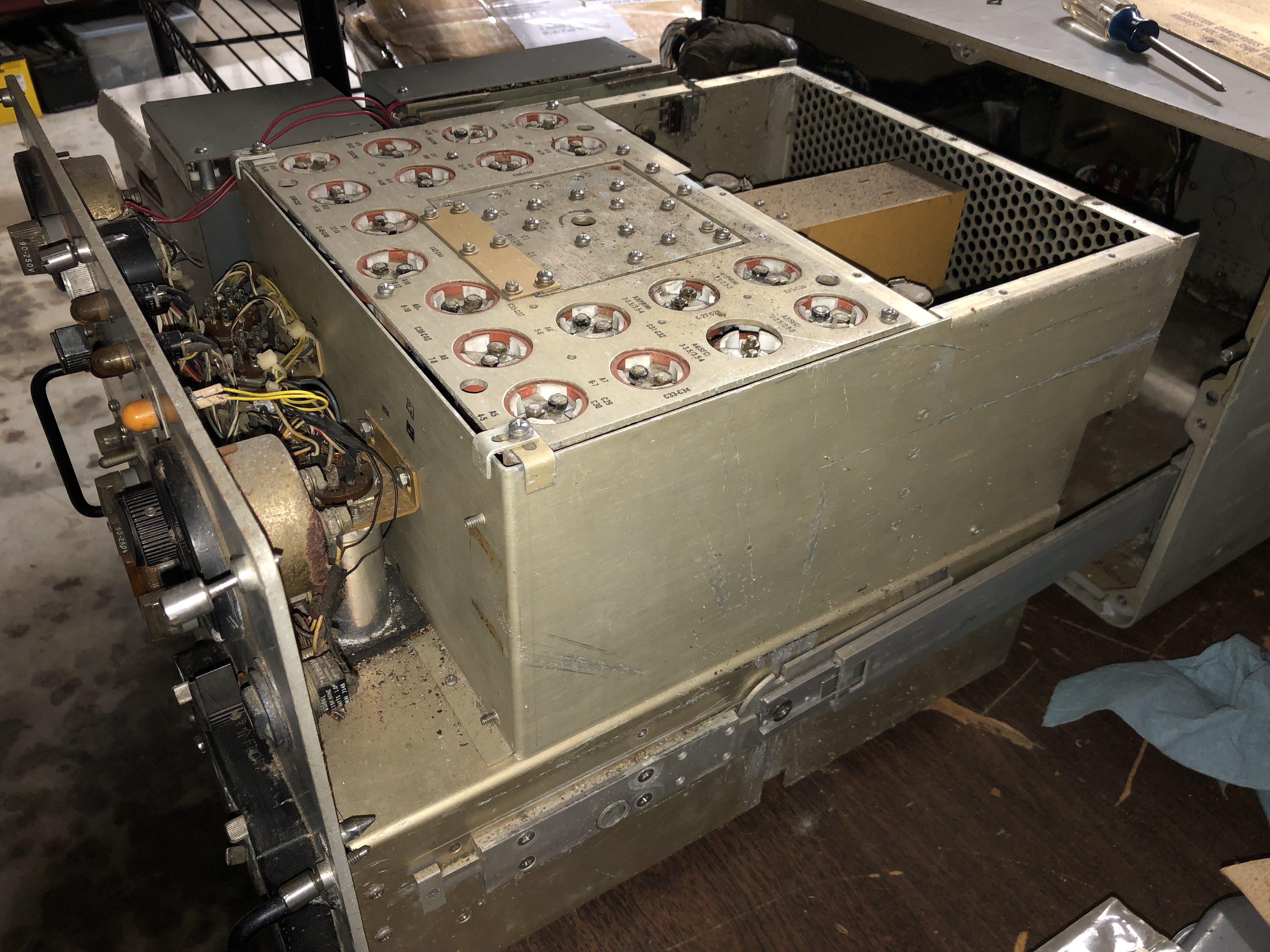
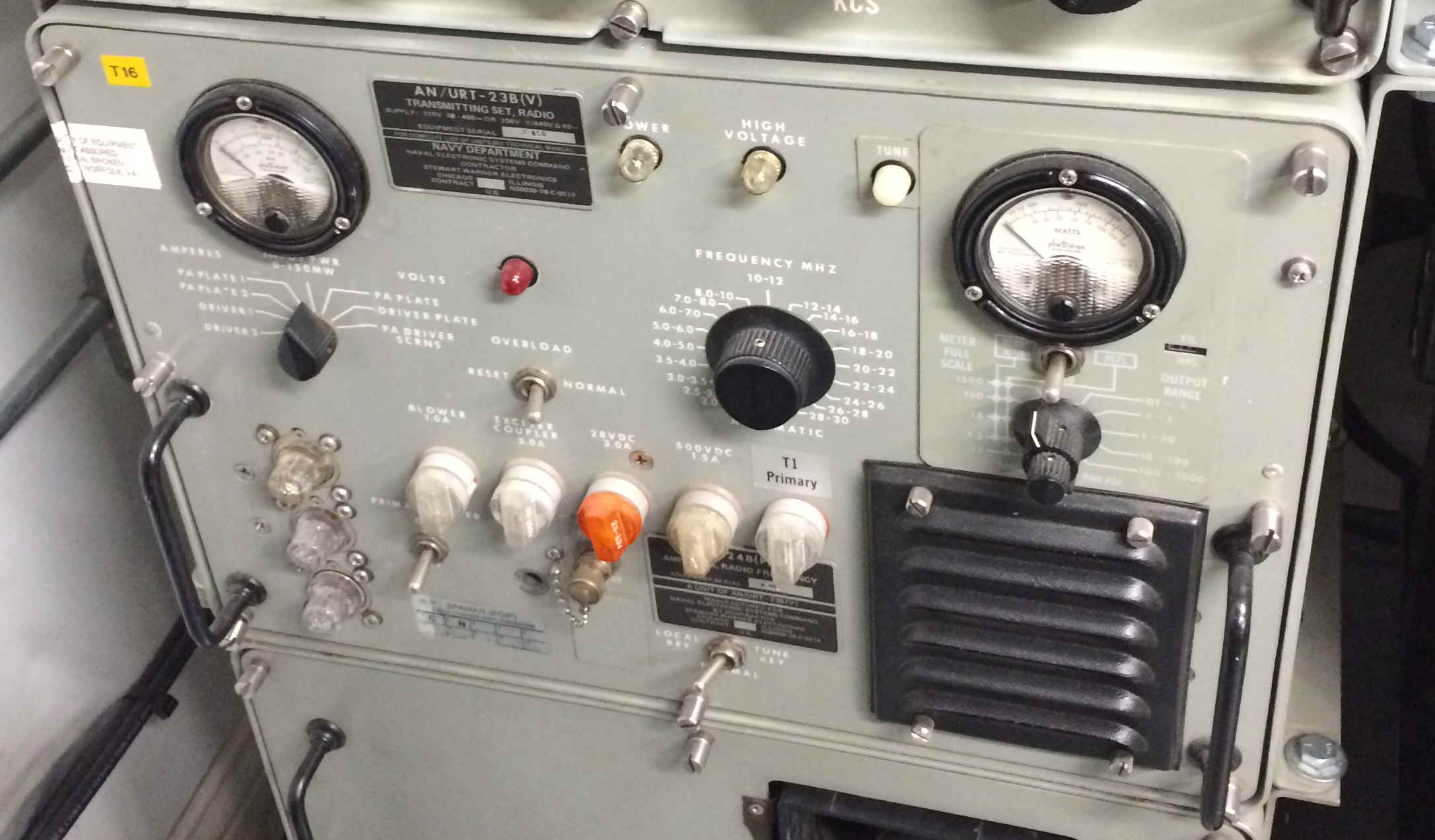
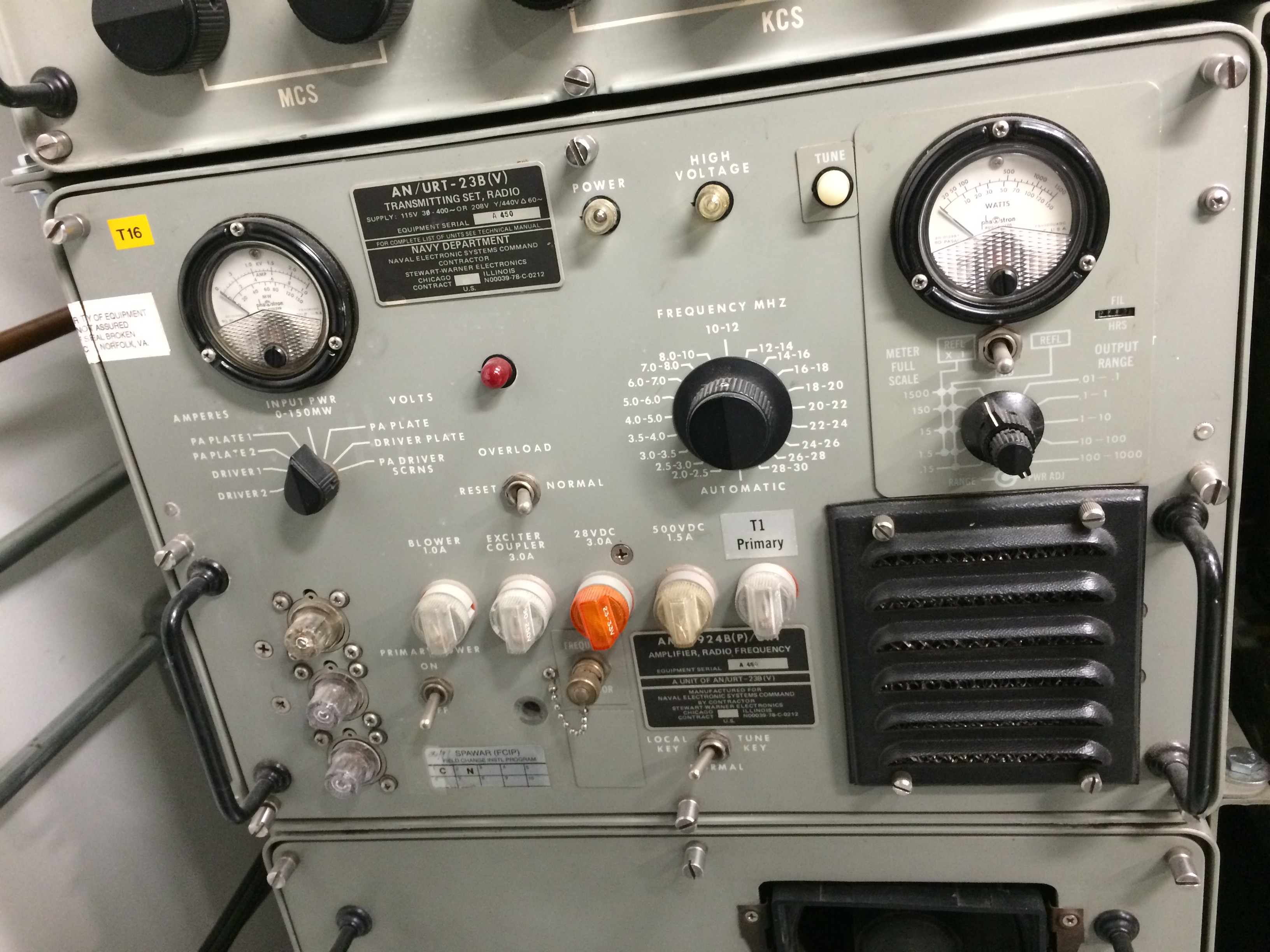
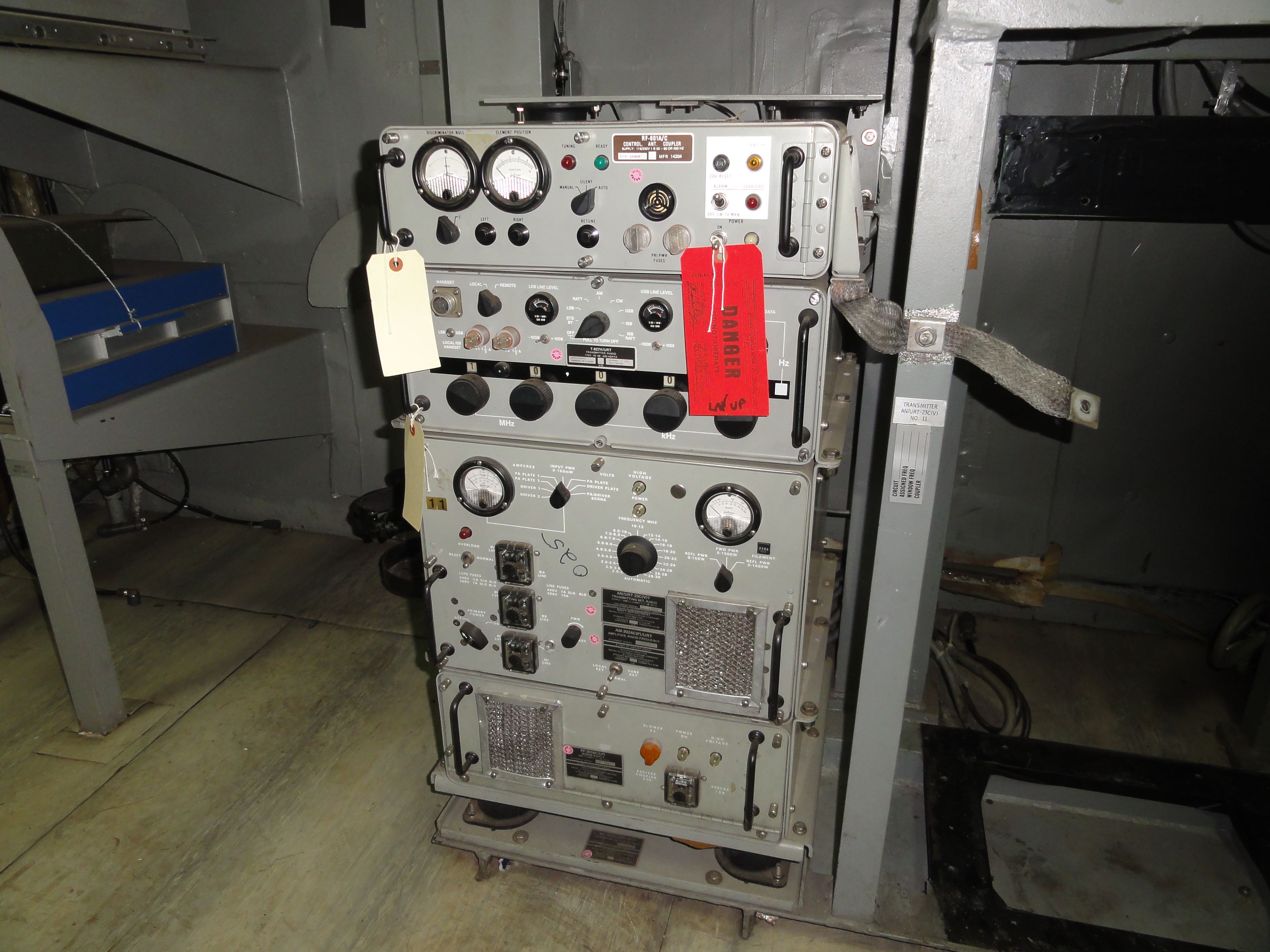
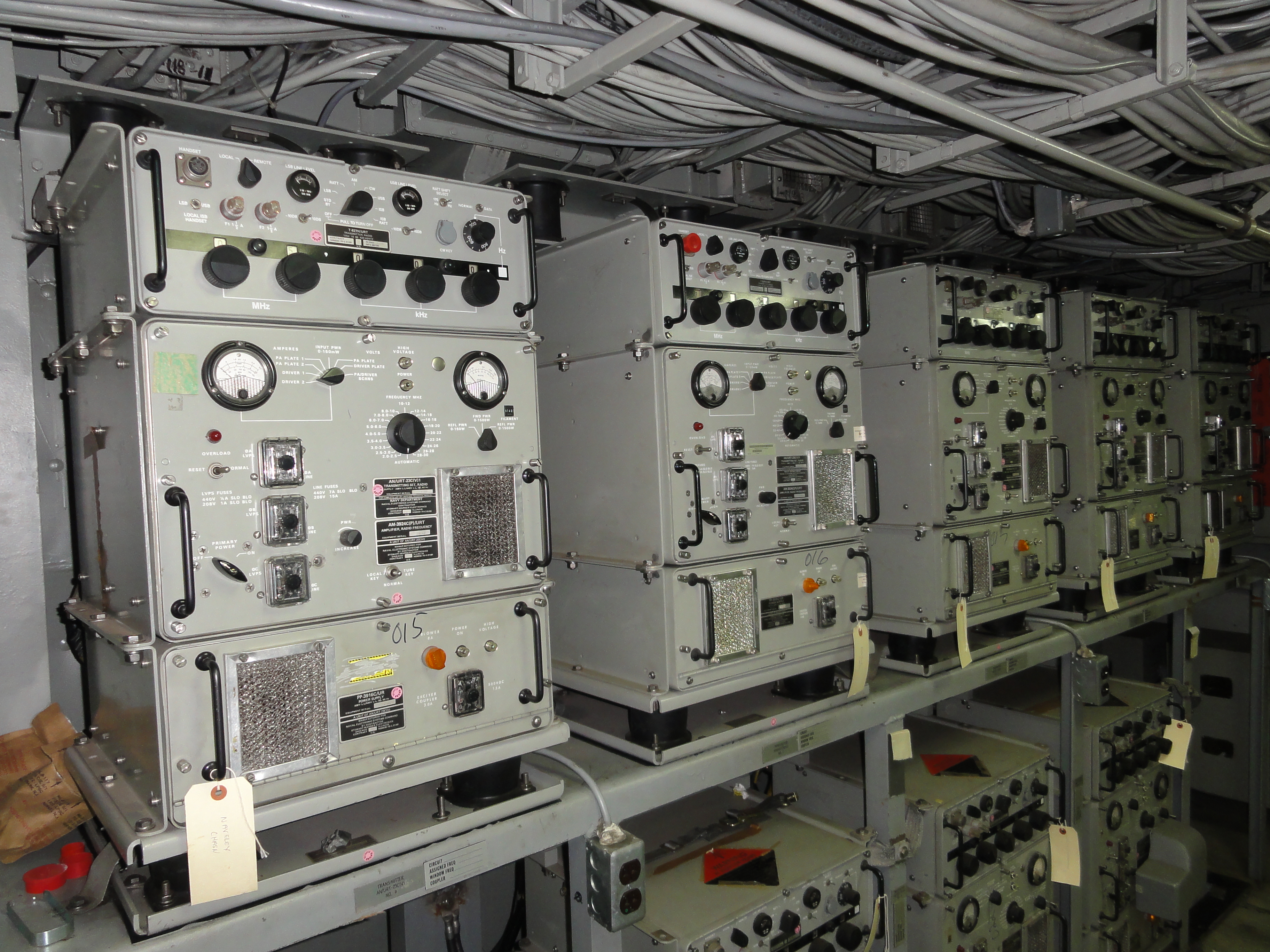
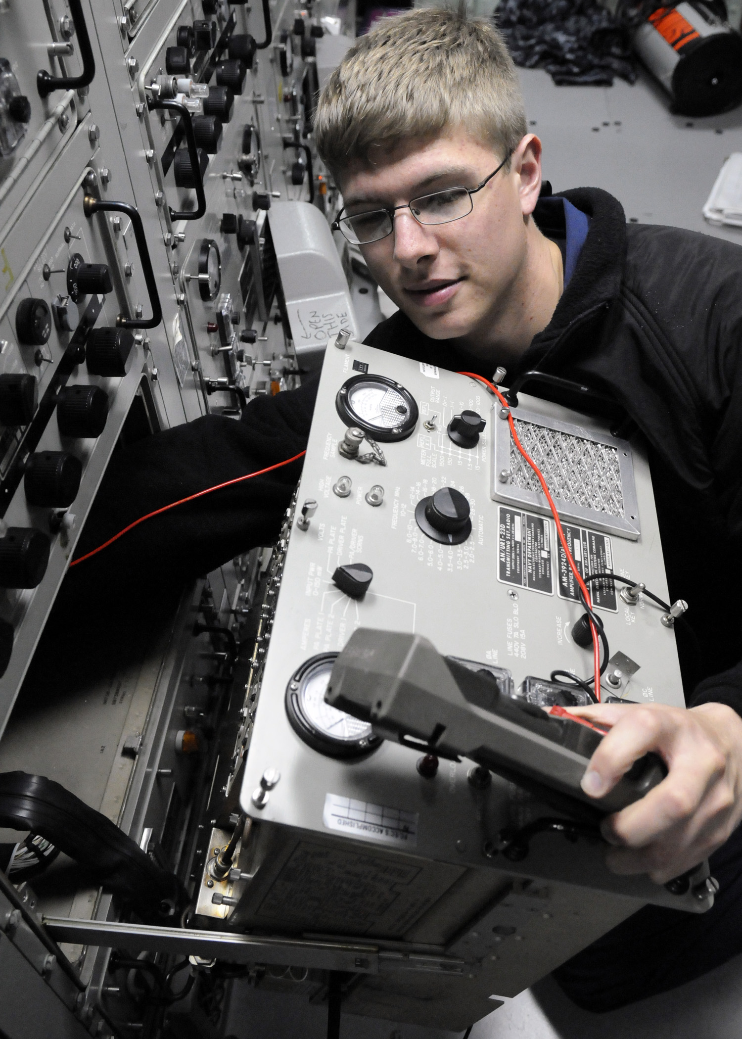
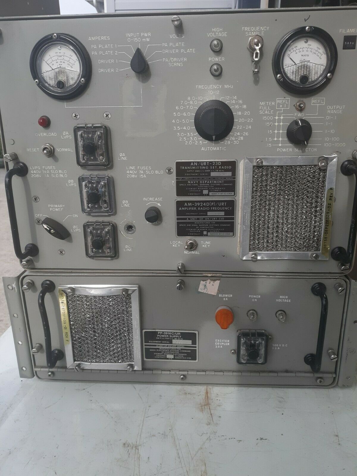
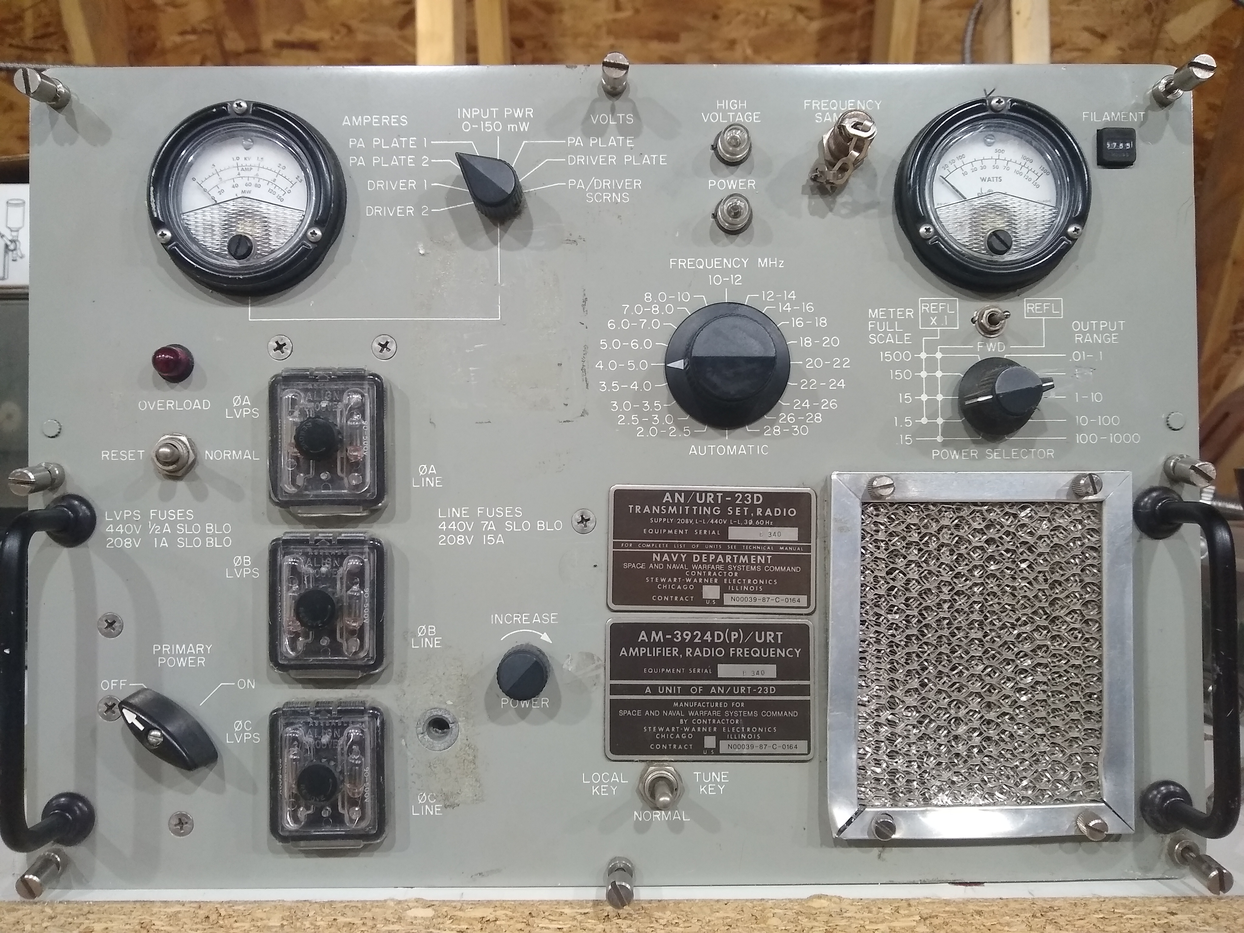
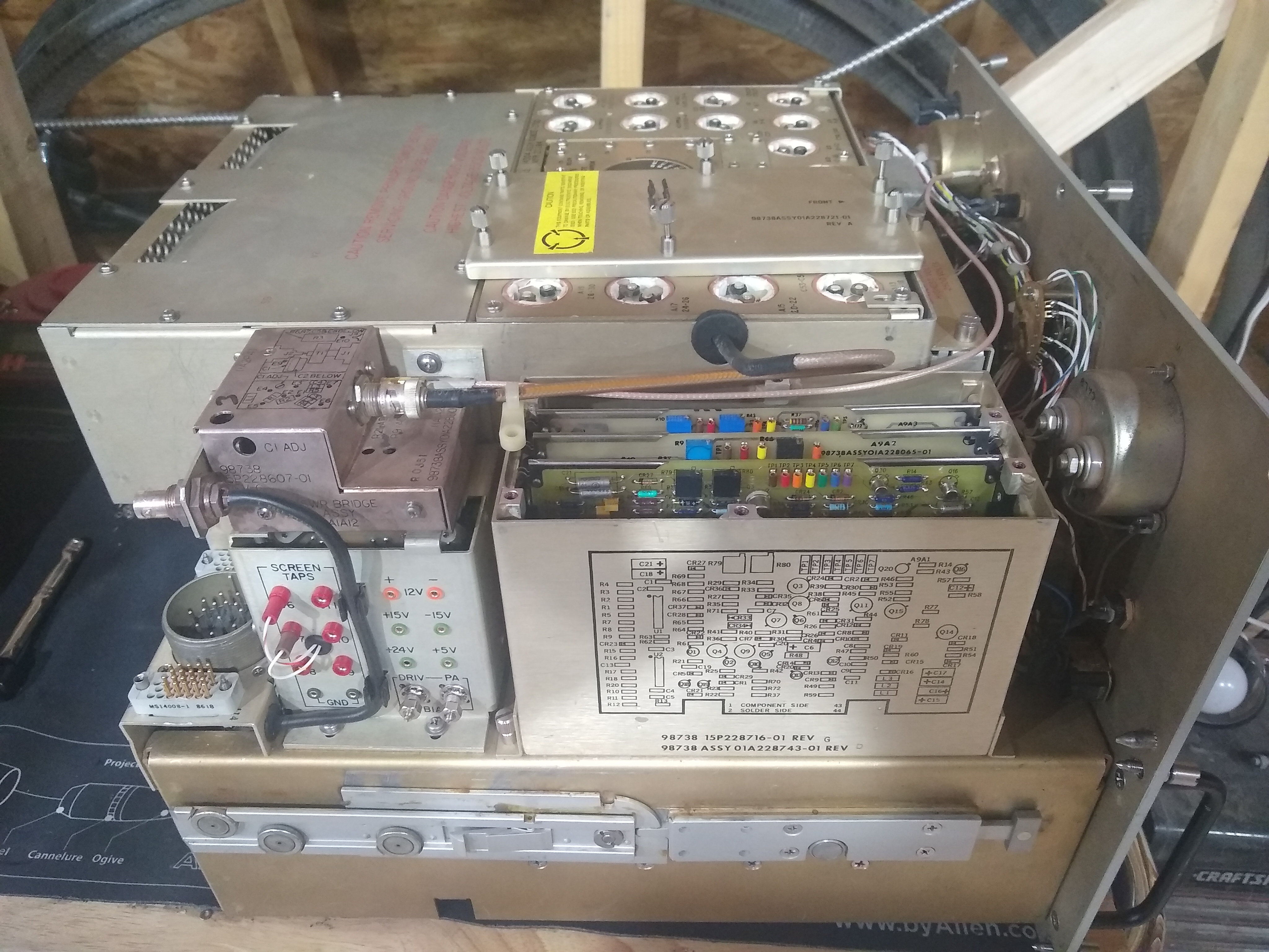
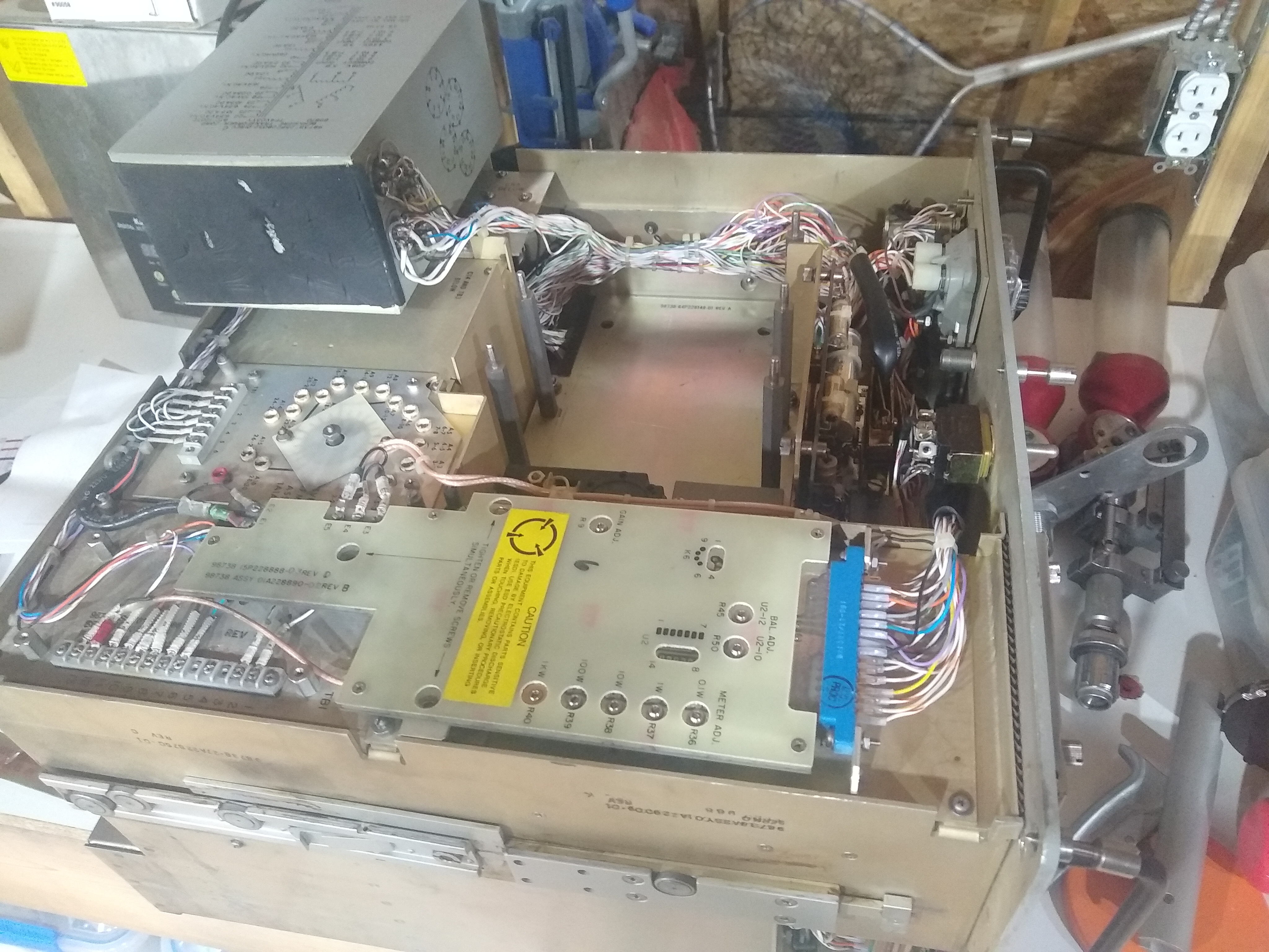
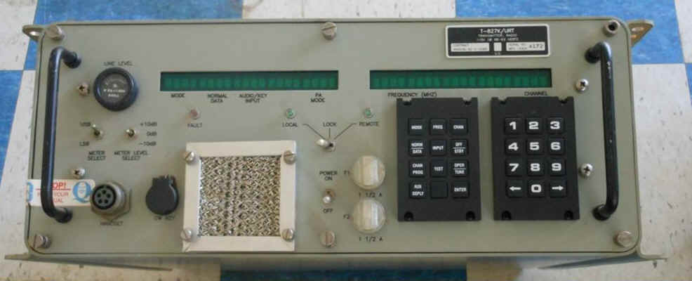
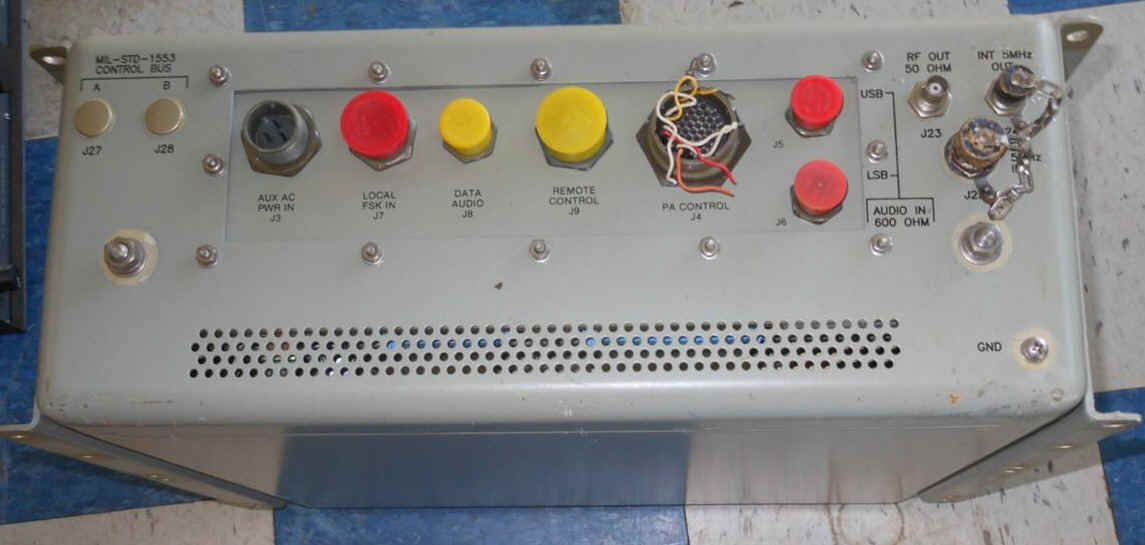
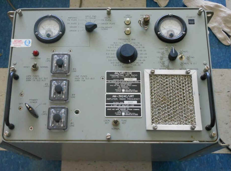
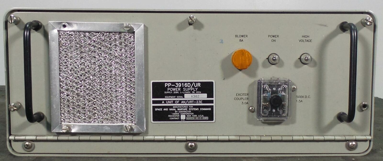
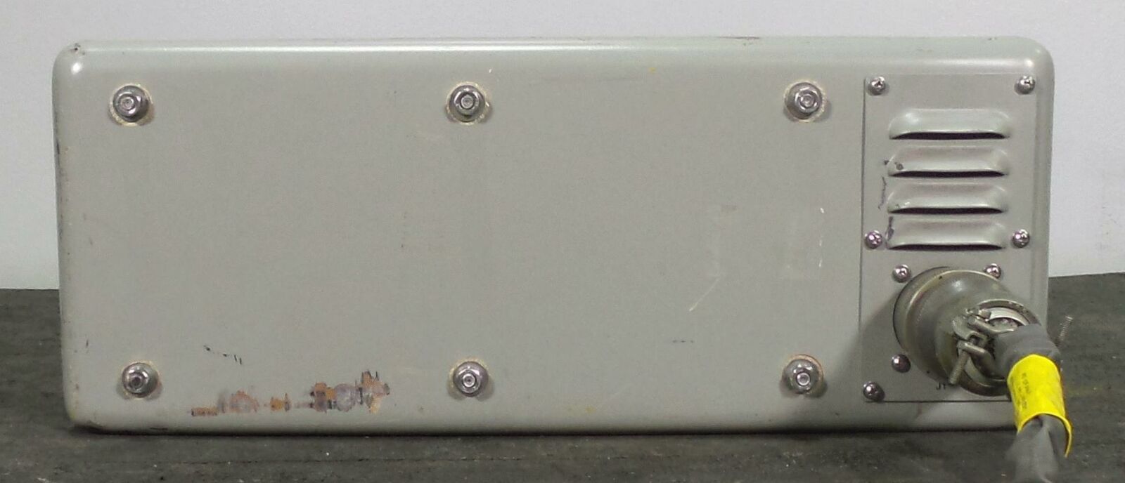
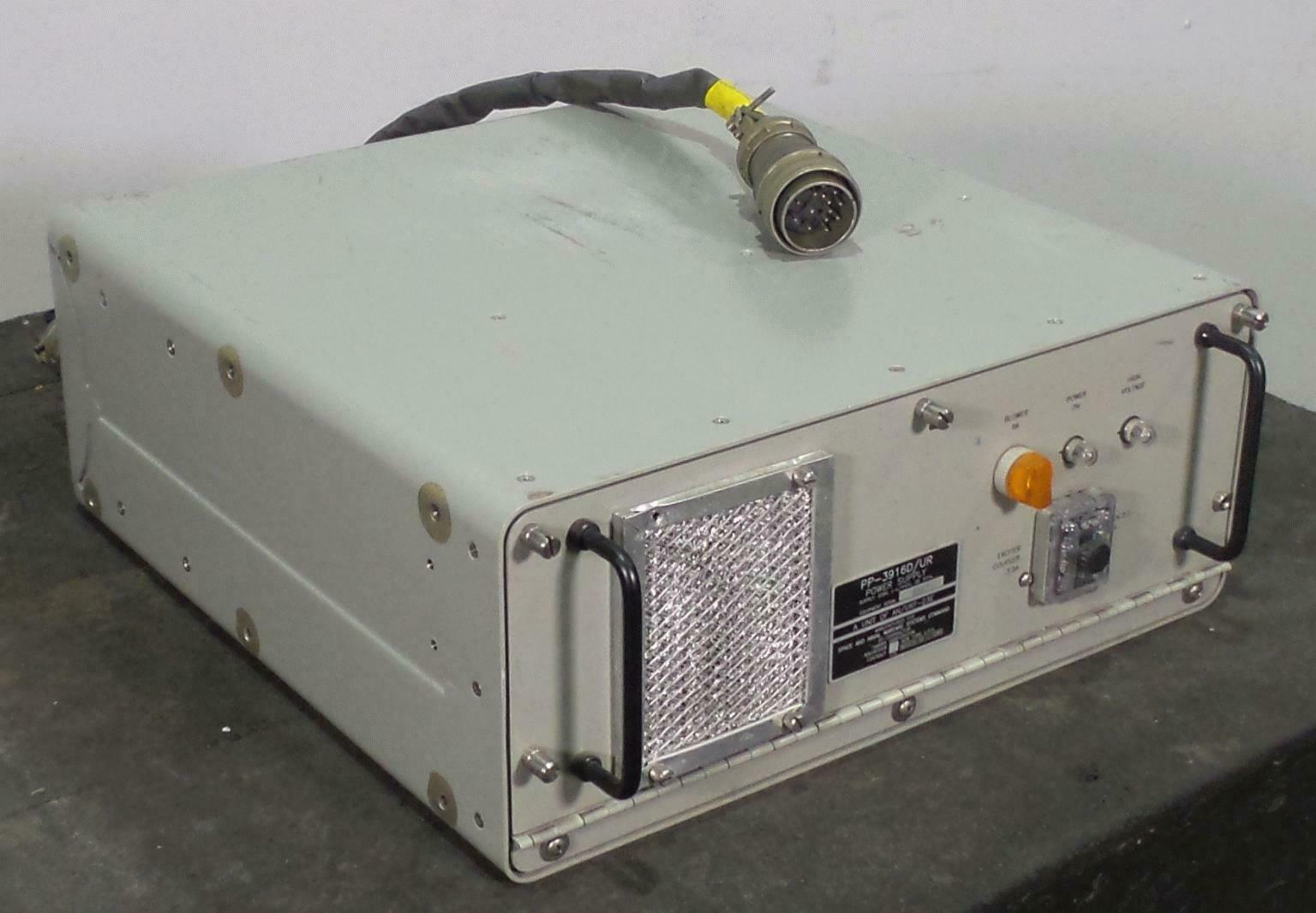
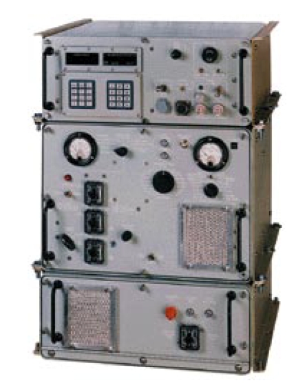
AN/URT-23 Transmitter - includes T-827B/URT, AM-3924/URT, PP-3916/UR
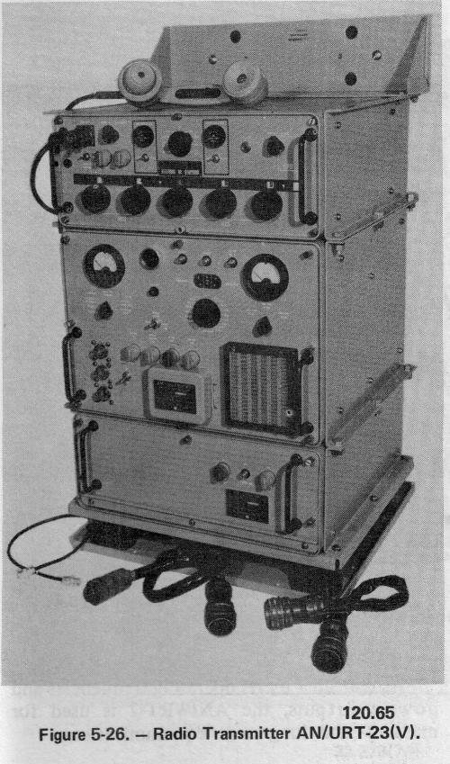
2-30mc,1kw
Components:
T-827B/URT - exciter
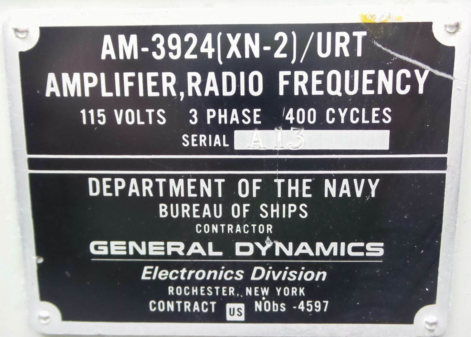
AM-3924/URT - RF amplifier
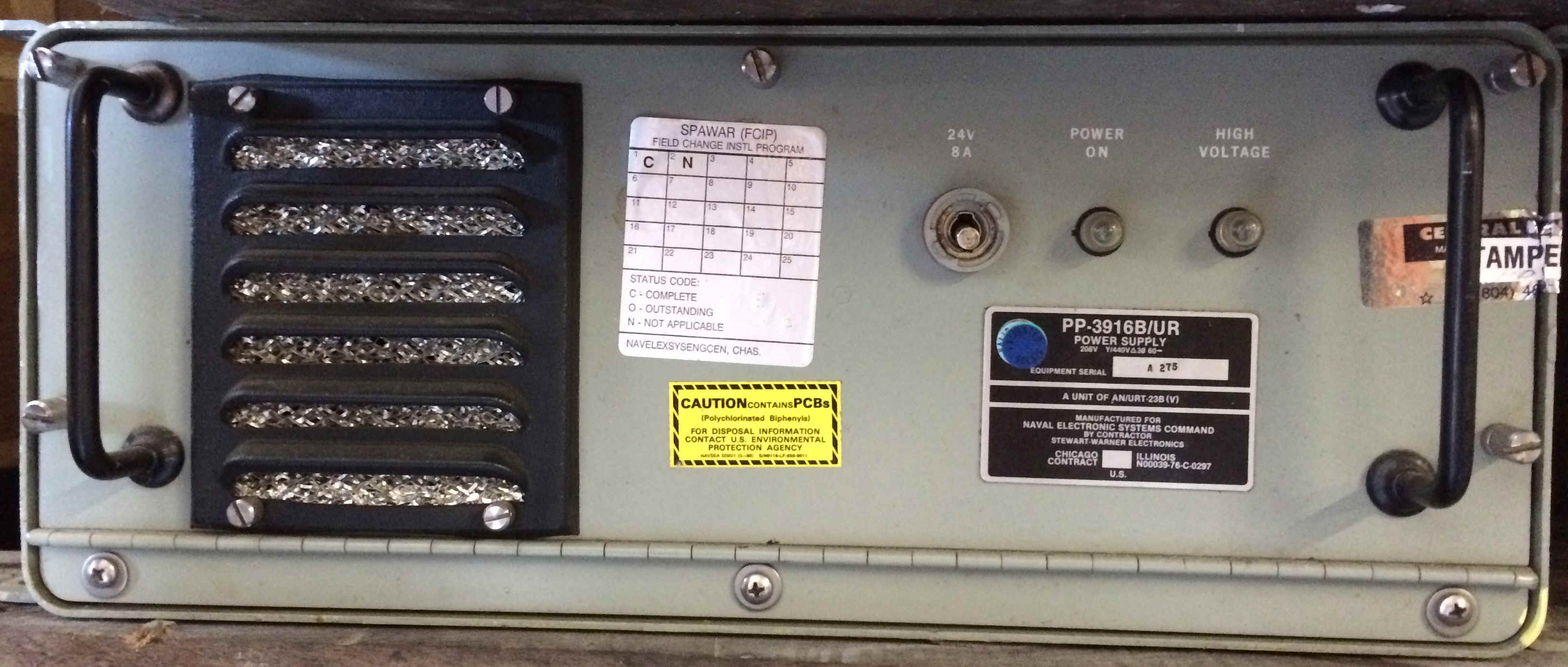
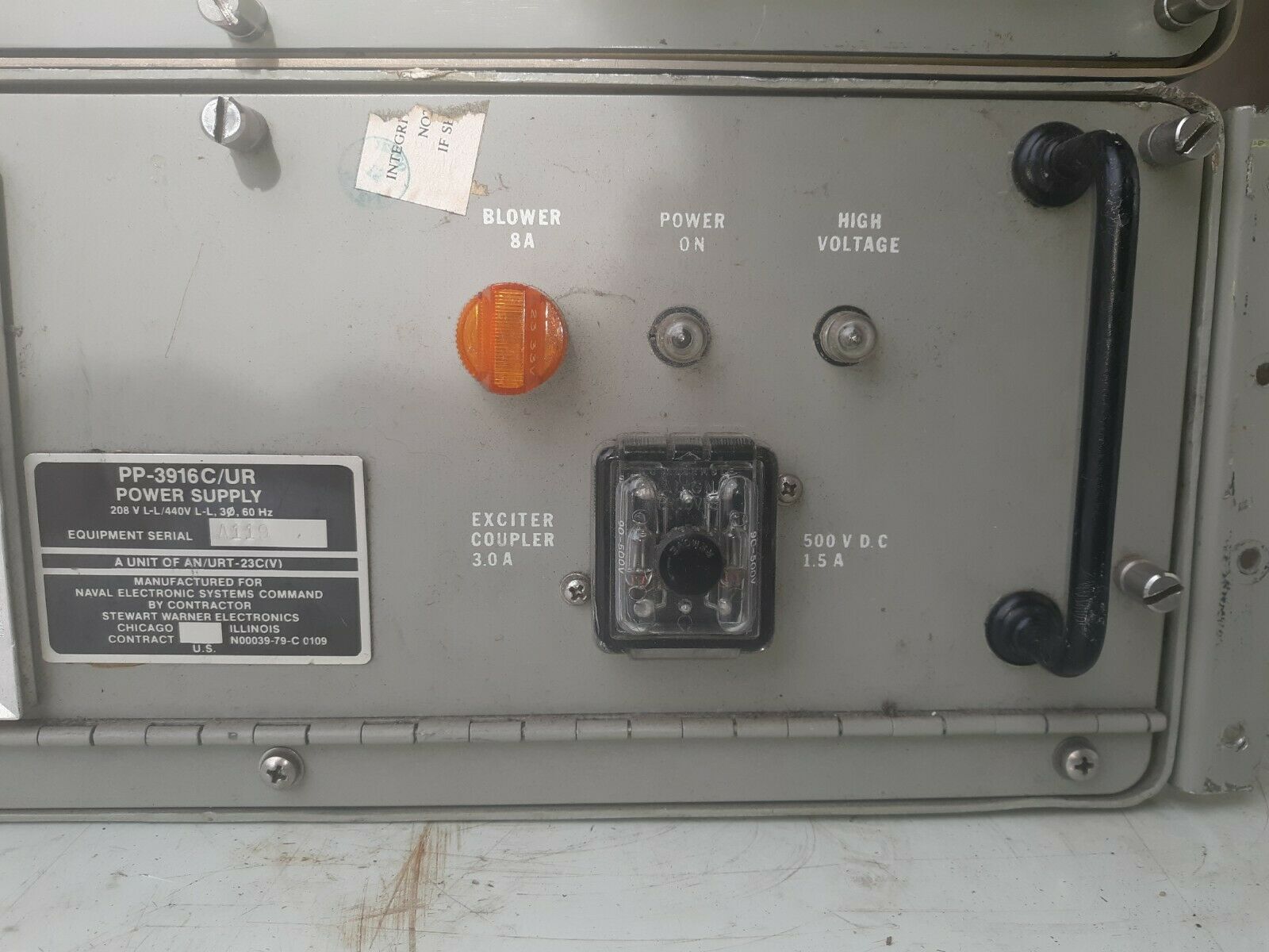
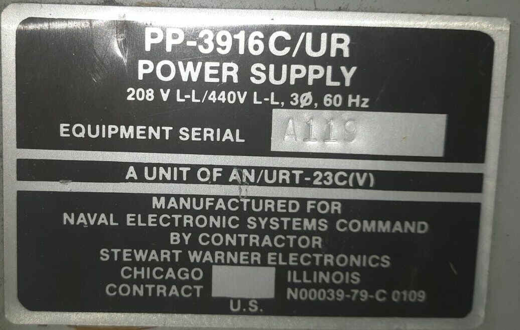
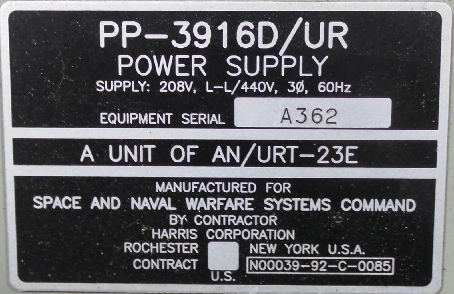
PP-3916/UR - power supply
MT-4670/URT-23 - shock mount
used with
AN/URA-38 - antenna coupler group
C-3698/URA-38 - controller
CU-938/URA-38 - coupler
AN/URT-23B specifications
T-827/URT model differences page
Predecessor - General Dynamics SC series equipment
- W8UT's Photos and Info
- Mil Spec MIL-T-28706F
- 12/69 manual download
- 6/79 manual download
- proposal for built-in 60 Hz supply
From CNO to CINCPAC 11/68
"The necessity for replacing the AN/SRT series transmitters with high
reliability equipment... is a matter of vital interest. The AN/URT-23 will
be available beginning in fiscal year 1970 for installation in the active
fleet."
- covers AN/WRC-1B and AN/URT-23(V)
Vol 3 part 2 - diagrams - download pdf
T-827/URT model differences page
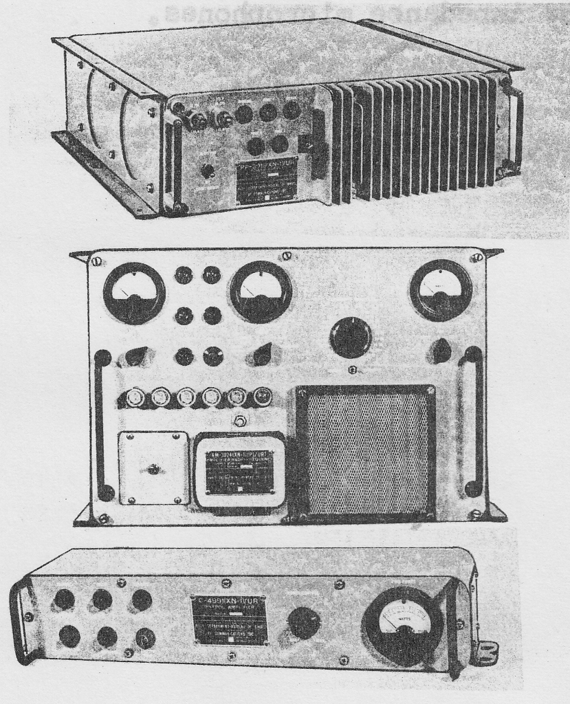
AM-3924/URT(XN-1) prototype
Includes C-4991(XN-1) remote
Version of RF-110
2 ea. 4CX350A + 2 ea. PL-8295A
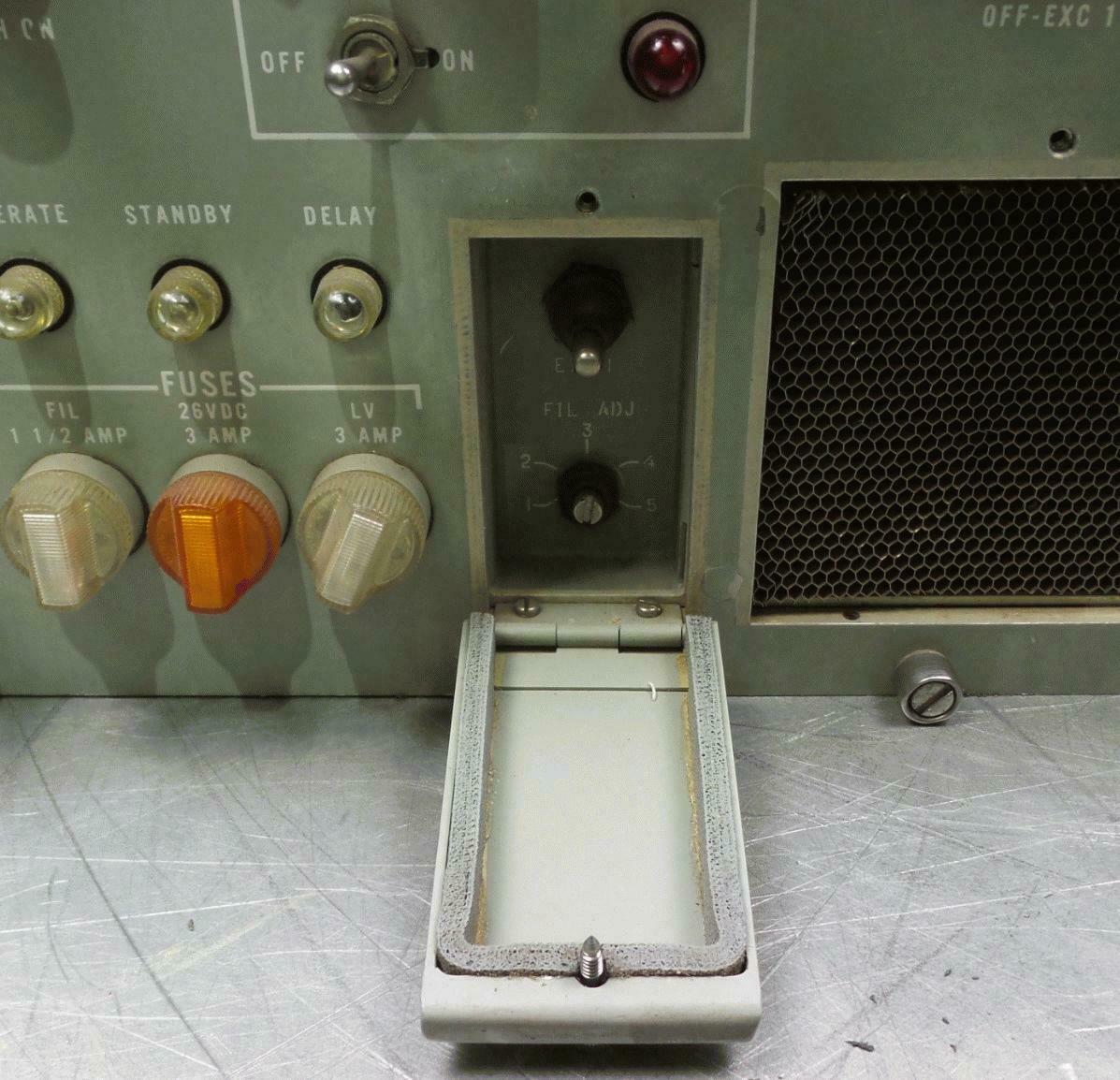
AM-3924(XN-2) prototype
(Version of SC-908A)
1 ea. 8117 + 1 ea. PL-8295
AM-3924 (AM-6909)
Version of RF-110
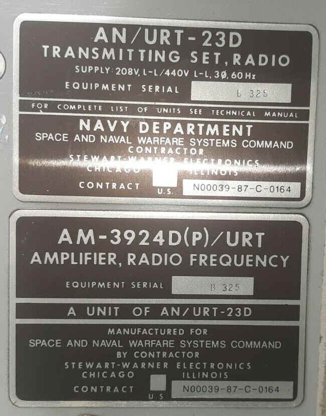
AN/URT-23B Transmitter - includes T-827G/URT, AM-3924B/URT, PP-3916B/UR (Stewart Warner)
AN/URT-23C Transmitter - includes T-827H/URT, AM-3924C/URT, PP-3916C/URT (Stewart-Warner)
AN/URT-23D Transmitter - includes T-827J/URT, AM-3924D/URT, PP-3916D?/URT
AN/URT-23E transmitter - includes T-827K/URT, AM-3924E/URT, PP-3916D/UR
T-827K/URT exciter

AN/URT-23F transmitter - includes T-827L/URT, AM-3924F?/URT, PP-3916D?/UR - Specifications
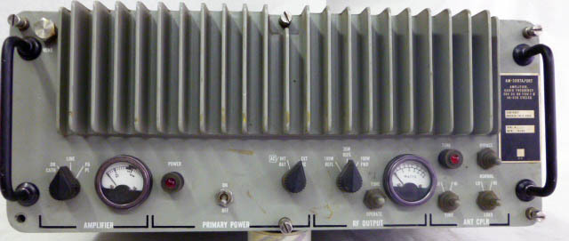
AN/URT-24 Transmitter
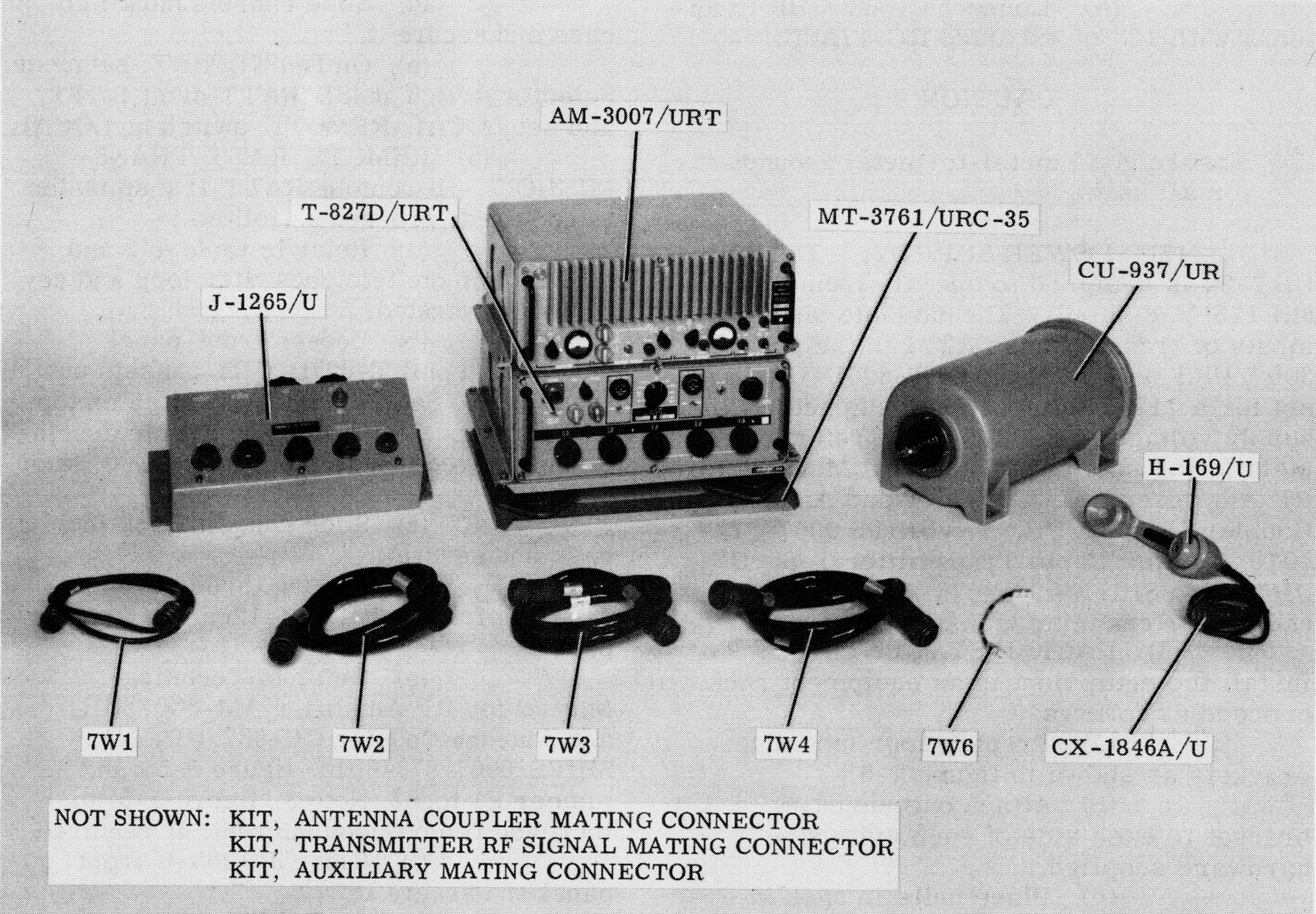
AM-3007/URT amplifier
J-1265/U junction box
CU-937/UR antenna coupler
100w output 2-30mc
Manual download
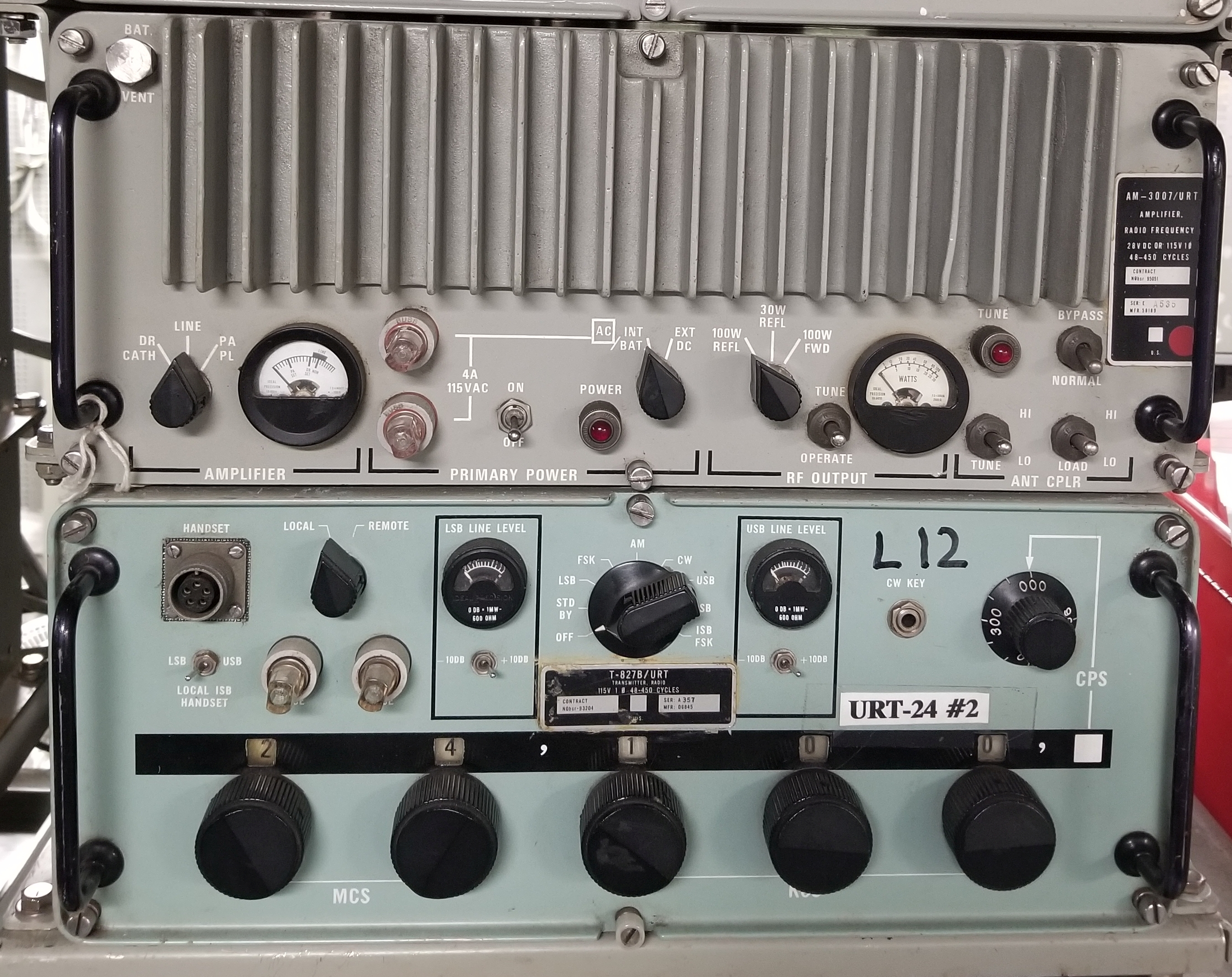
T-827B/URT exciter
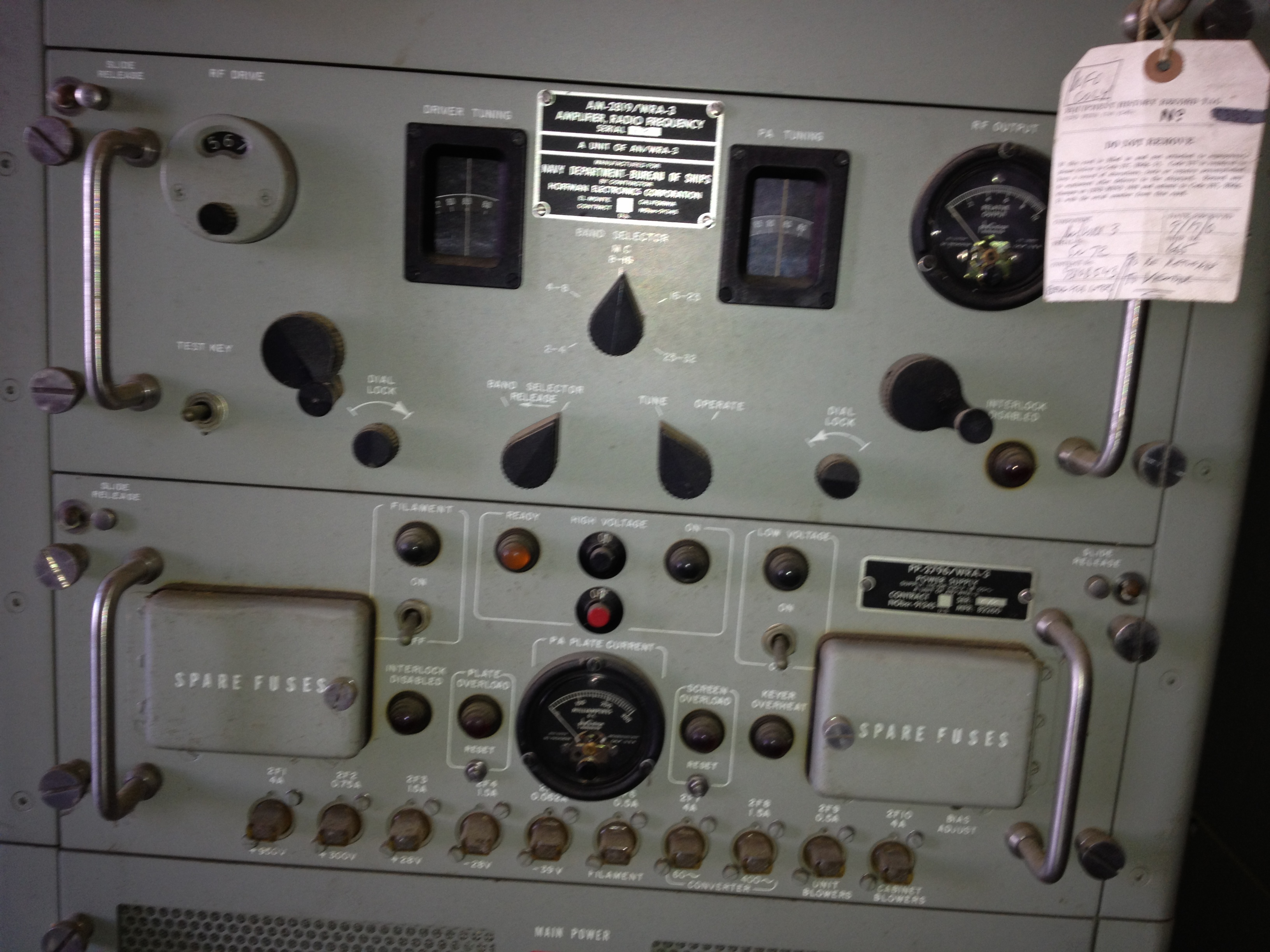
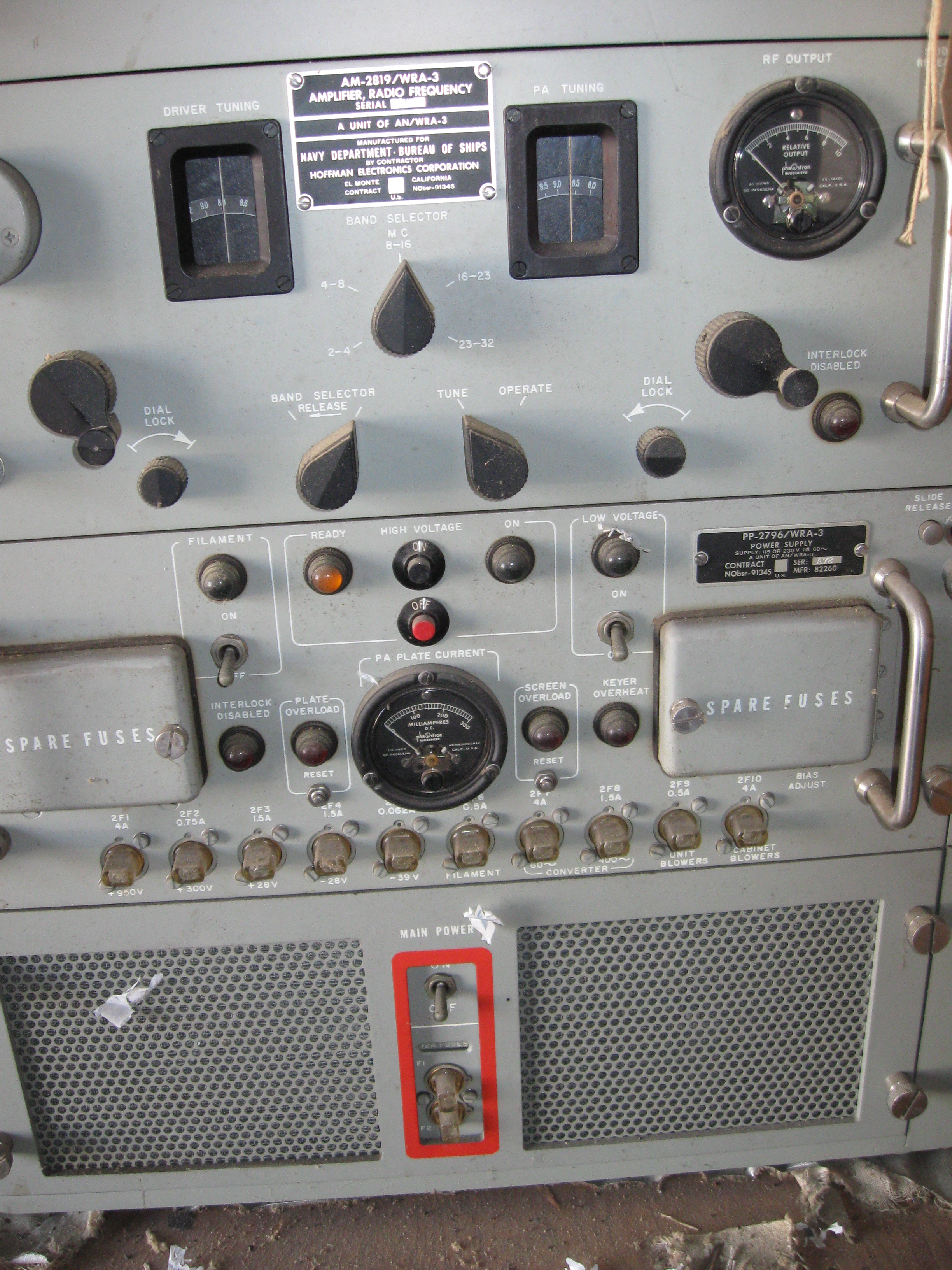
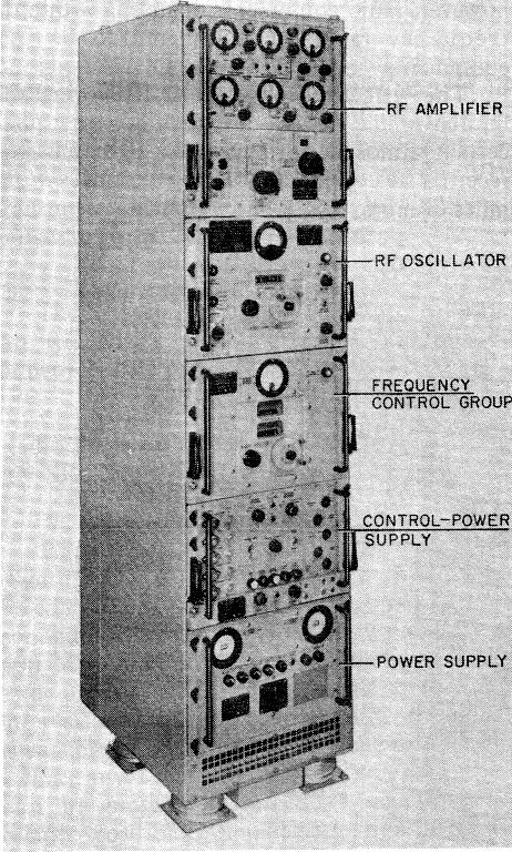
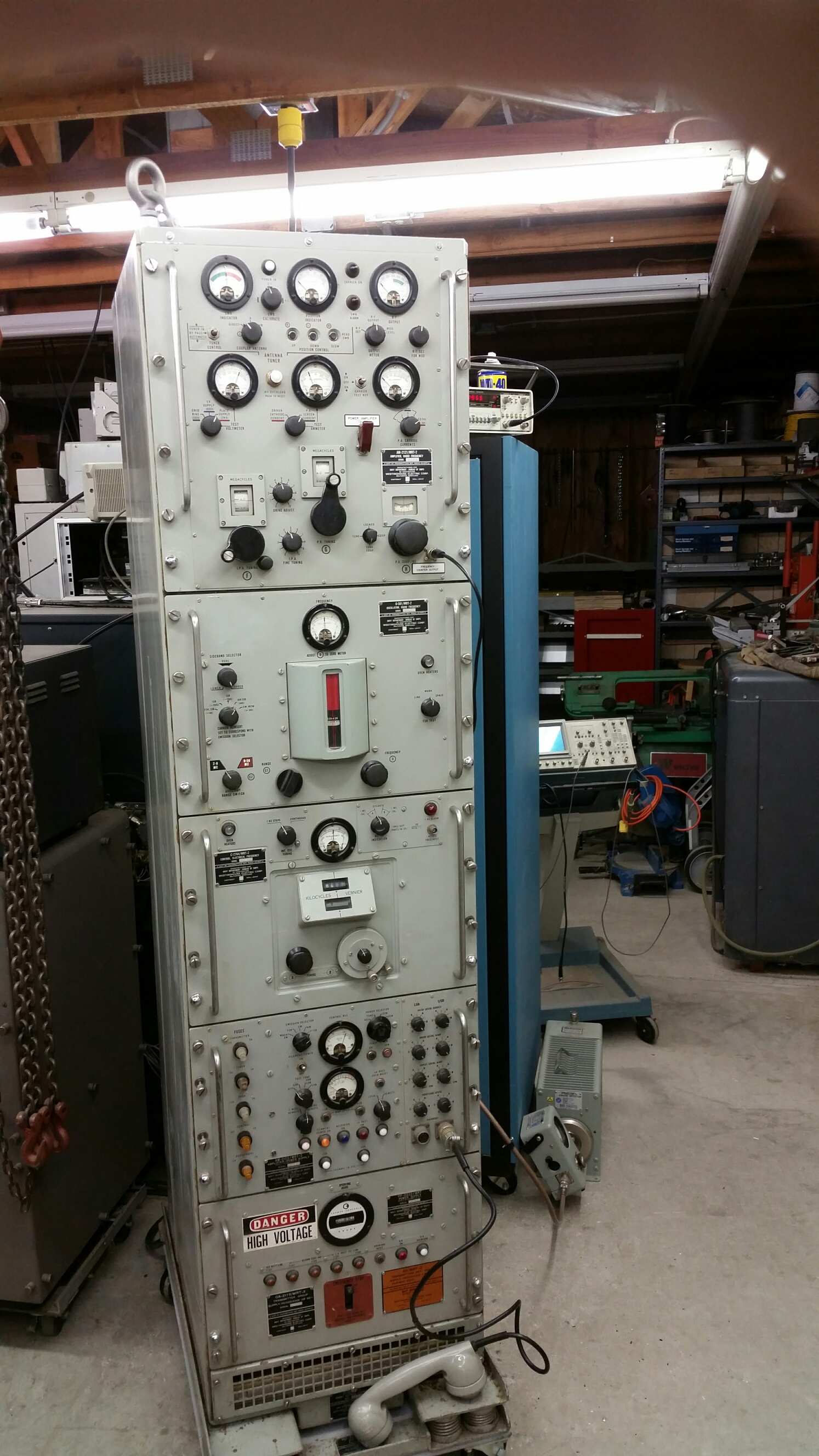
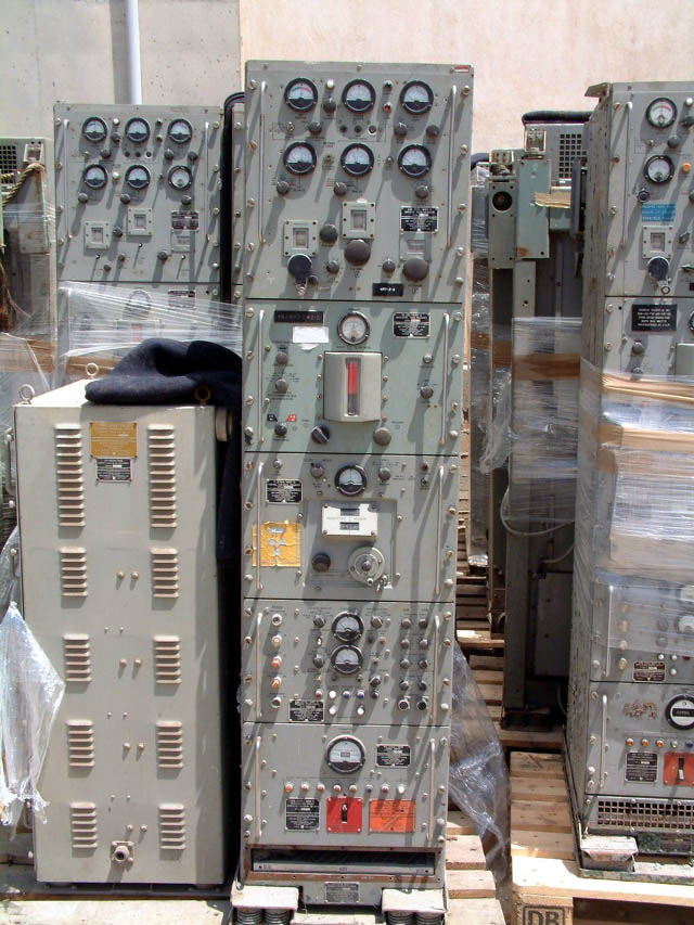
AN/WRA-3 HF exciter
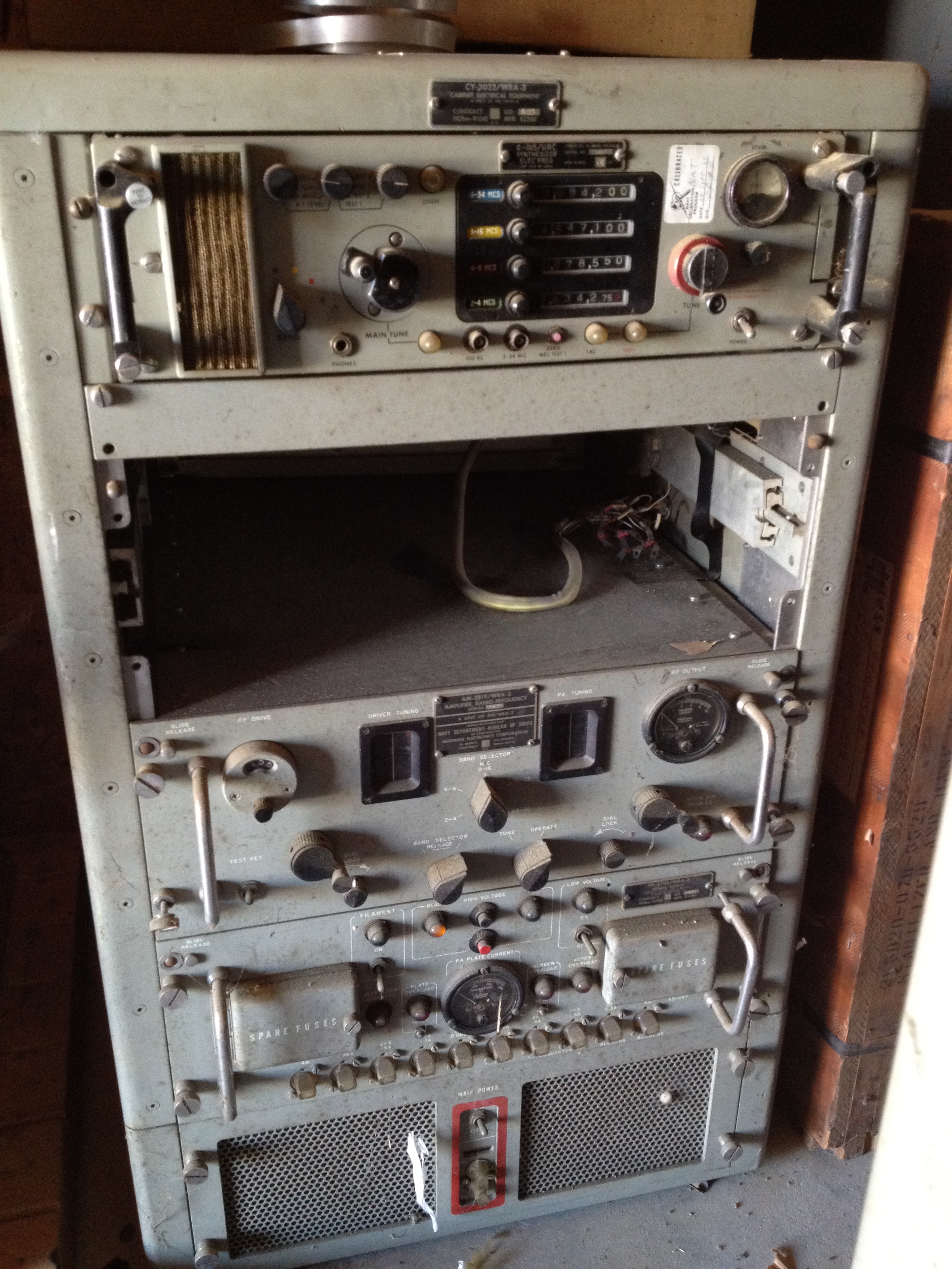
0.5w or 15w output
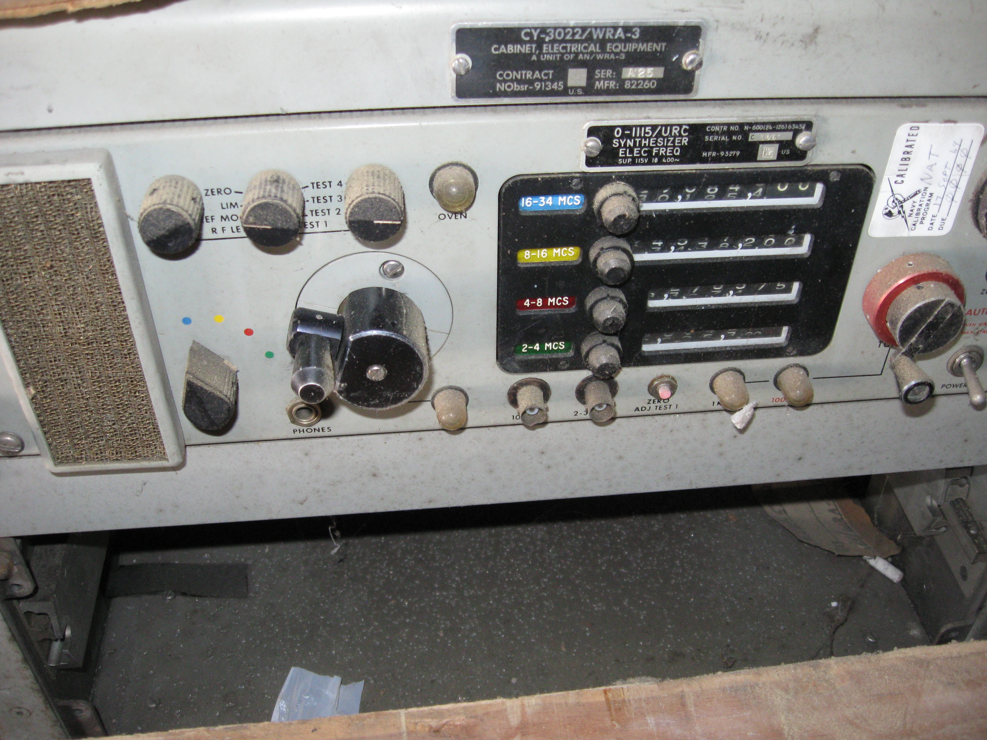
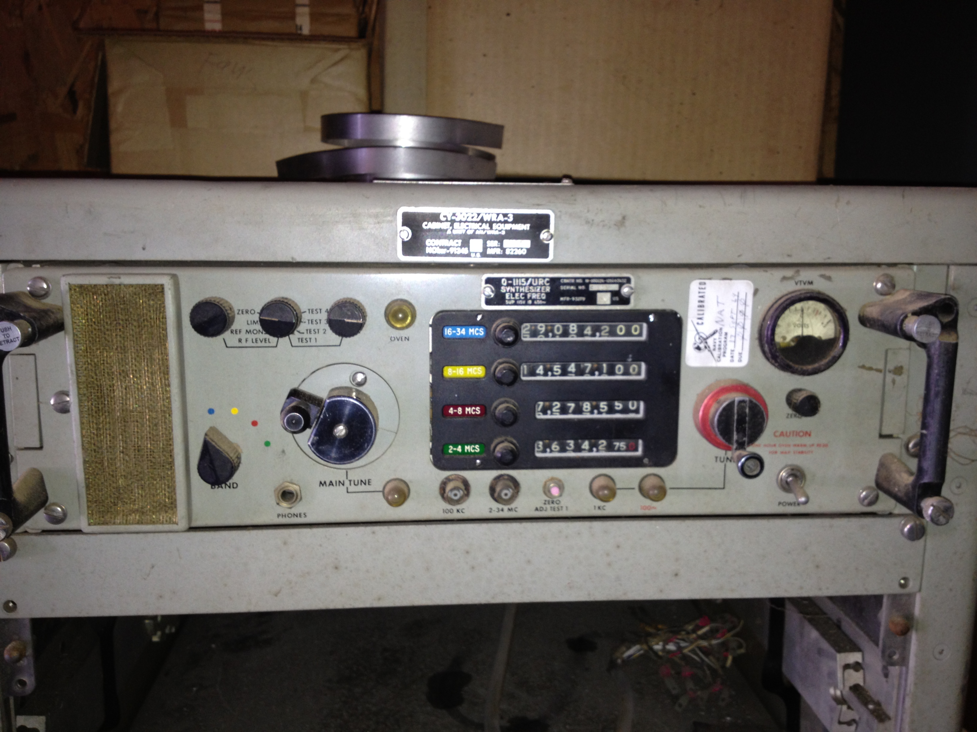
CY-3022/WRA-3 cabinet
O-1115/URC synthesizer
AM-2819/WRA-3 amplifier
PP-2796/URA-3 power supply
REFERENCE: Final Report on Project 0/S66 FY63 -
"Conduct an Evaluation of the AN/WRA-3 Radio Transmitter"
11 April 1963, SECRET
AN/WRT-1
AN/WRT-1A
LF Transmitter
125w AM
500w CW/FSK
Download 64.9 MB pdf
AN/WRT-2
Transmitter
500W CW, FSK, AM
1000w SSB/ISB
Click here for more WRT-2 photos
- -
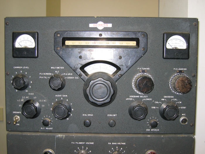
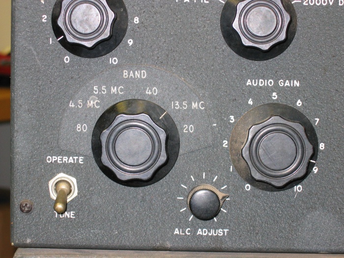
AN/WRT-4 Transmitter
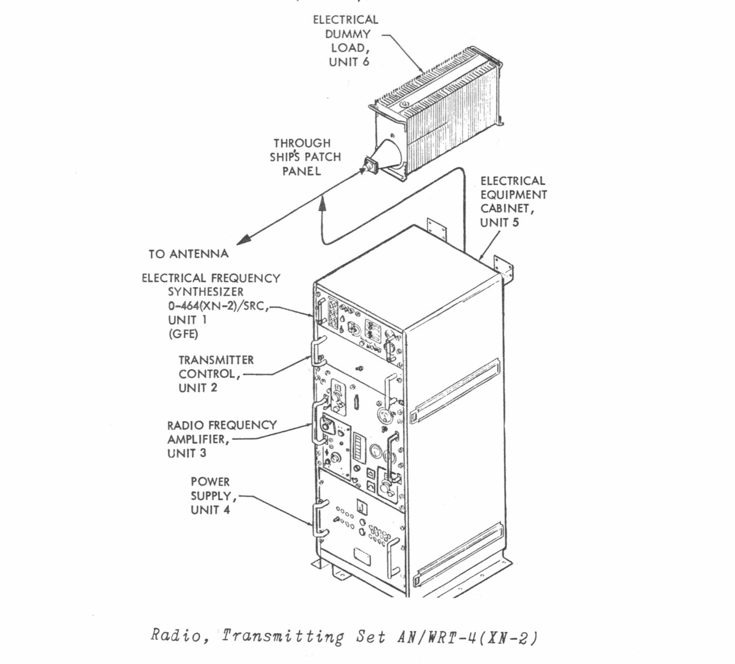
Collins KWS-1 Transmitter
photos thanks to K7DFW
Manual - NAVSHIPS 92787
Standard KWS-1 info page
3.0 - 4.0 mc
7.0 - 8.0 mc
14.0 - 15.0 mc
21.0 - 22.0 mc
26.4 - 27.4 mc
28.0 - 29.0 mc
29.0 - 30.0 mc
Navy version
3.0 - 4.0 mc
4.0 - 5.0 mc
5.0 - 6.0 mc
7.0 - 8.0 mc
13.0 - 14.0 mc
14.0 - 15.0 mc