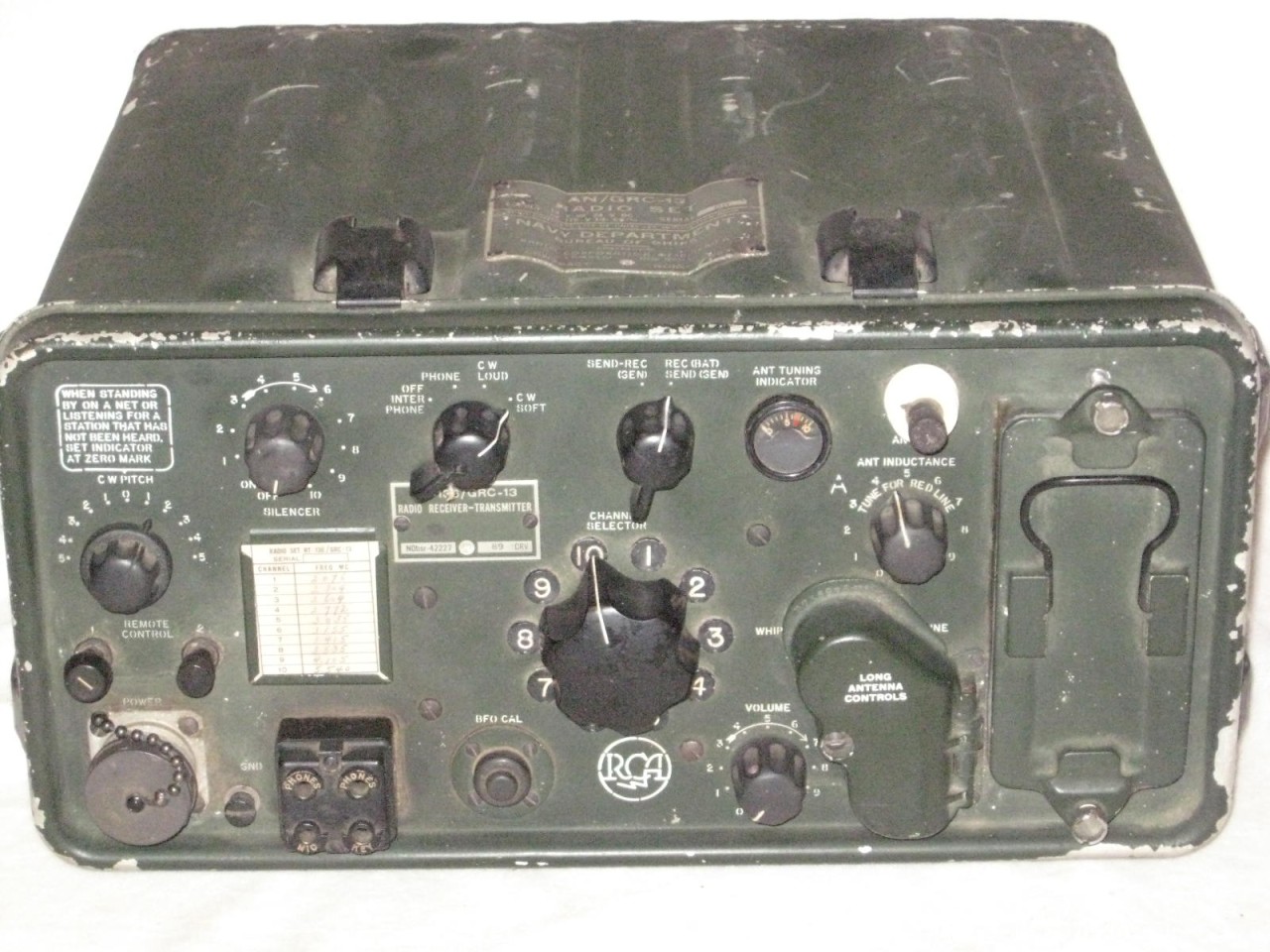
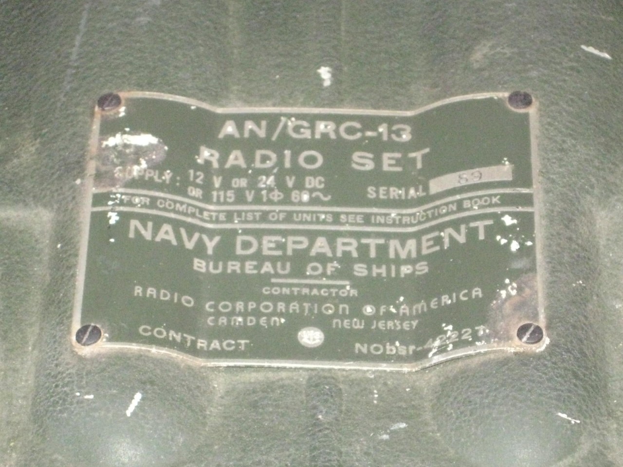
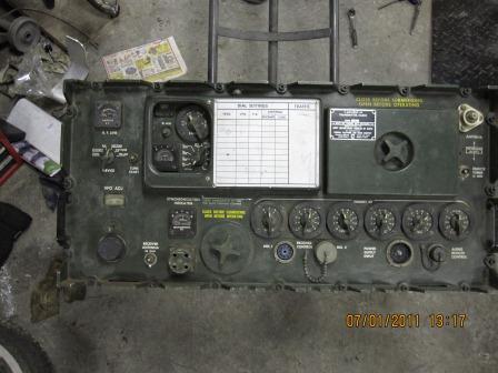
AN/GRC-13
RT-136/GRC-13
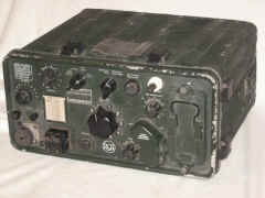
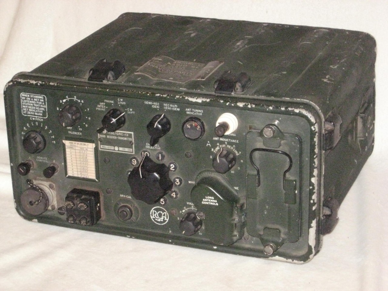
Made by RCA
Manual NAVSHIPS 91235
10 crystal controlled channels
15-20 watts output
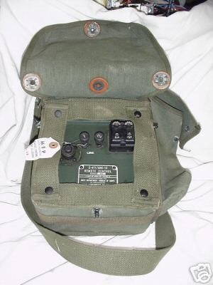
Legband NT-10531
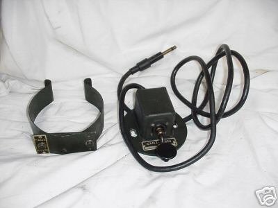
Headset NT-49507-A


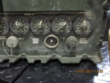
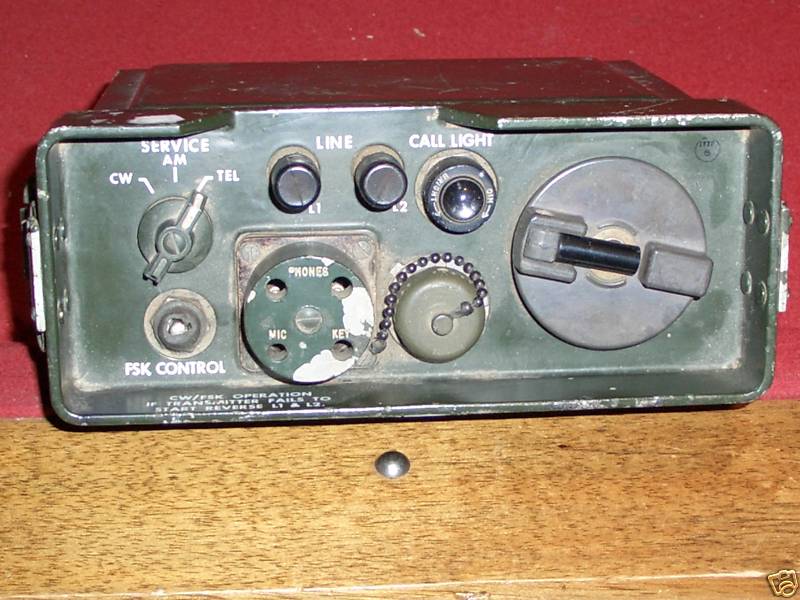
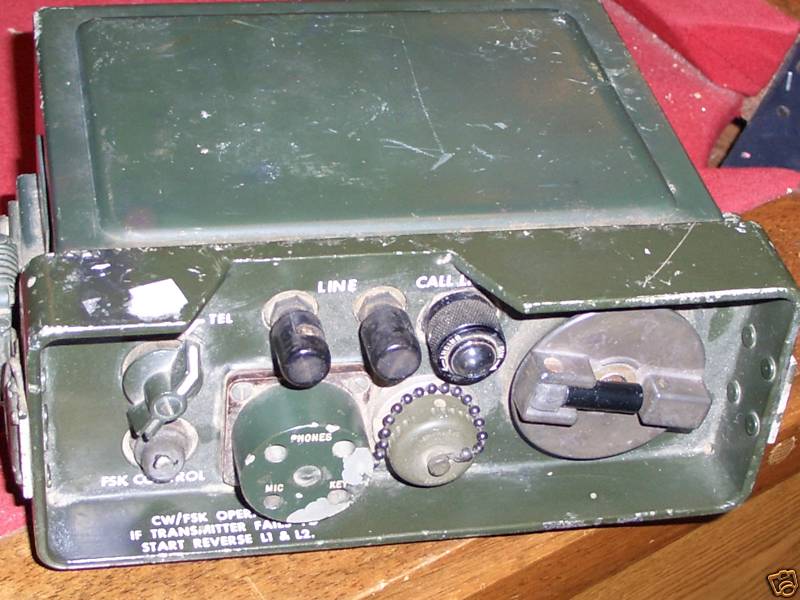
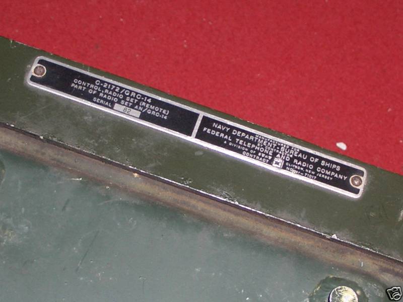
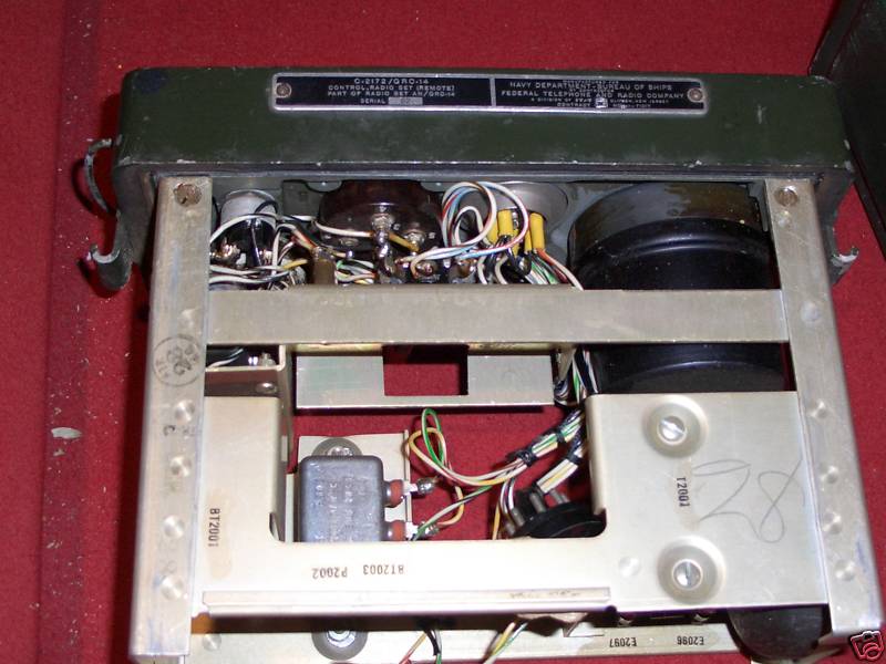
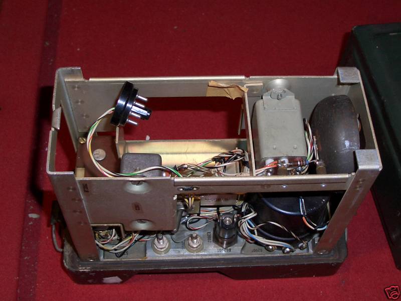
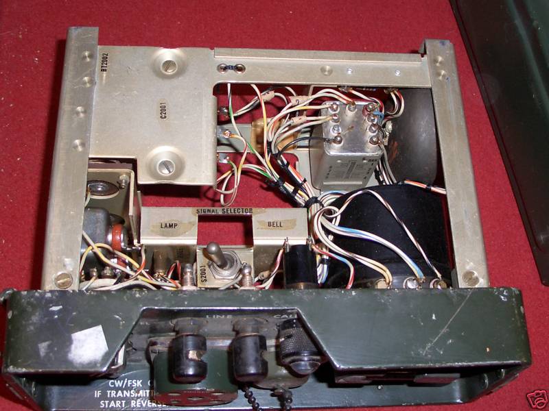
AN/GRC-14
part of AN/MRC-55 Jeep
2-20mc 400W, AM/CW/FSK
made by ITT Federal
NAVSHIPS 92911(A)
Technical Description
T-631/GRC-14
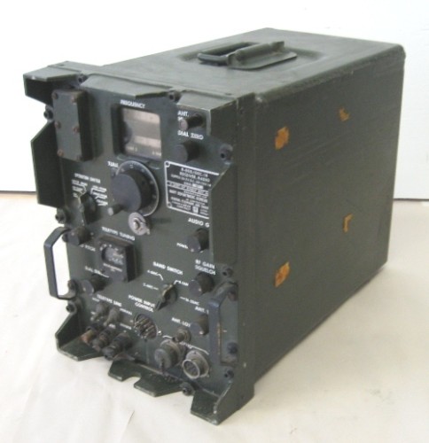
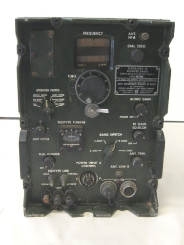

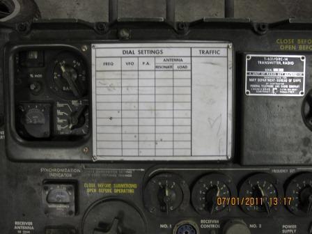
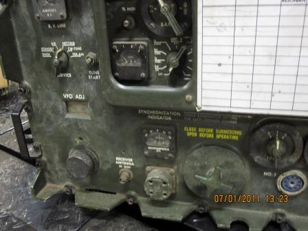


AN/SRC-16 Transceiver System (4 rcvr-xmtr units)
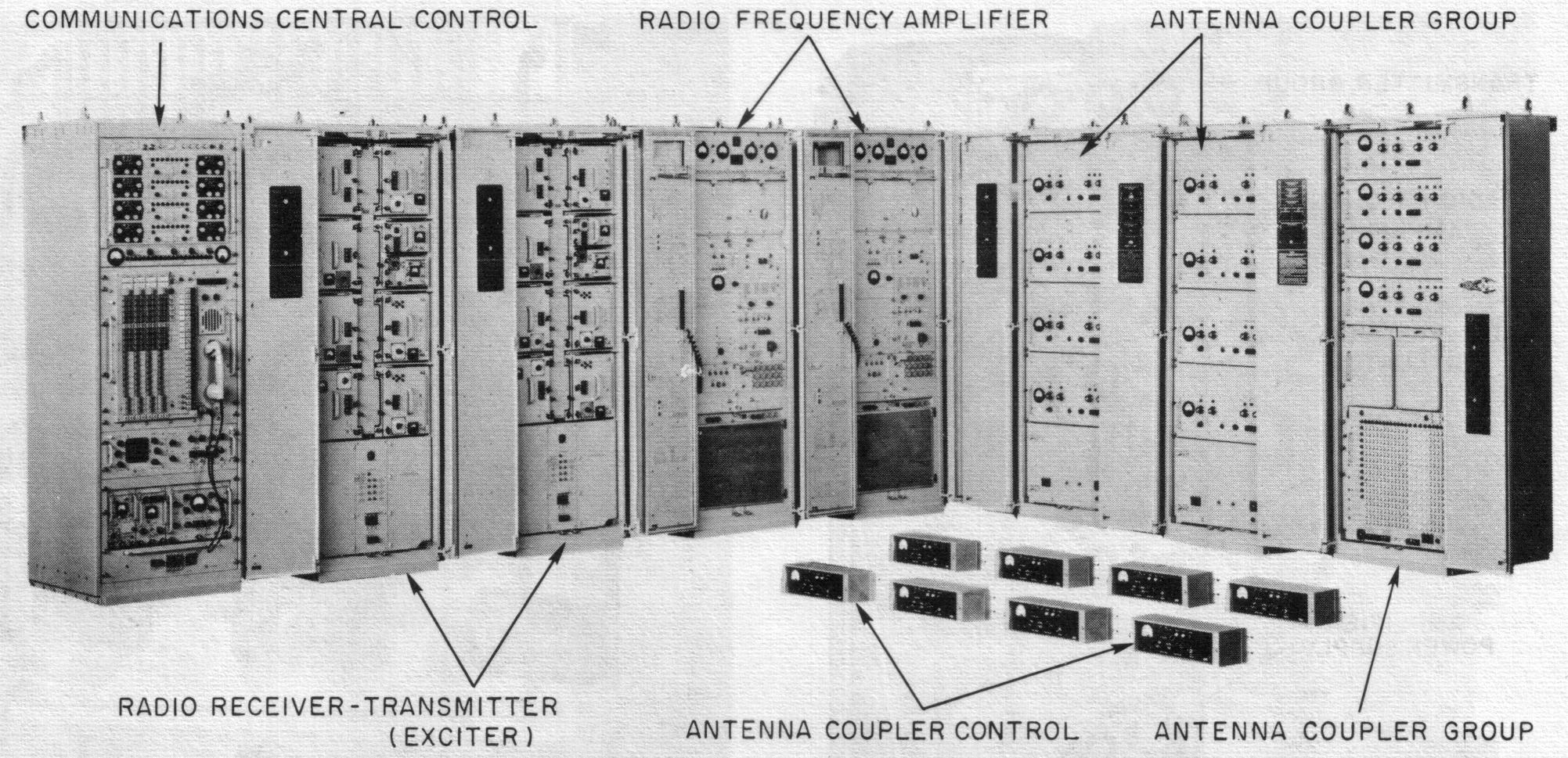
AN/SRC-16 Specifications (from 1964 Collins catalog)
AN/SRC-16
Checkout/Maintenance Manual
- thanks to Francesco K5URG
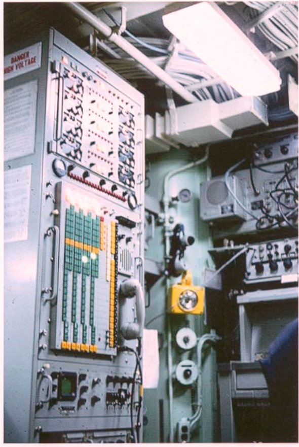
SRC-16 Communications Central Control aboard DLG-33
photo thanks to W5JV
4 independent rcvr-xmtr channels
2-30mc, SSB/CW/NTDS, 500w PEP per channel (plus two 5KW amps)
- CIRCUIT FEATURES - Linear power amplifiers, high performance filters and low distortion circuitry meet all complex data transmission and reception performance requirements. Compatible AM is transmitted using the upper sideband and a reinserted carrier. Pi network output circuitry assures efficient antenna loading. The converter for FSK-CW mode reception includes an oscilloscope to monitor test tones and to facilitate BFO adjustment on FSK reception.
- RF LEVEL CONTROL - A variable attenuator, using transistor circuitry, provides automatic control of radiated or received power levels. The RF signal between the transmitter and RF amplifier can be attenuated up to 120 db. Normally, it is automatically controlled by direct current pulses. It can be switched to the receiver input to manually attenuate the RF signal level.
- ANTENNA SWITCHING - The AN/SRC-16 employs 12 automatic antenna couplers with terminations for three or more antennas. In a typical installation, eight couplers are associated with the 2-6 me antenna, two couplers with the 5-15 me antenna and two with the 10-30 me antenna. Other arrangements are optionally available to meet individual system requirements. An RF switching matrix located in the HF coupler cabinet connects individual channel equipment to the proper antenna couplers. The couplers permit duplex operation on all channels by isolating transmit and receive circuitry, as well as maintaining the correct antenna impedance match. External equipments, such as the AN/URC-32, AN/WRT-2, AN/SRT-14 and AN /SRT-15, can also be connected to the antenna matrix through auxiliary input jacks.
- INPUT PATCHING - A communication patching switchboard permits connecting remote input audio lines to any of the radio channels. Interlocked pushbutton selectors prevent improper operation, and visual or aural signals indicate equipment status. Voice compression and noise squelching facilitate voice communications. Redundant power supplies prevent central control failure in the event of a single power supply malfunction.
- SYSTEM TEST FACILITIES - An integral multipurpose test set simplifies system maintenance tests. A two-tone signal can be applied to either transmitted sideband for distortion measurements and check of performance quality. A sidetone containing the signal is sampled at the T /R relay, coupled to the receiver input, demodulated and passed to a distortion measuring circuit which analyzes the hum level at 400 cps and 800 cps, third order distortion products and the second harmonic of the F1 tone. Frequency lock is tested by transmitting one of two tones on both LSB and USB in a closed loop throughout the system.
- UNITIZED CONSTRUCTION - The entire system is housed in eight separate equipment cabinets. Maintenance and installation are simplified through the use of modular construction. Individual units are mounted on slide cabinet drawers and all electrical connections are made through mating connectors wherever possible. Additionally, the system can be easily expanded as traffic increases by adding units and cabinets. Completely automatic tuning allows the control cabinet to be located up to 900 feet from the other seven cabinets of the installation. It contains facilities for switching of remote input stations, system fault alarm, digital frequency selection, standby-operate control, manual variable RF level attenuation, audio level metering, RF output metering, signal monitoring, with controls and indicators for all modes.
- COOLING - Each cabinet is water cooled by a closed-cycle cooling system. The inlet of the centrifugal blower is attached to a water cooled heat exchanger and supplies air to a plenum located at the rear or center of the cabinet. This plenum supplies cooling air to all the units in the cabinet through openings in the rear or bottom of the units. When a unit is withdrawn from the cabinet, the plenum opening is closed by a sliding valve.
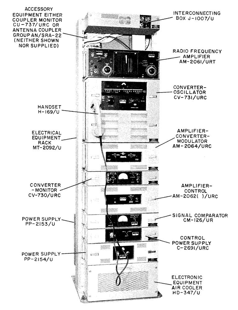
AN/SRC-23
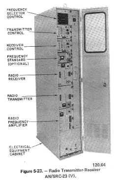
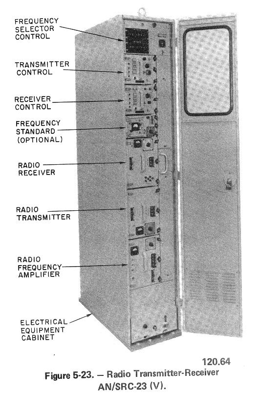
Designed especially for shipboard installations, this transmitter-receiver group may also be used for shore-base installations and consists of eight basic units located within a cabinet.
- The front panel of the transmitter control unit provides the controls for manually selecting the modes of operation for the transmitter and amplifier group.
- The receiver control unit provides controls for operating the receiver.
- The frequency selector control unit provides the selector switches for selecting the desired operating frequency for the transmitter and receiver units.
- The radiofrequency amplifier unit receives the signal from the transmitter and amplifies it to 1,000 watts.
- The frequency standard unit is optional equipment, which may be installed in the cabinet when external frequency standard equipment is not supplied. It provides an unmodulated 100-kHz output frequency used for calibrating the radio transmitter and receiver. In case of power failure, an internal 28 VDC battery in this unit will automatically supply power for two hours.
- The electrical equipment cabinet provides mounting space for all of the functional units and other equipment, such as a heat exchanger and blower for cooling the system, patch terminal strips, thermal alarm indicators, a warning panel, primary power circuit breaker, and interconnection system components.
The equipment is completely transistorized except for the use of two electron tubes. A frequency-synthesizer provides transmitter-receiver frequencies separated at 500 hertz intervals across the band. The AN/SRC-23(V) is a single-channel version of the four-channel service test NTDS (Naval Tactical Data System) AN/SRC-l6
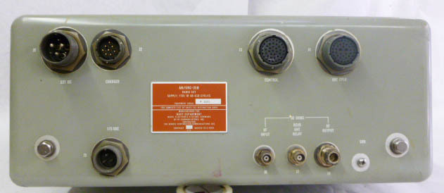
AN/URC-7 transmitter-receiver
USCG
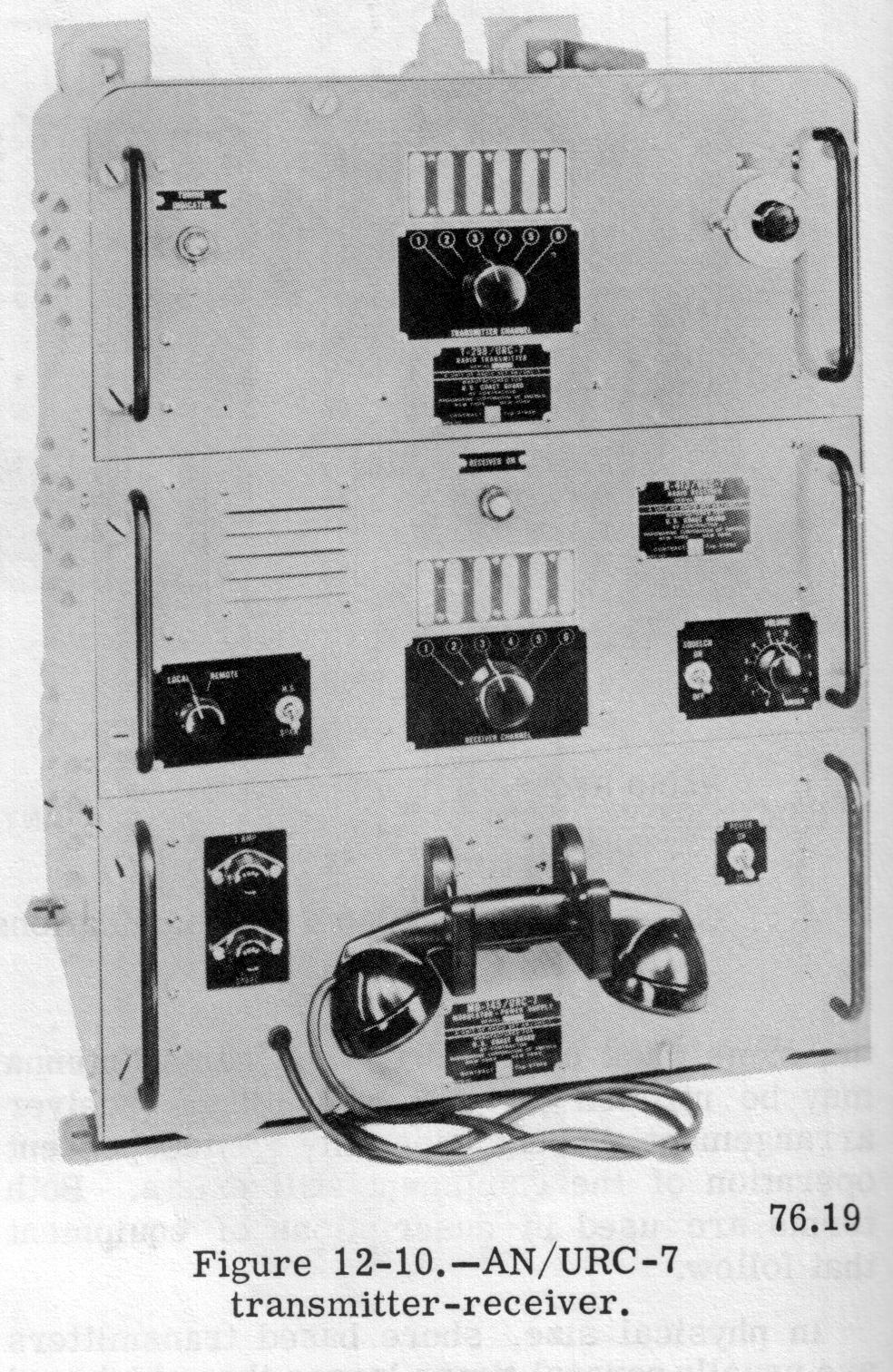
The AN/URC-7 is used principally in service craft and auxiliary-type ships, such as tugs, transports, tankers, and ships of the amphibious force.
AN/URC-8(XN-1)
R-627/URC-8
T-474/URC-8
Transmitter-Receiver
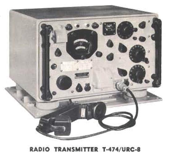
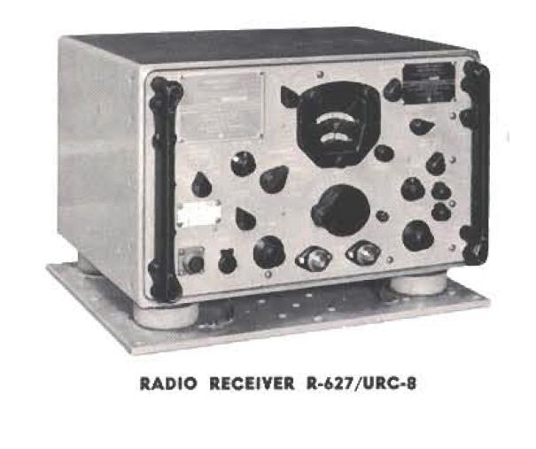
Prototypes only - intended as replacement for TCS
2-20 mc, AM-CW, 42w output
16 present frequencies
PTO or xtal control (4 xtals)
Click here for photos and more info - thanks to K4OZY
AN/URC-8 (XN-2)
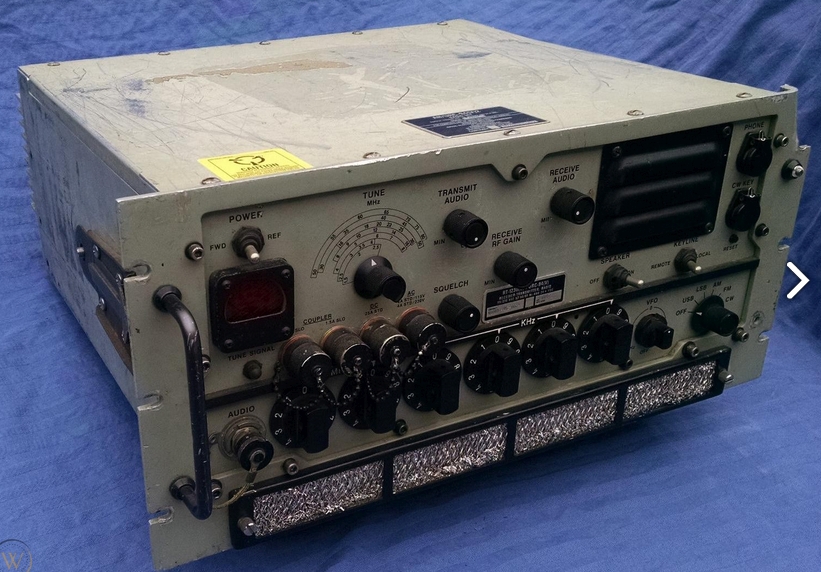
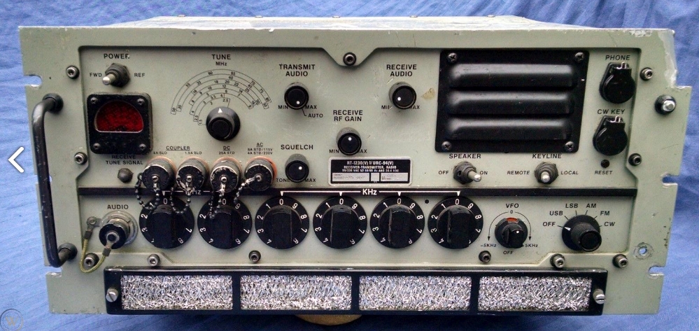
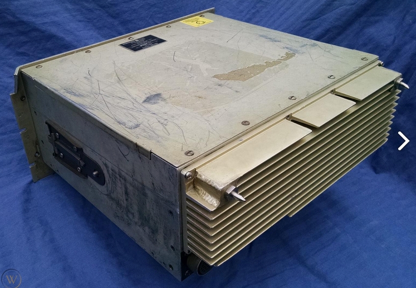
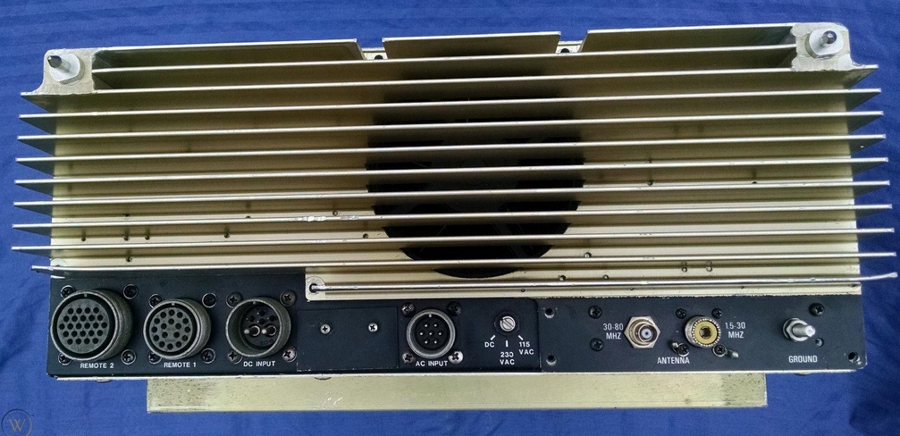
AN/URC-32
AN/URC-32A
AN/URC-32B
Transceiver
HF SSB transceiver
2-30mc, CW/SSB, 500w
Collins KWT-6 family
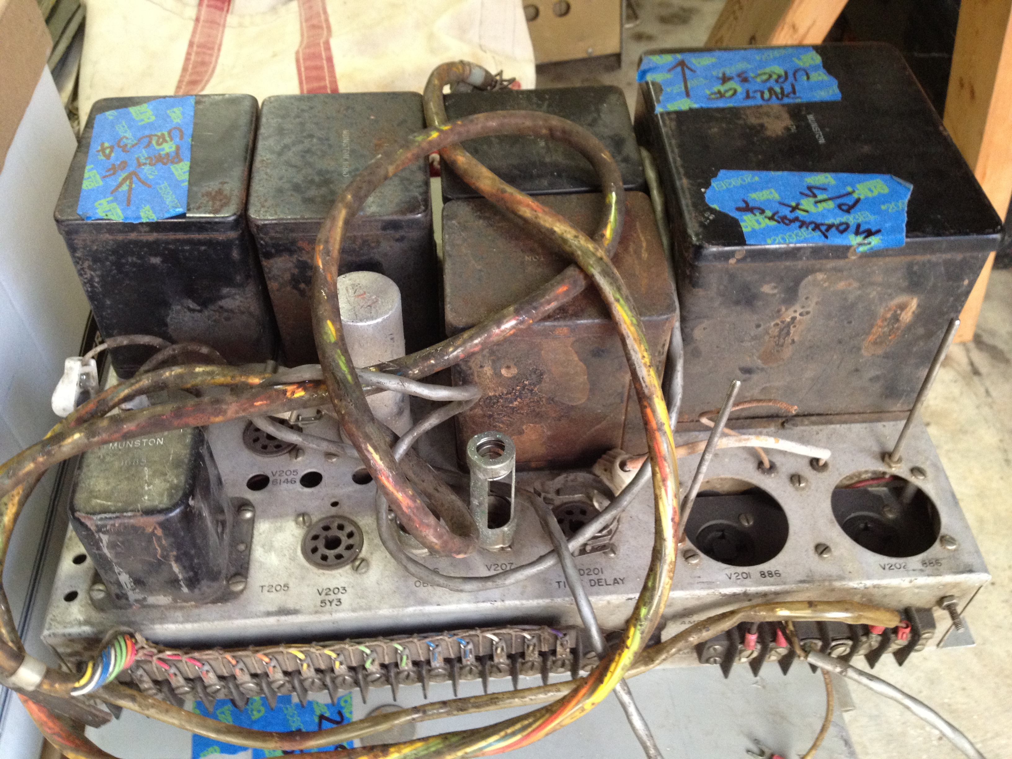
AN/URC-34 (115vac)
AN/URC-34X (115vdc)
USCG only?

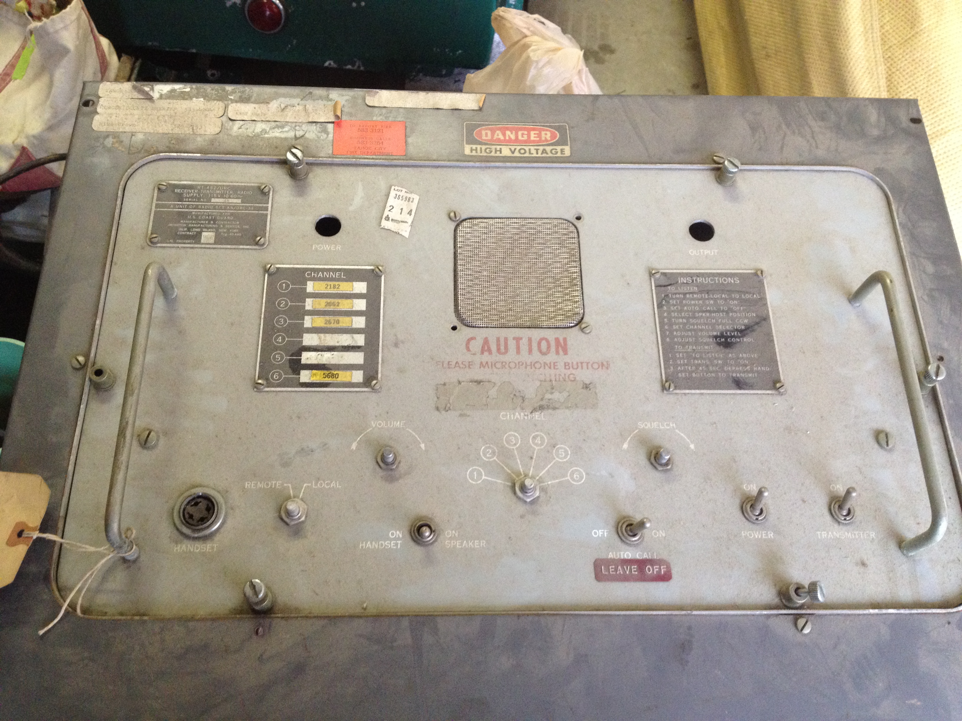
RT-452/URC Transmitter-Receiver

RT-452/URC Transmitter-Receiver
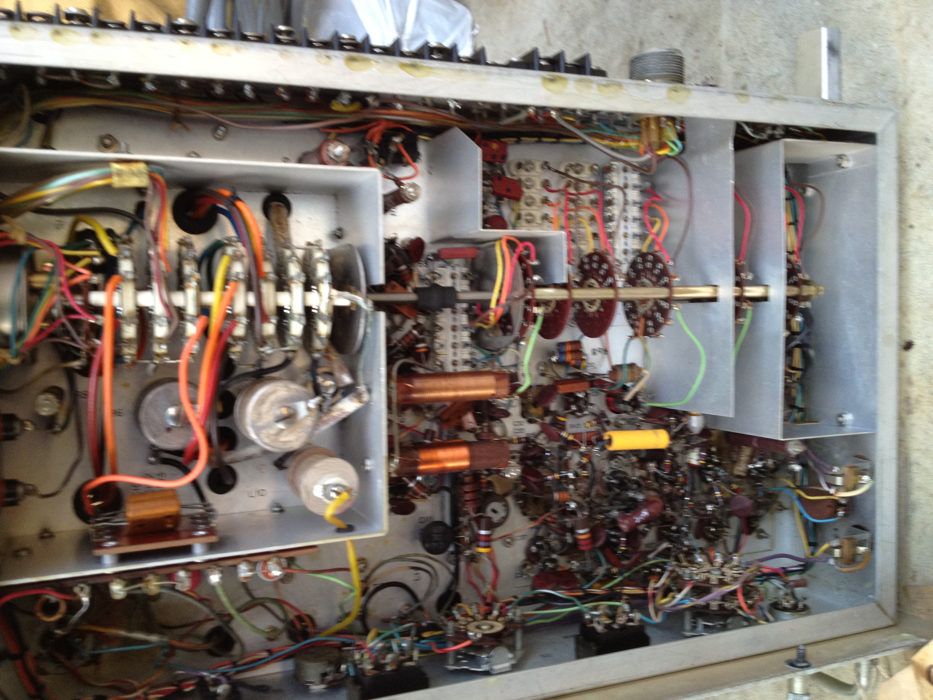
C-2521/URC remote control
MD-336/URC-34 modulator & p/s
(MD-337 for AN/URC-34X)
Manual NAVSHIPS 93349

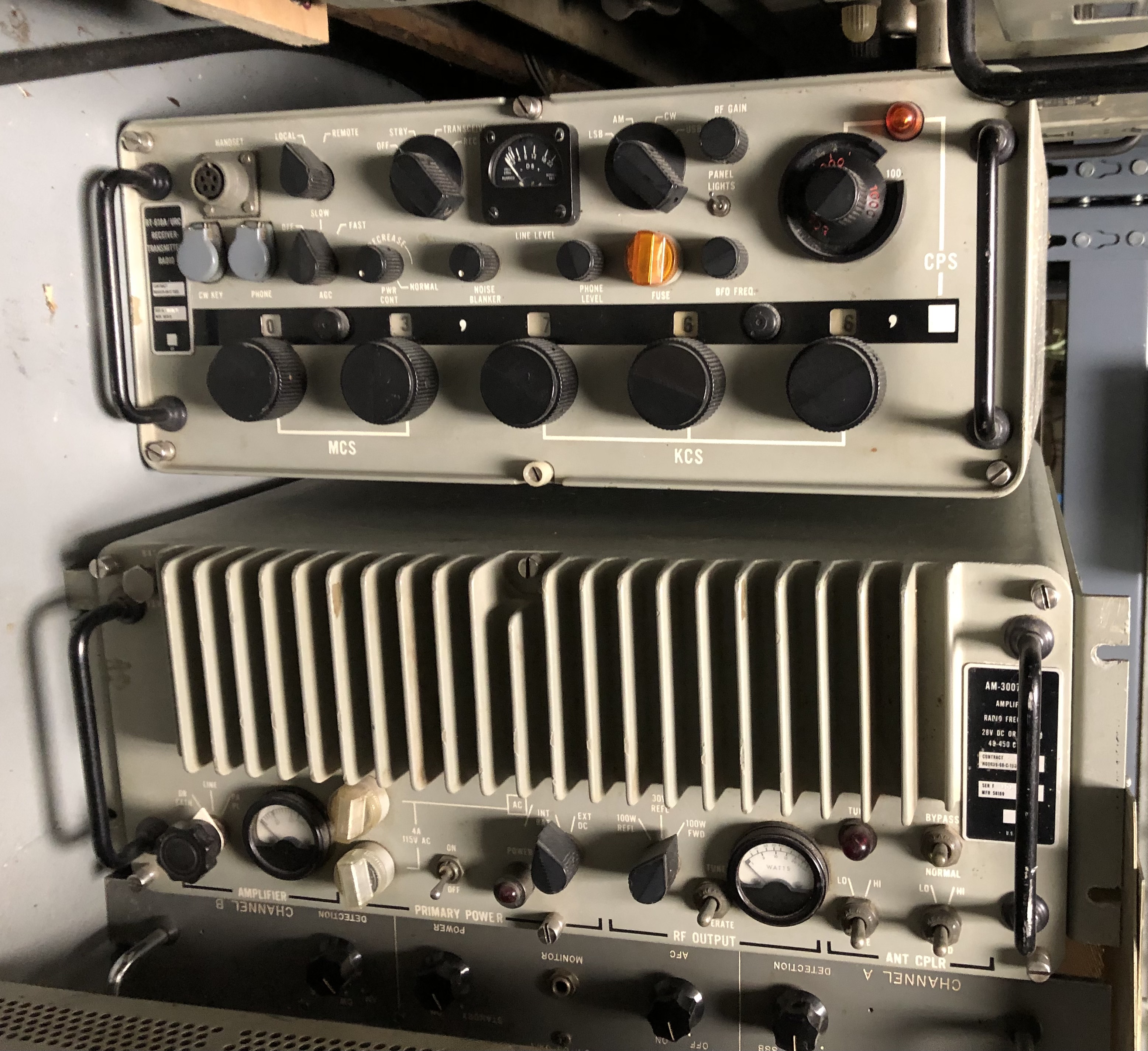
AN/URC-35 Transceiver
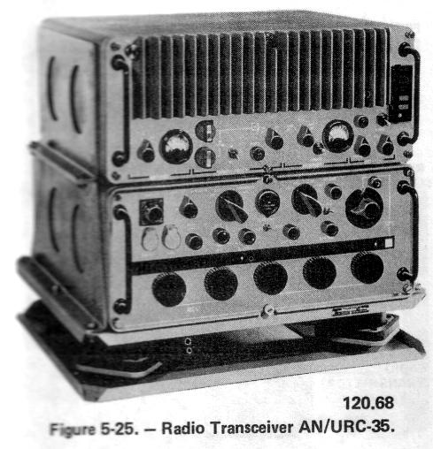
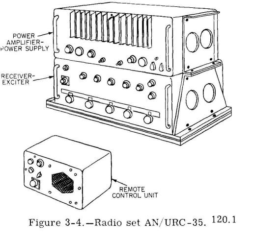
2-30 mc, 100w

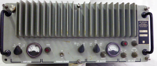
AM-3007/URC amplifier
C-9044/URC-35 remote control
used with CU-937/UR antenna coupler
1967 Introduction
predecessor - General Dynamics SC-series

C-9044/URC-35 remote control


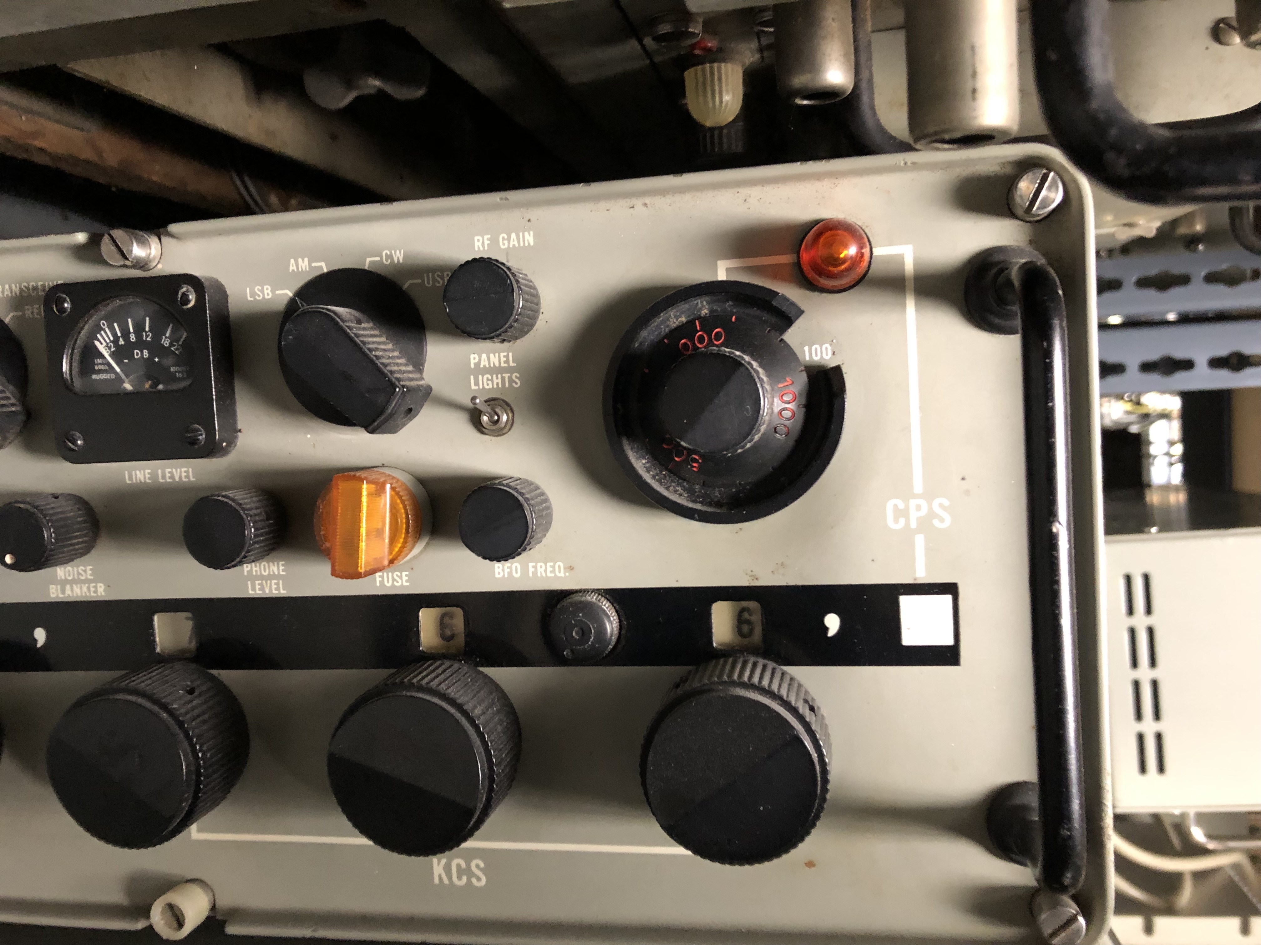
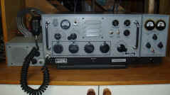
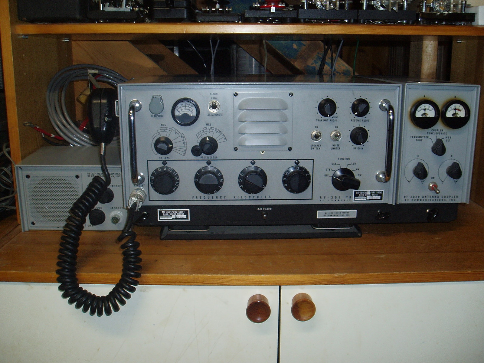
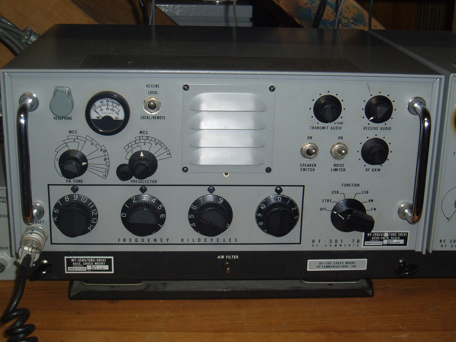
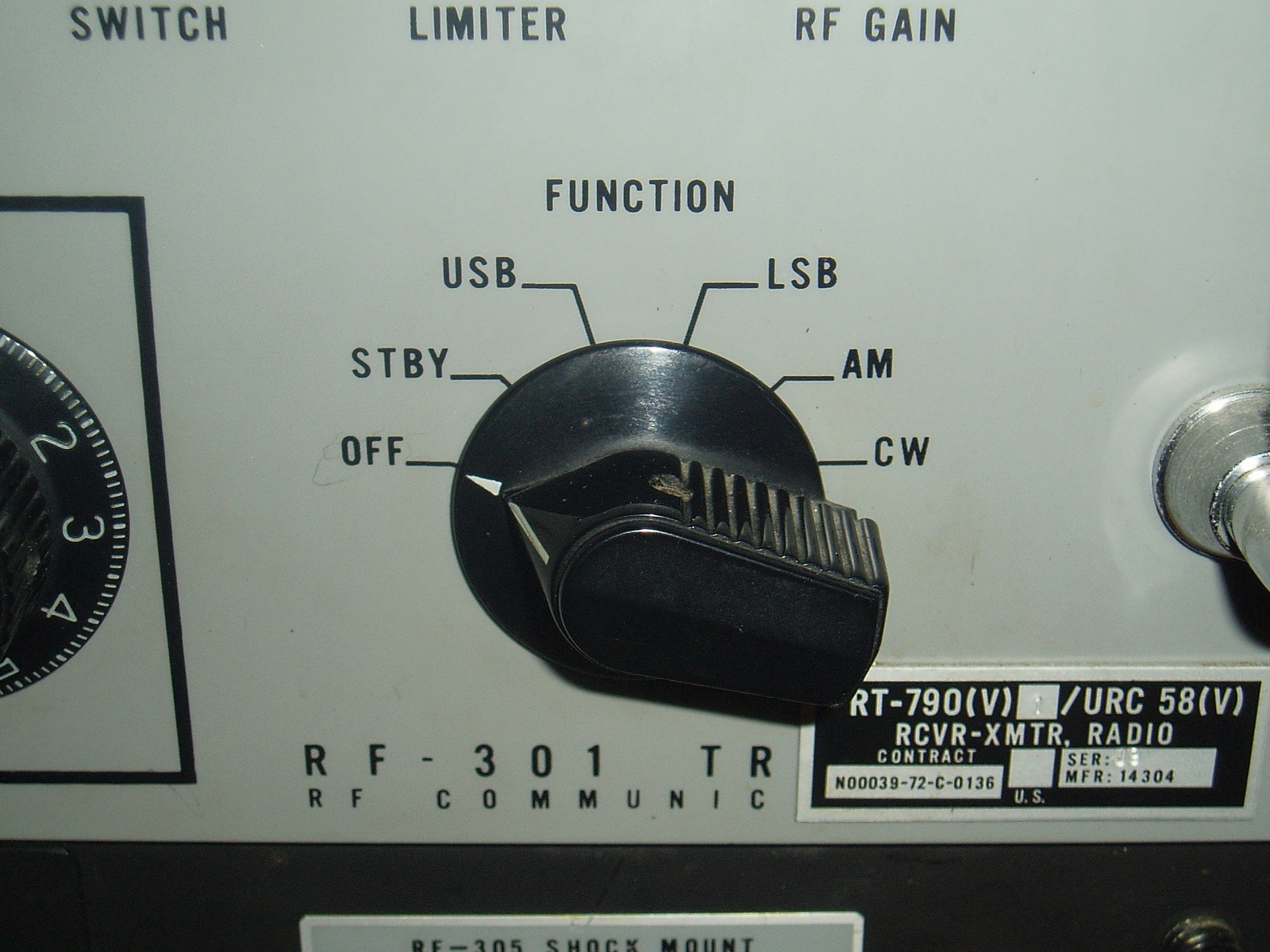
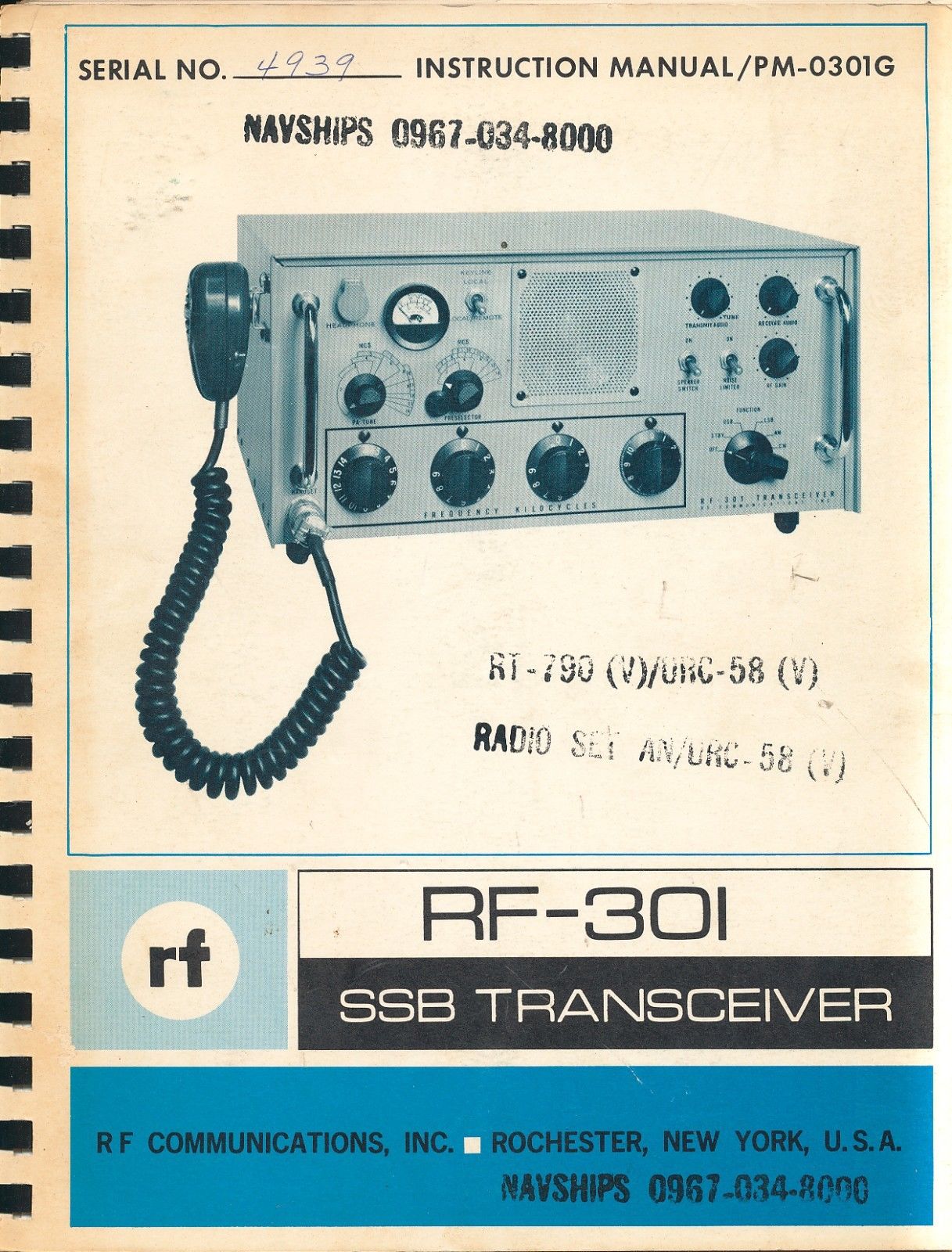
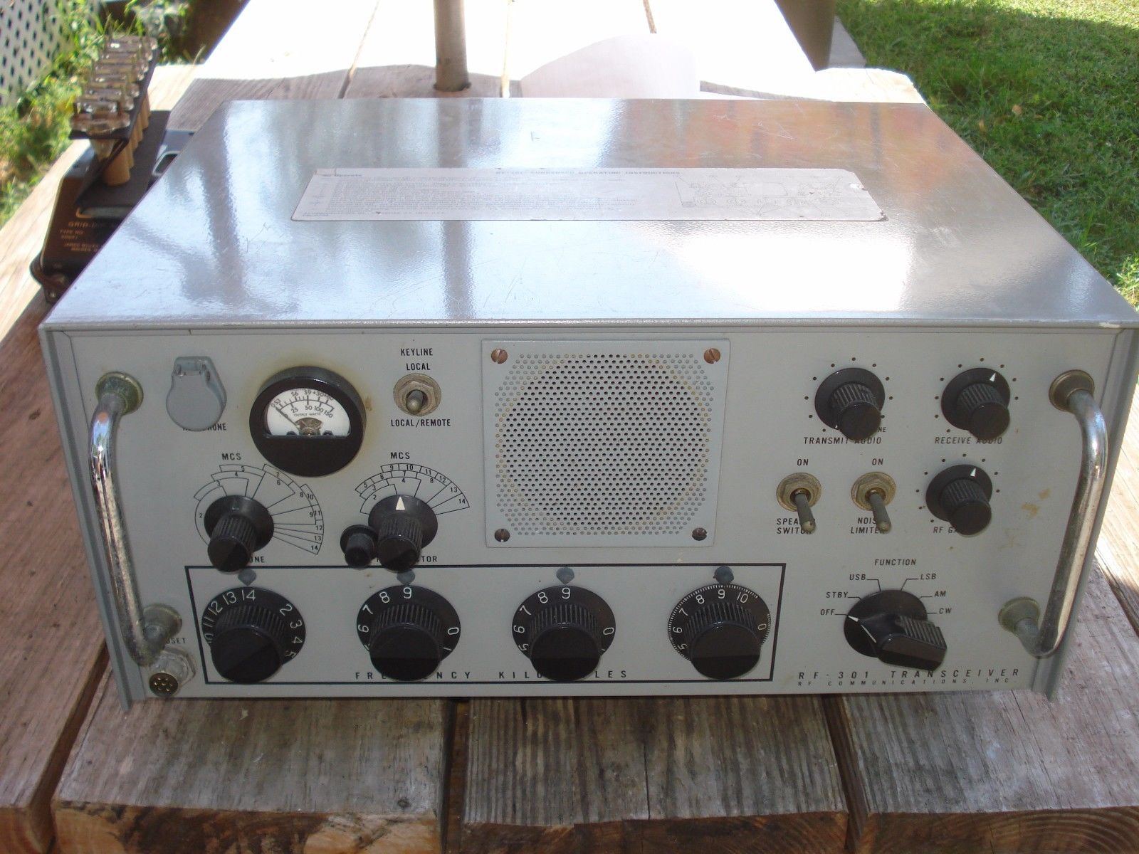
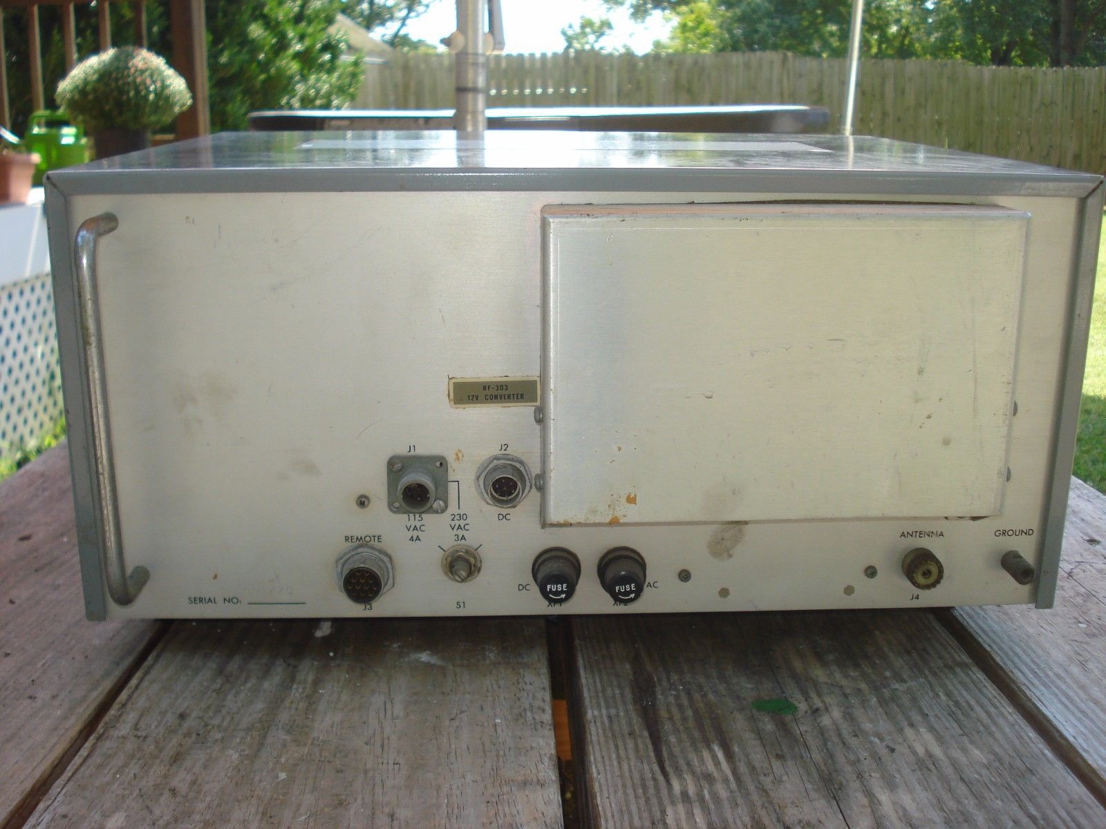
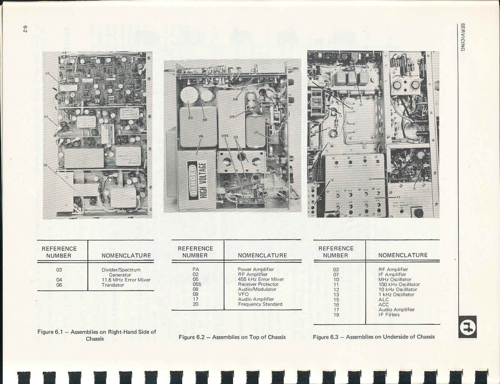
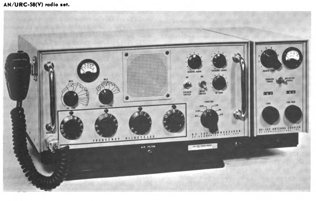
AN/URC-58(V)
(RF Communications RF-301)
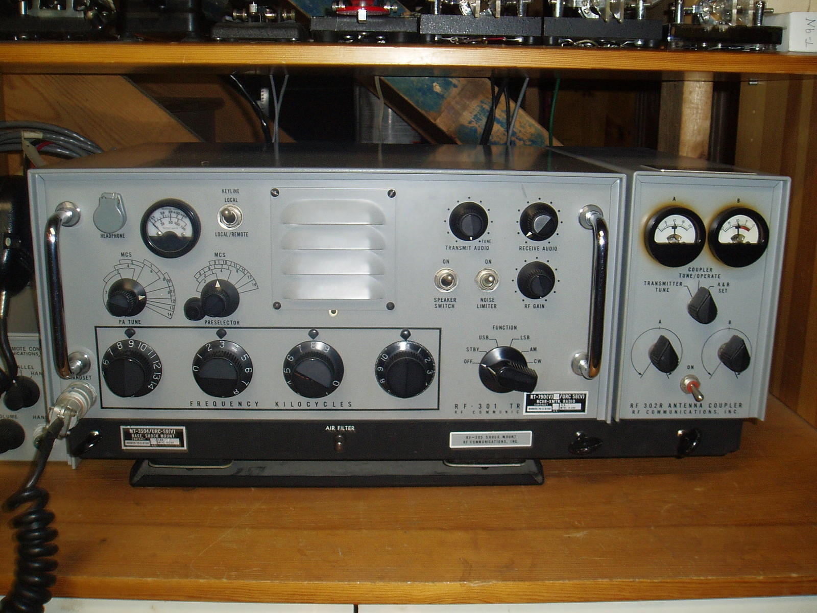
Download manual
(NAVSHIPS 0967-034-8000_
RT-790/URC-58 Rcvr-Xmtr
MT-3504/URC-58 mount
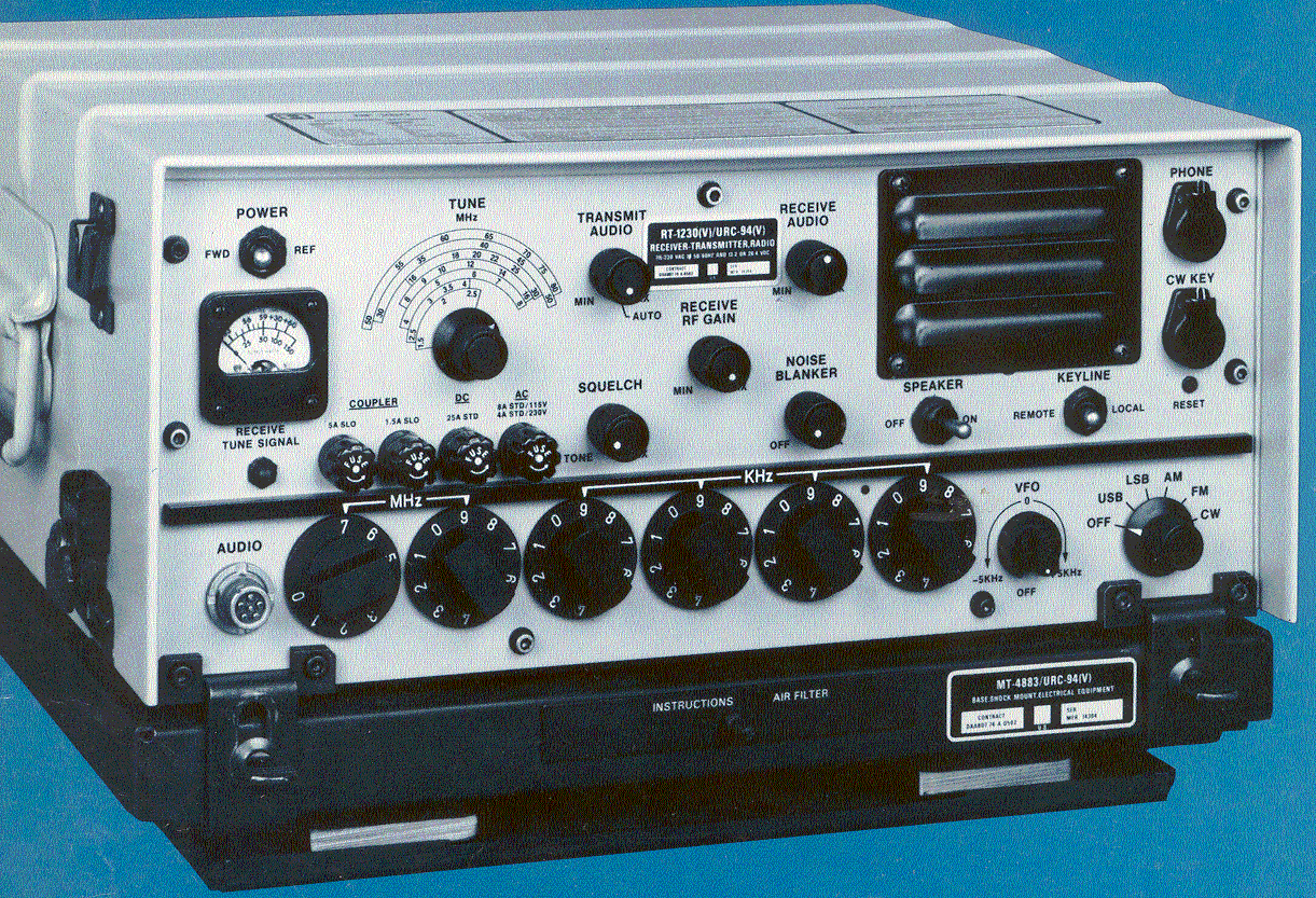
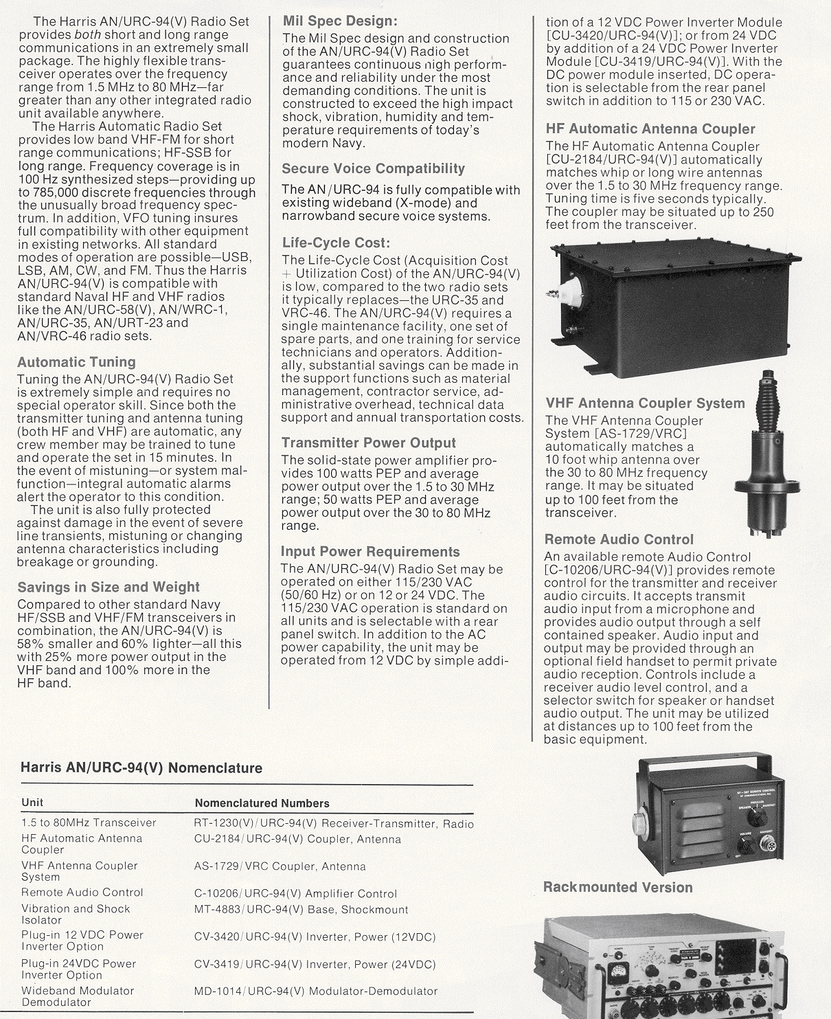
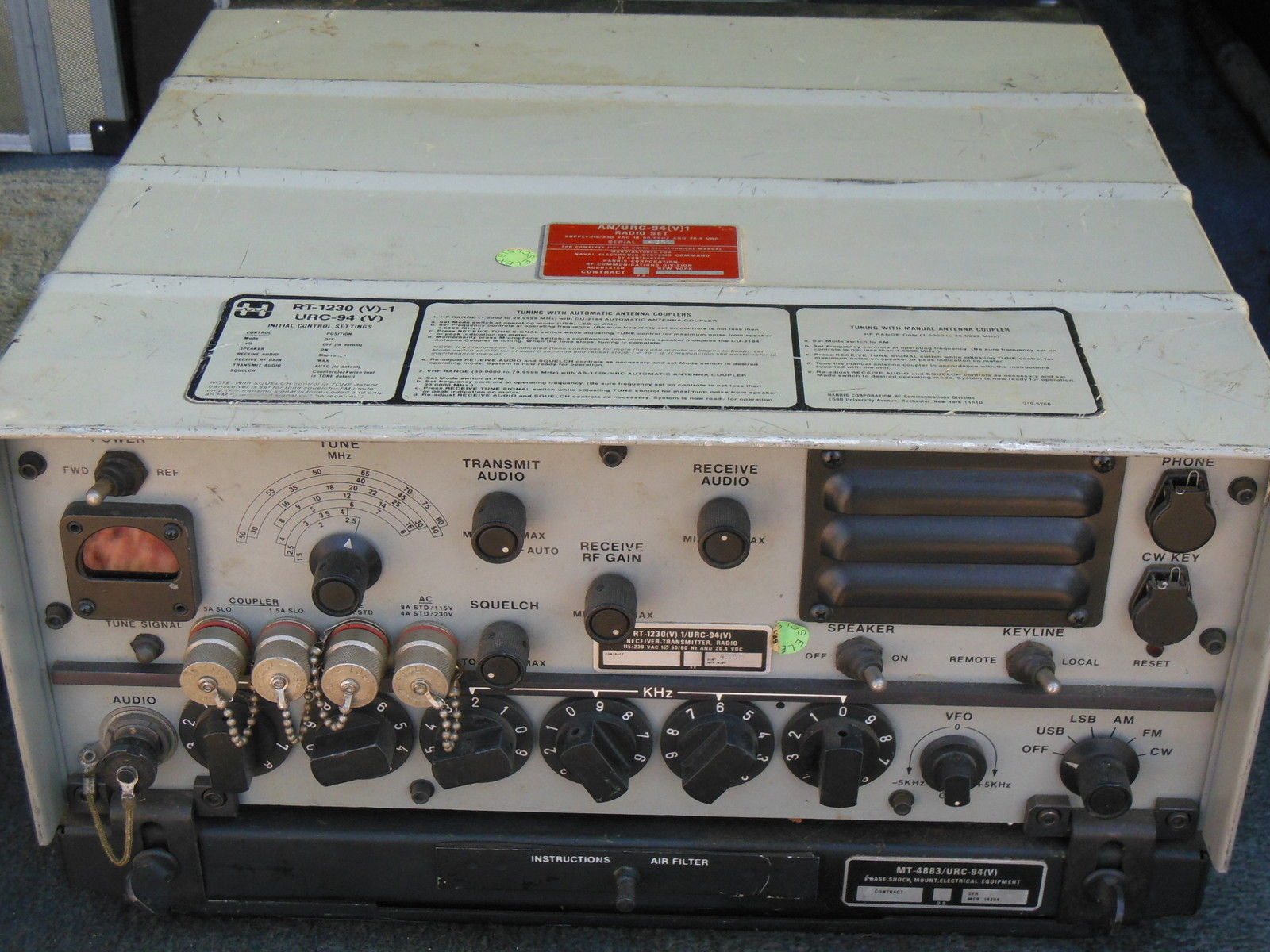
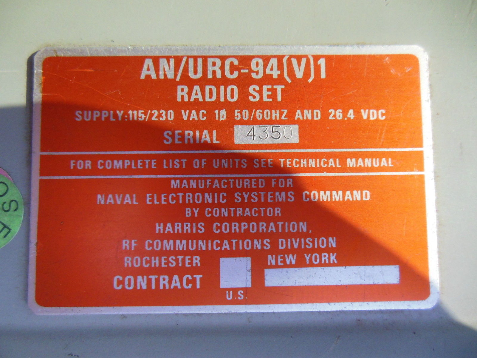
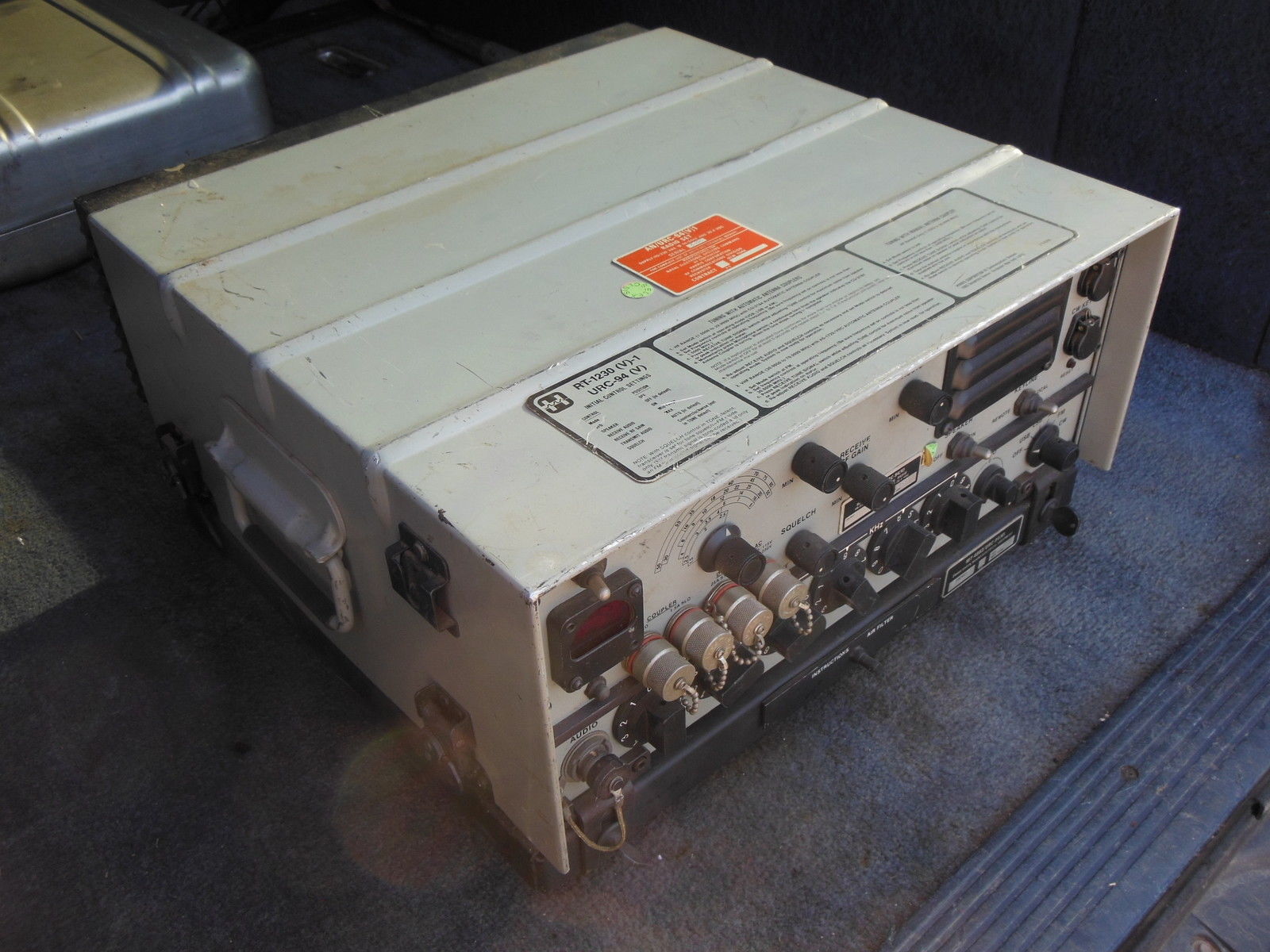
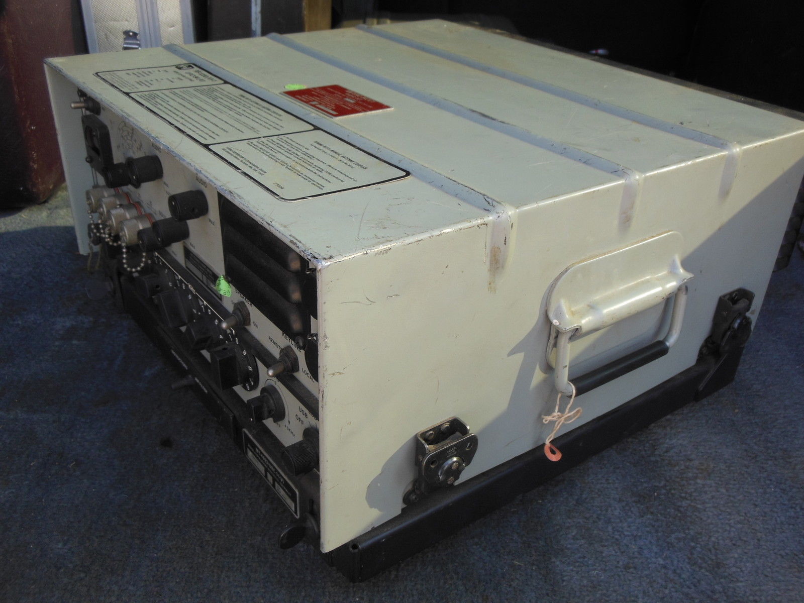
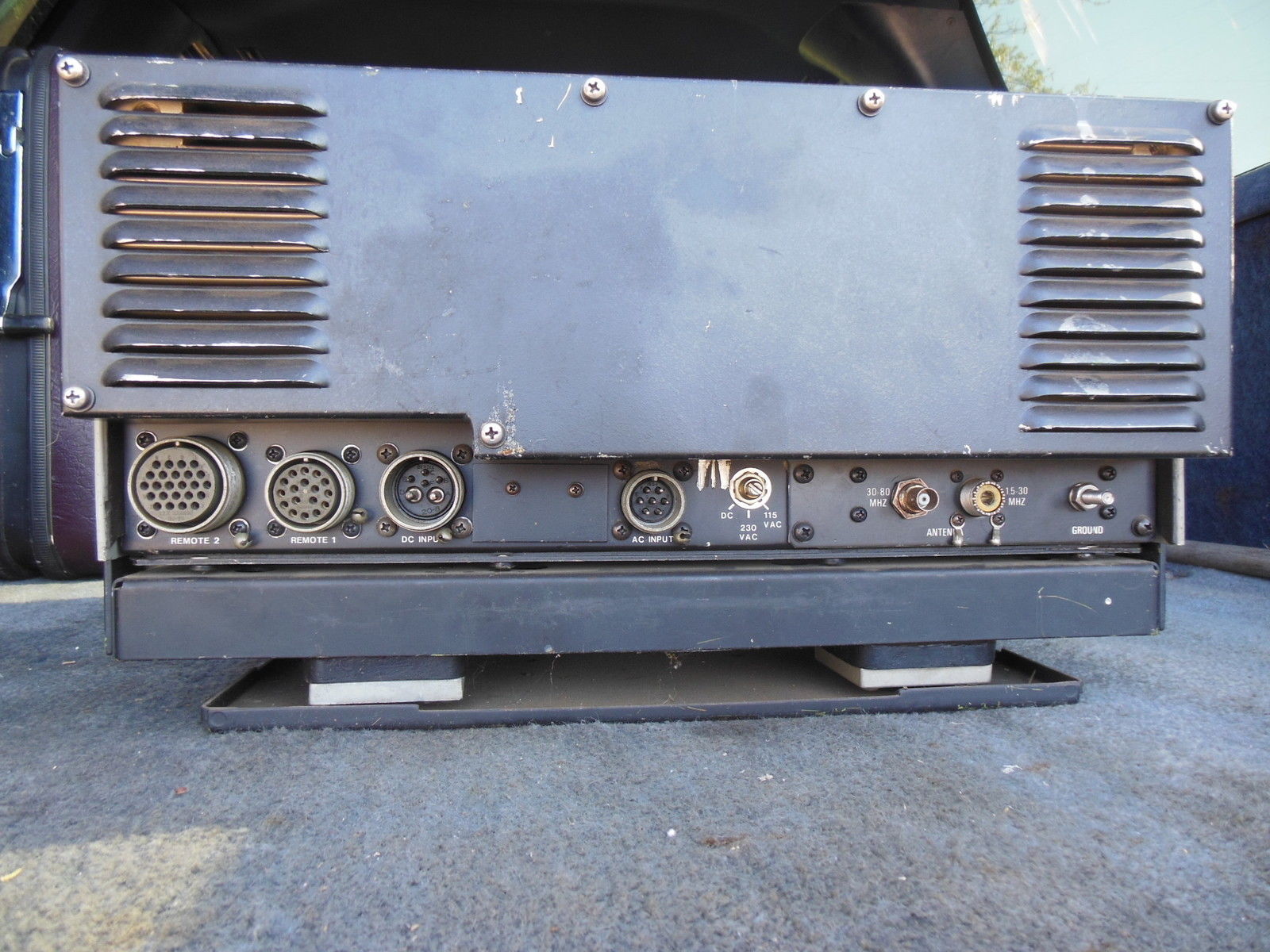
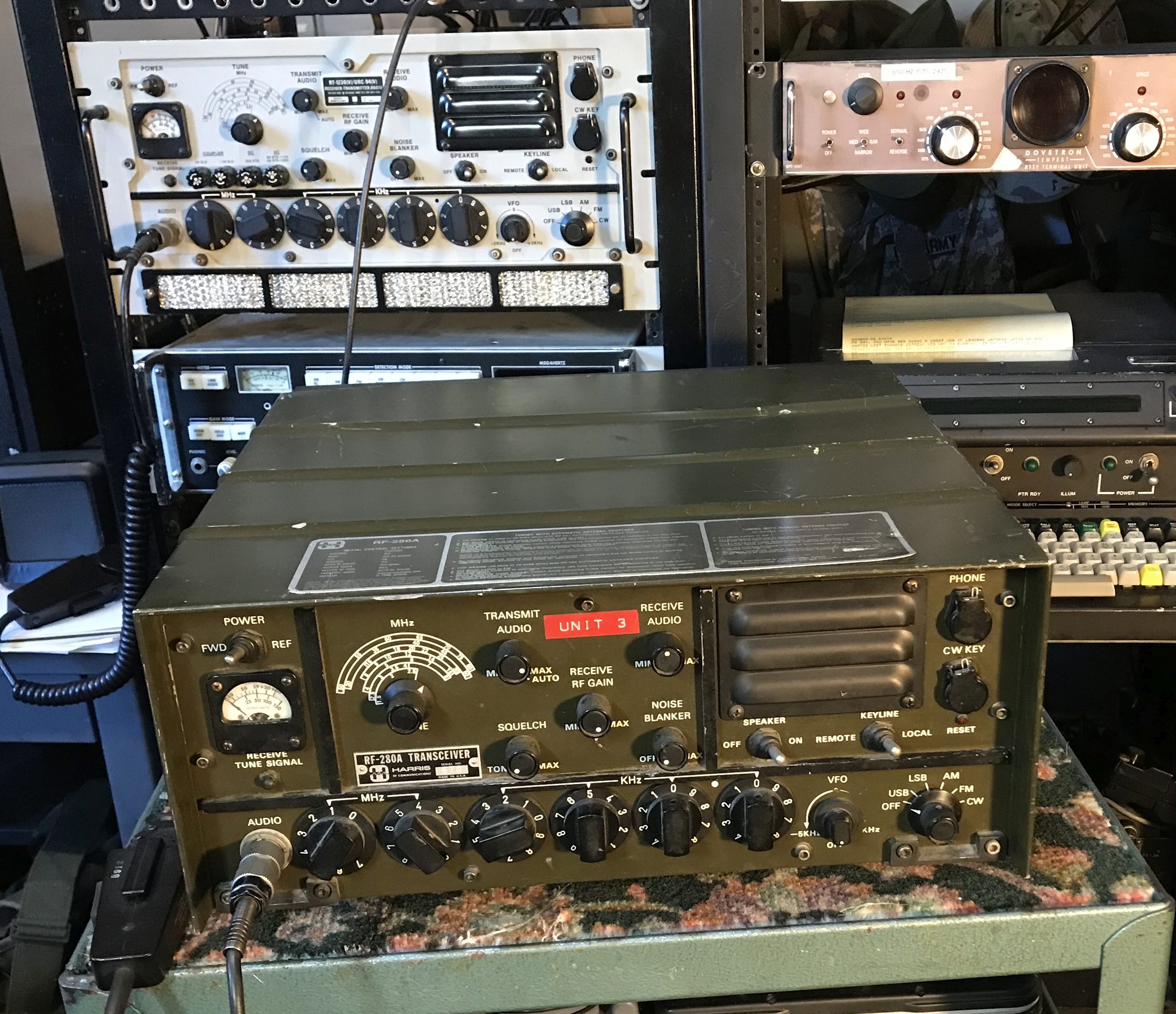
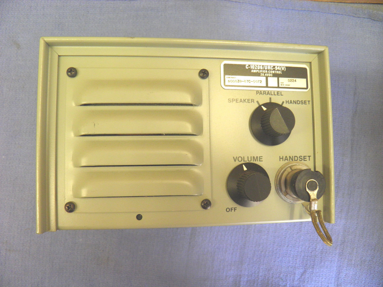
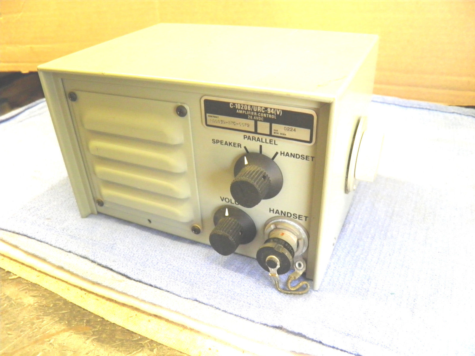
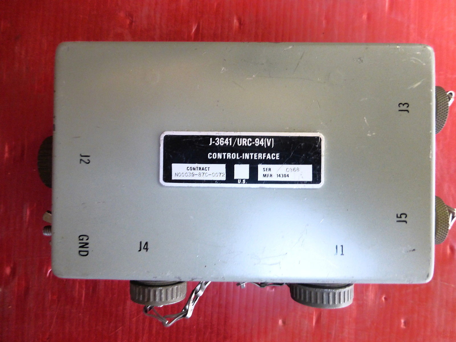
AN/URC-94(V)
(Harris RF-280)
(V) 1 shock mount
(V) 2 rack mount
- thanks to KA3EKH
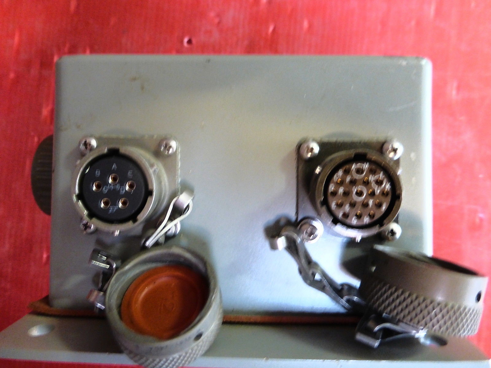
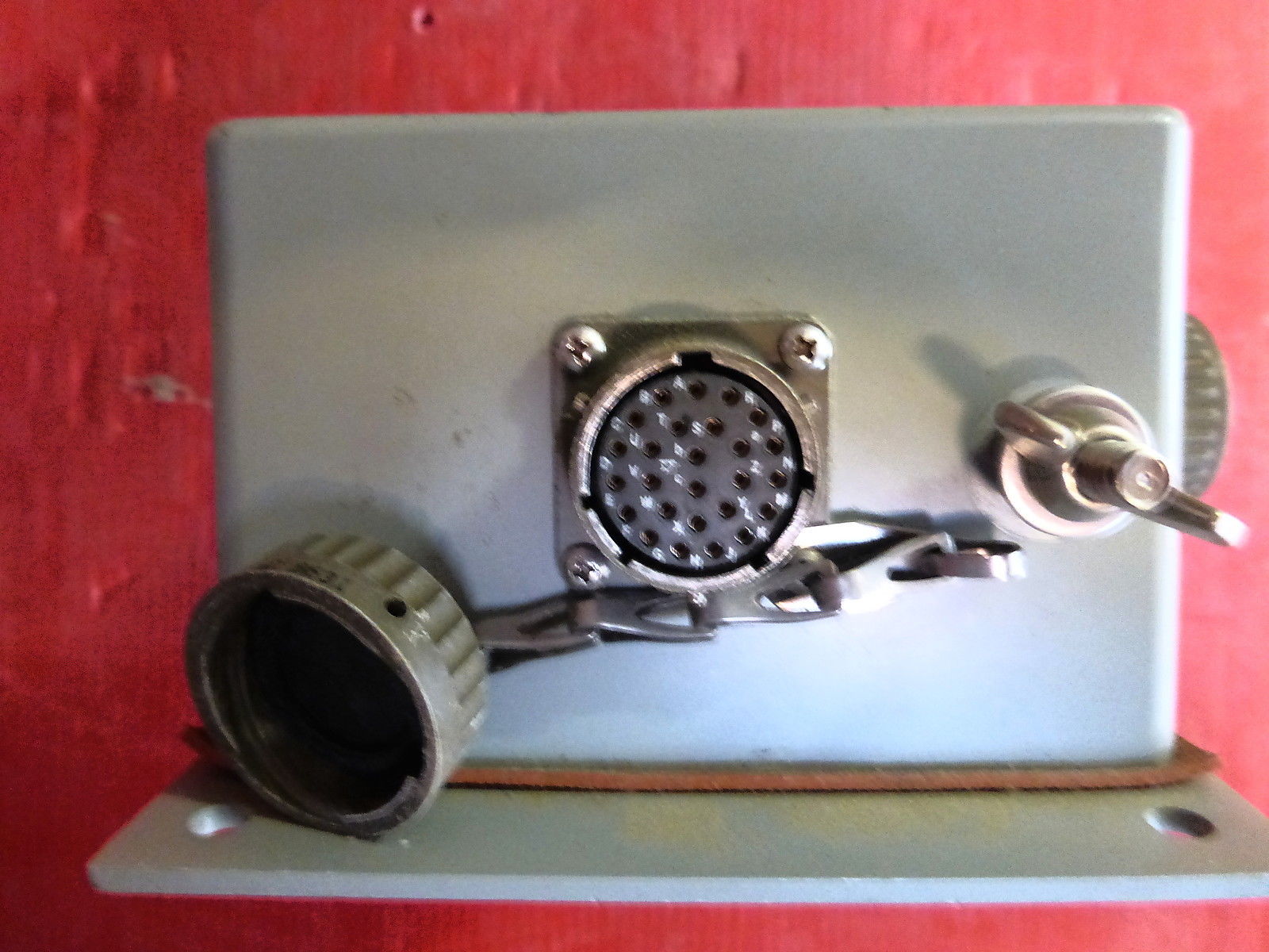
AN/URC-119(V)
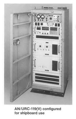
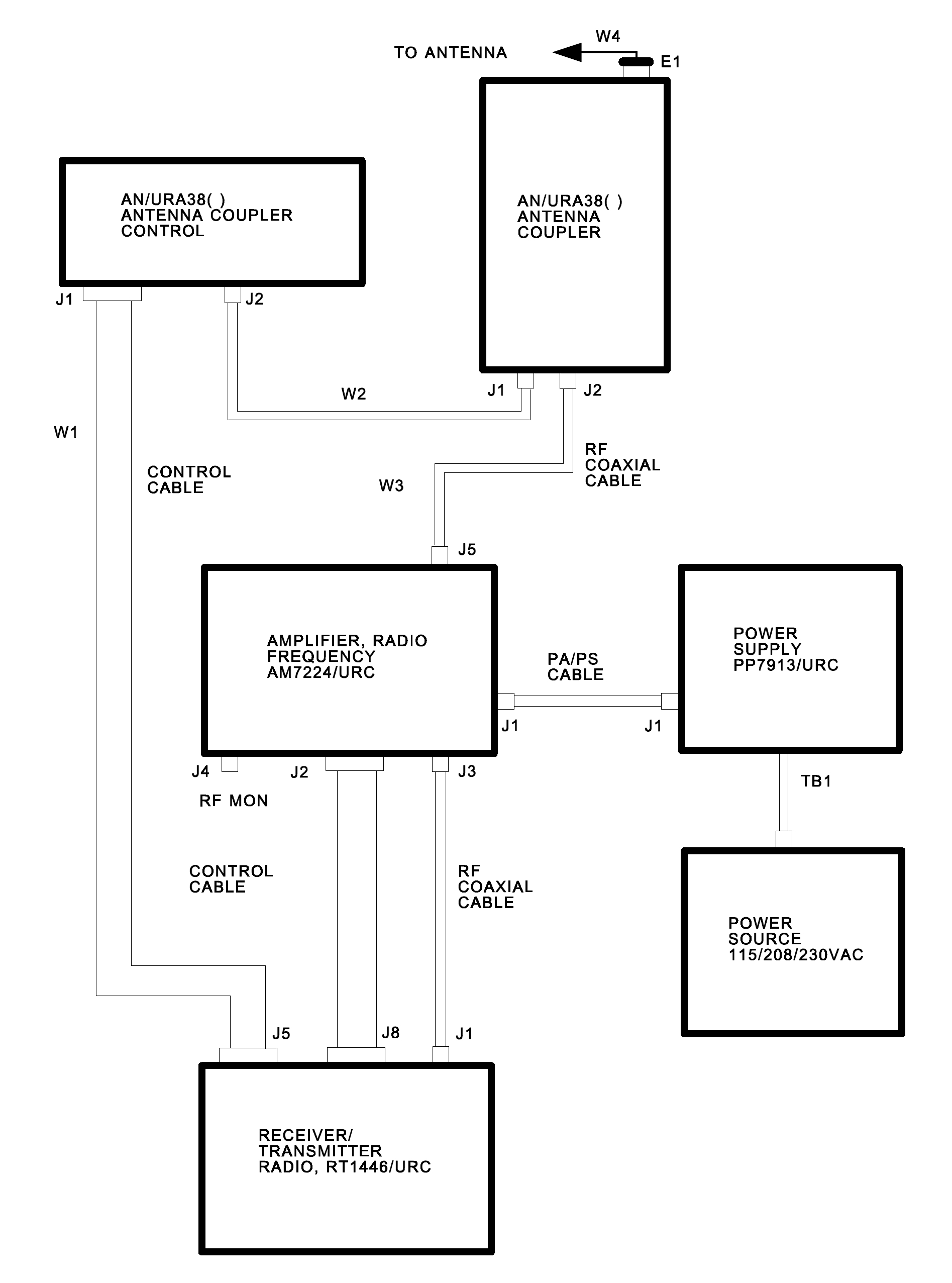
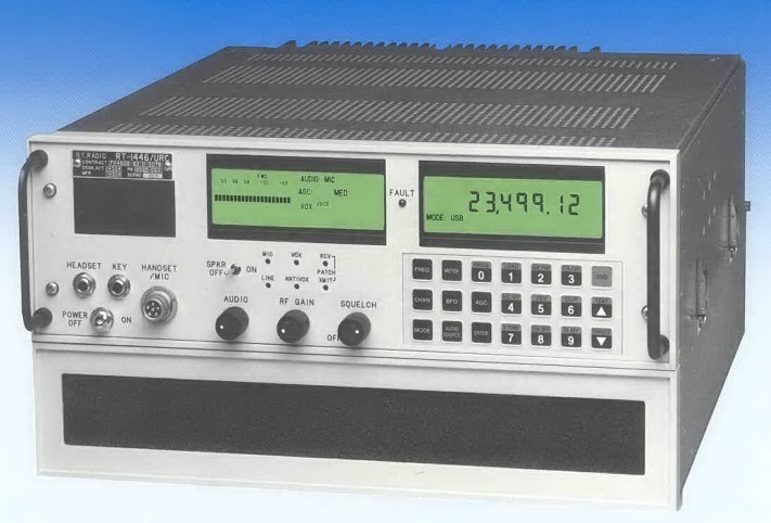
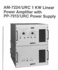
AM-7224/URC 1 kw linear amp
PP-7913/URC power supply
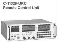
C-11329/URC remote control
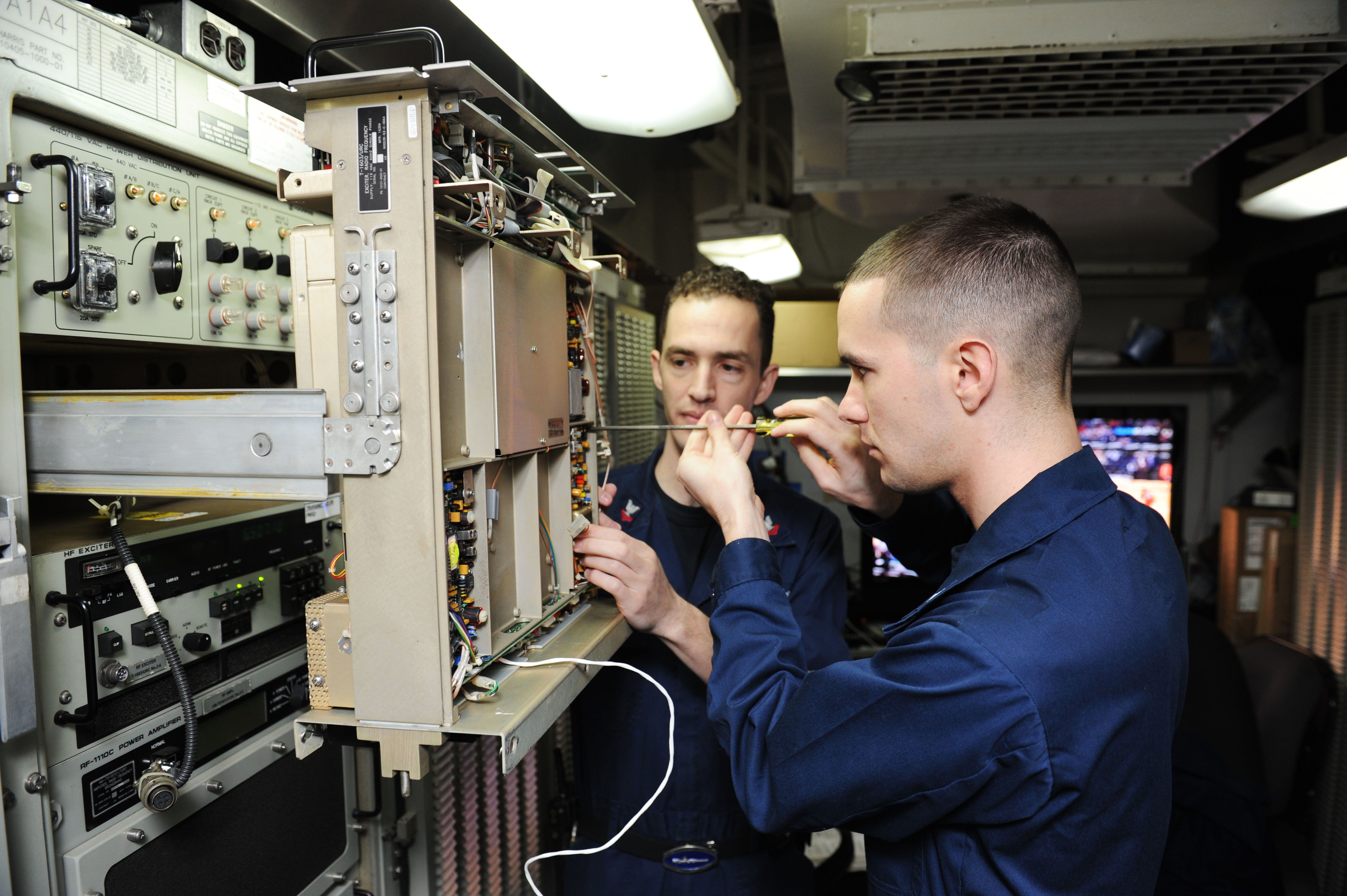
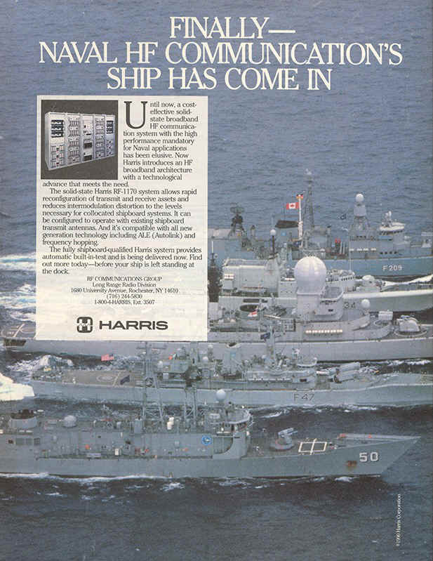
AN/URC-131(V)
Harris
HFRG Transceiver
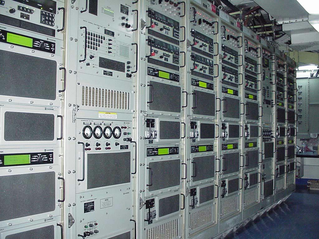

Transmit Subsystem: The Transmit Subsystem operates (in increments of 10 Hz) in the frequency range of 2 Mhz to 30 Mhz and is used primarily for broadband circuits. The Transmit subsystem is designed to allow all exciters to operate in the Link 11 mode, but contains the assets required to support two (2) 1kW narrowband circuits which are the primary HF Link 11 circuits. The operational capabilities of the transmit subsystem require both broadband and narrowband antennas. The operational configuration of the transmit subsystem is accomplished in response to commands from the CMS and frequency changes (except narrowband) are completed in less than 100 milliseconds. The transmit subsystem reports to the CMS when the system is configured and also reports detected failures.
Receive Subsystem: The Receive Subsystem operates (in increments of 10 Hz) in the frequency range of 14 Khz to 1.619 Mhz and 2 Mhz to 30 Mhz. The receive subsystem requires at least two broadband antennas and 1 or 2 additional antennas dedicated to the use of the Ship Signal Exploitation Equipment (SSEE). The operational configuration of the receive subsystem is accomplished in response to commands from the CMS and frequency changes are completed in less than 20 milliseconds. The receive subsystem reports to the CMS when the system is configured and also reports detected failures.
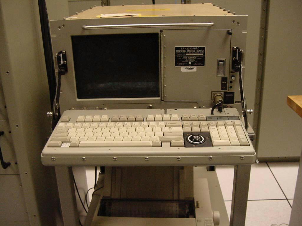
Control/Monitor Subsystem (CMS) The Control/Monitor Subsystem is the backup point of control for the HFRG when the system is being controlled by the Surface Ship Automated Communications Control System (SSACCS) (part of the Communications Support System (CSS)). The SSACCS normally controls the HFRG through an interface with the CMS, but if the SSACCS becomes inoperable the CMS automatically assumes the functions of remote control, performance monitoring, test, operator interface, and display of the operational characteristics. The CMS is used to send configuration commands to the transmit and receive subsystems and, in turn, receive configuration completion and operational characteristics from these subsystems.
From "Jane's Military Communications"- The AN/ URC-131(V) High Frequency Radio Group (HFRG) system is an integrated, solid-state naval communications suite, designed to provide a balance between transmitter and receiver performance in a co-located shipboard environment. The three main communications components of the AN/URC-131 (V) are the Broadband Transmit Group (BTG), the Narrowband Transmit Group (NTG) and the receive system. The third-generation BTG is of solid-state design and provides coverage of the 2 to 30 MHz band. Three BTG variants have been produced - a 4 kW (8 circuit) system, an 8 kW (17 circuit) system and a 12 kW (26 circuit) system. All three systems use only two topside broadband antennas. The NTG consists of up to three solid-state 1 kW transmitters with power post-selectors and digital antenna couplers. The NTG can be tuned in the presence of adjacent antenna interference and offers completely silent tuning. It has a rapid-tune digital antenna coupler. It can also serve as a stand-alone system aboard small ship platforms. The receive system's R- 2557A/URC receiver operates over the full LF, MF and HF frequency range from 10 kHz to 30 MHz. Other features include: up to 49 receive circuits; passive antennas, which require no electronics topside; and an atmospheric noise-limited design. The HFRG's HFRG Remote Control/ Monitor Subsystem (RCMS) is designed for 'lights out' operation in the transmitter and receiver compartments. Its features include: a ruggedized, PC workstation with full ASCII keyboard and pointer for function selection/ activation; redundant control buses and subsystem controllers for system survivability.
AN/USC-61(V)
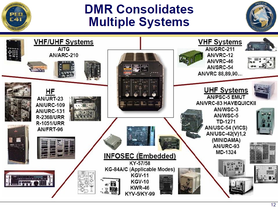
Digital Modular Radio (DMR)
2MHz-2GHz SDR
General Dynamics
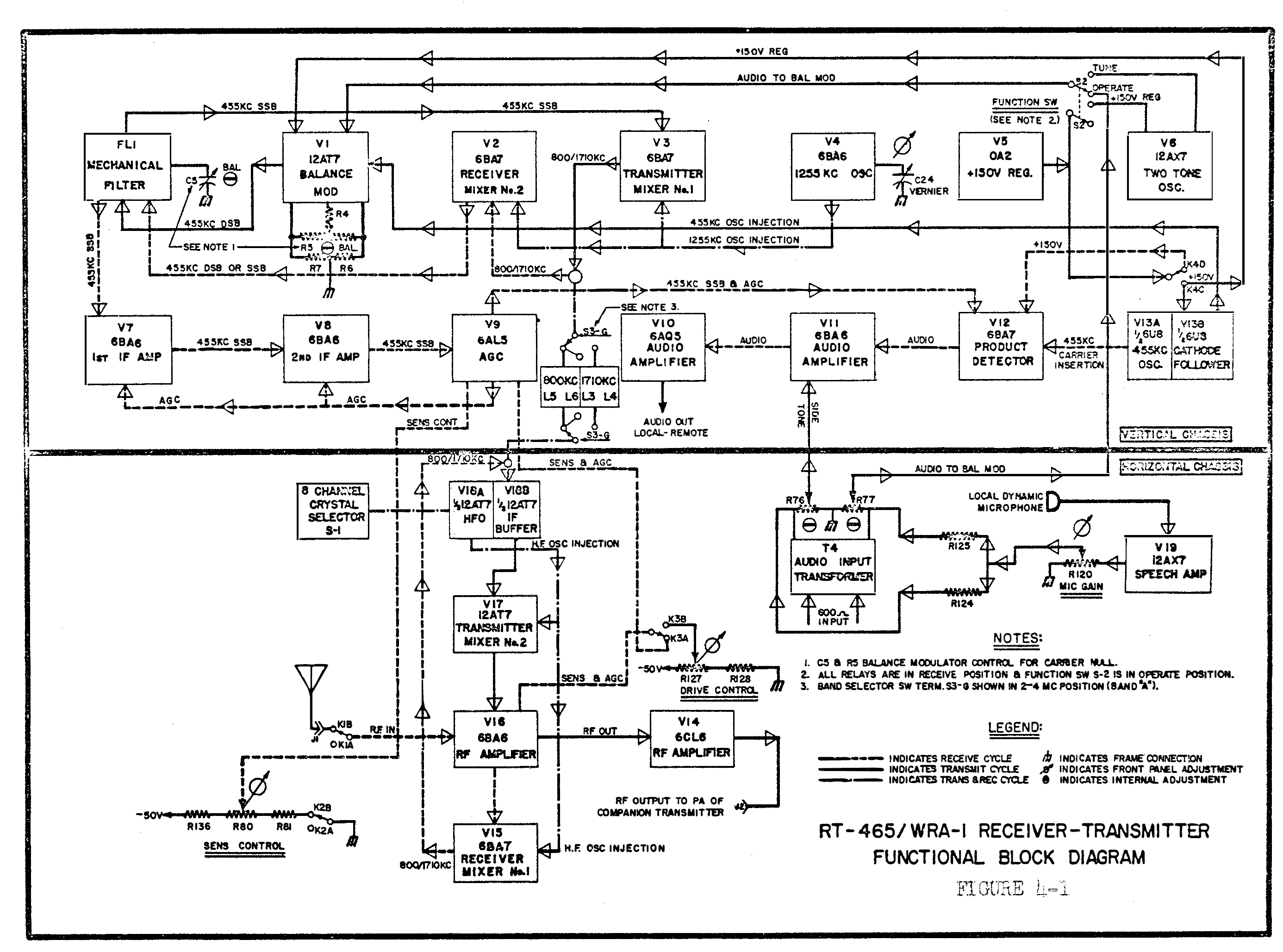
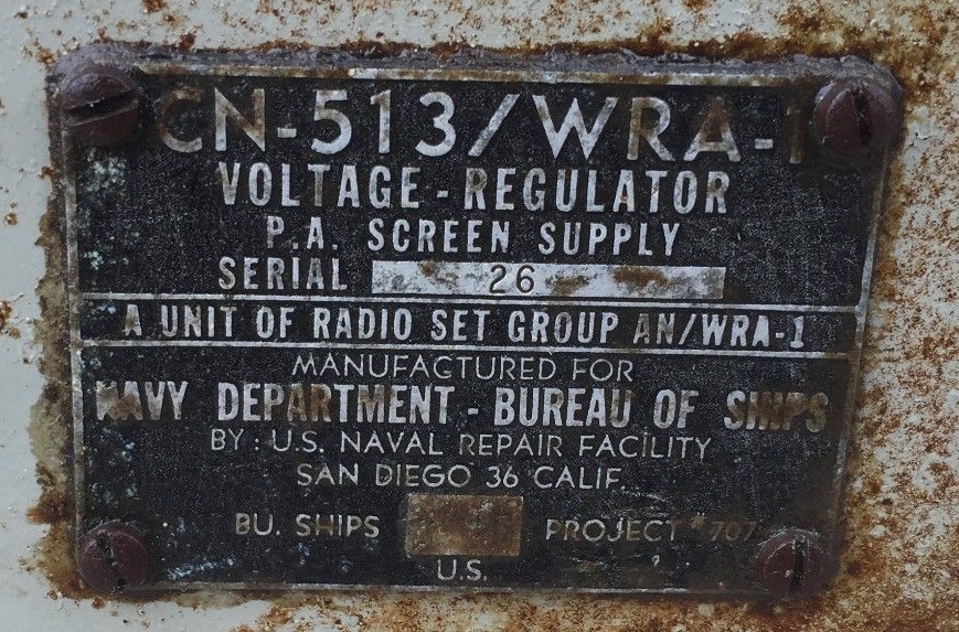
AN/WRA-1 SSB Transceiver
RT-645/WRA-1 SSB Transceiver
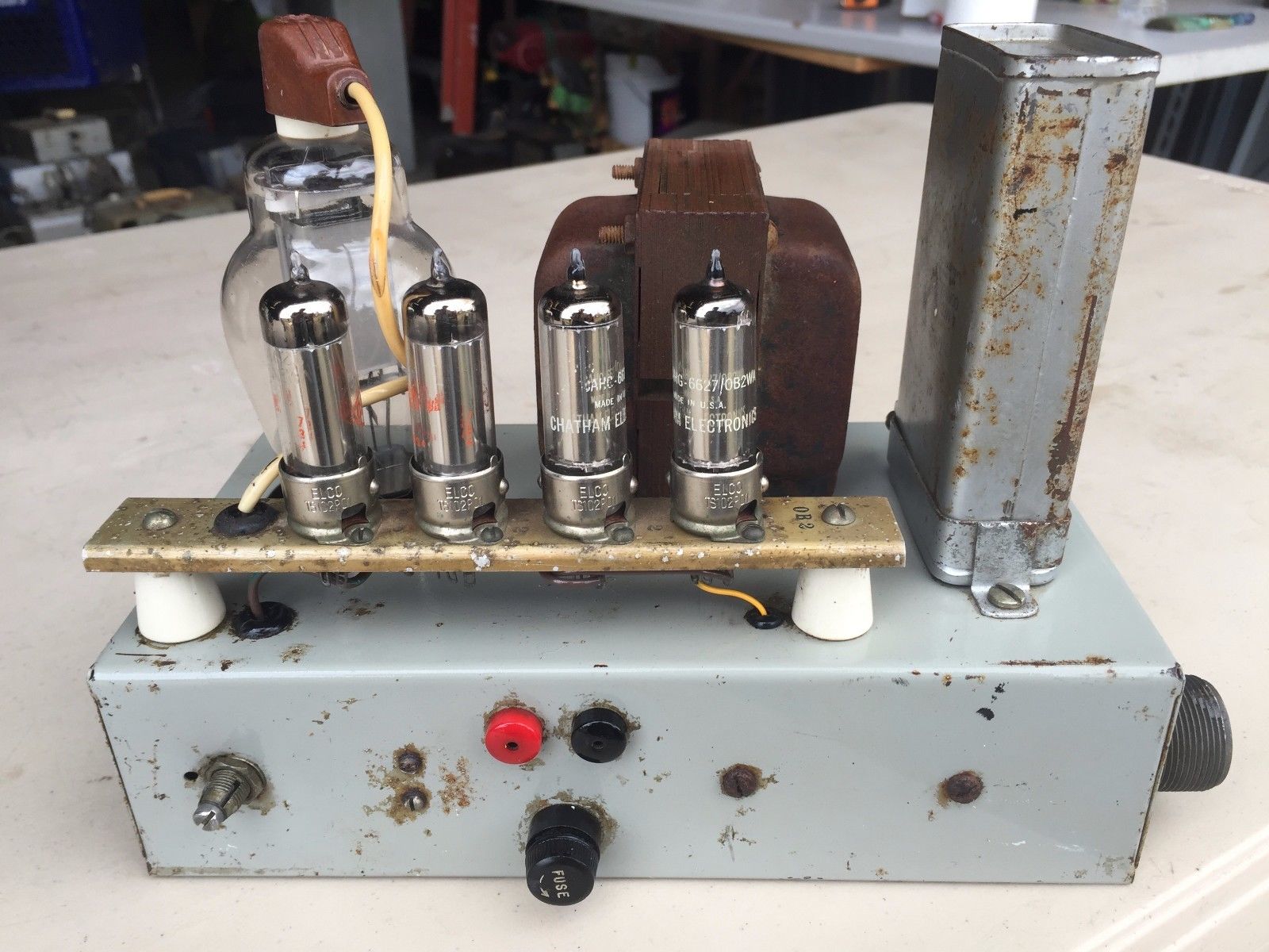
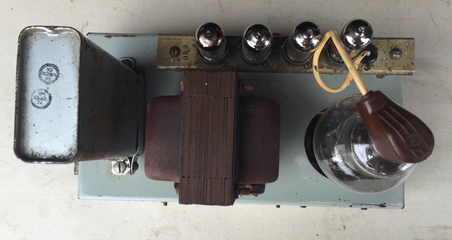
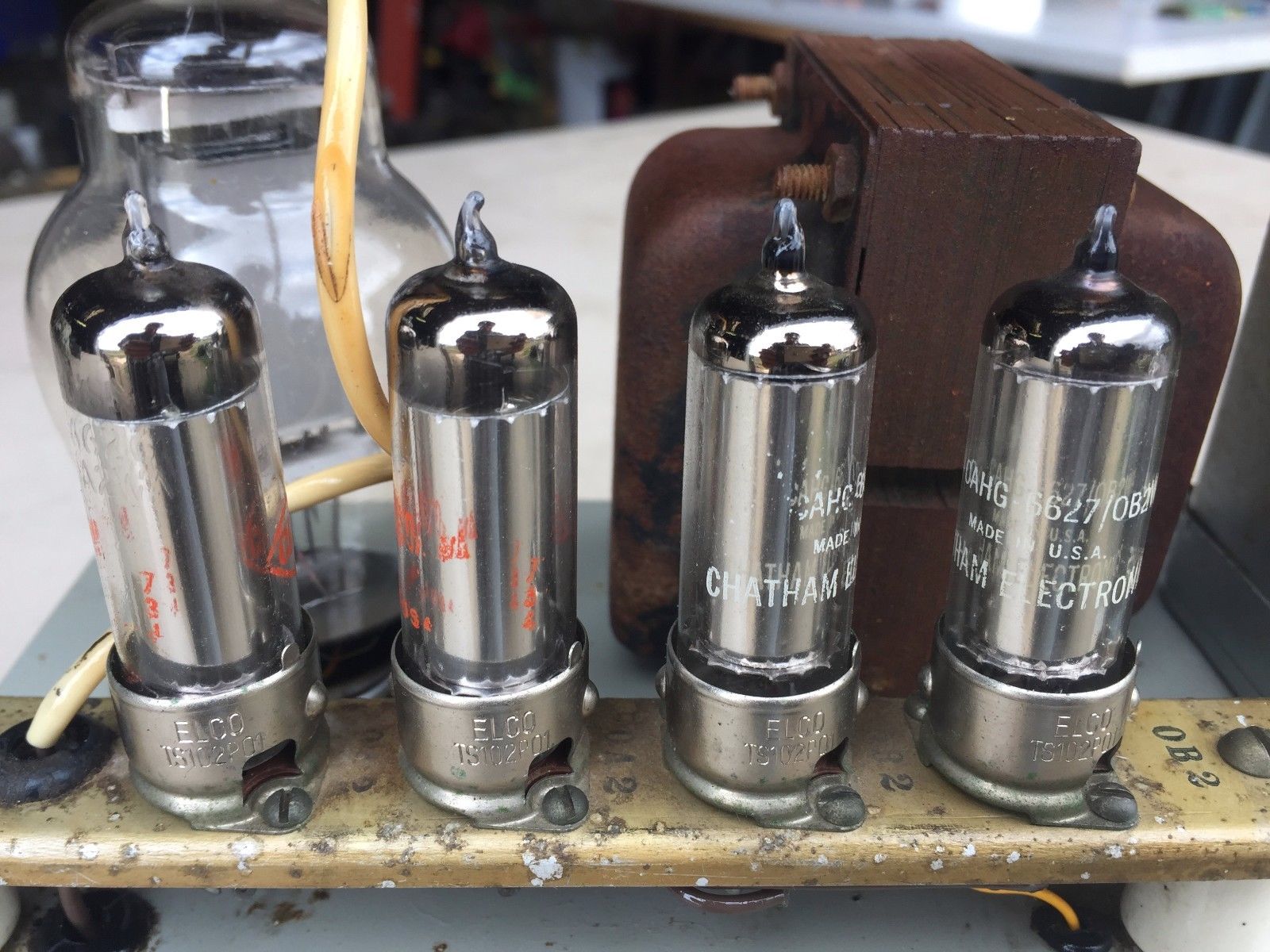
CN-513/WRA-1 Voltage Regulator
CU-701/WRA-1 Line Coupler
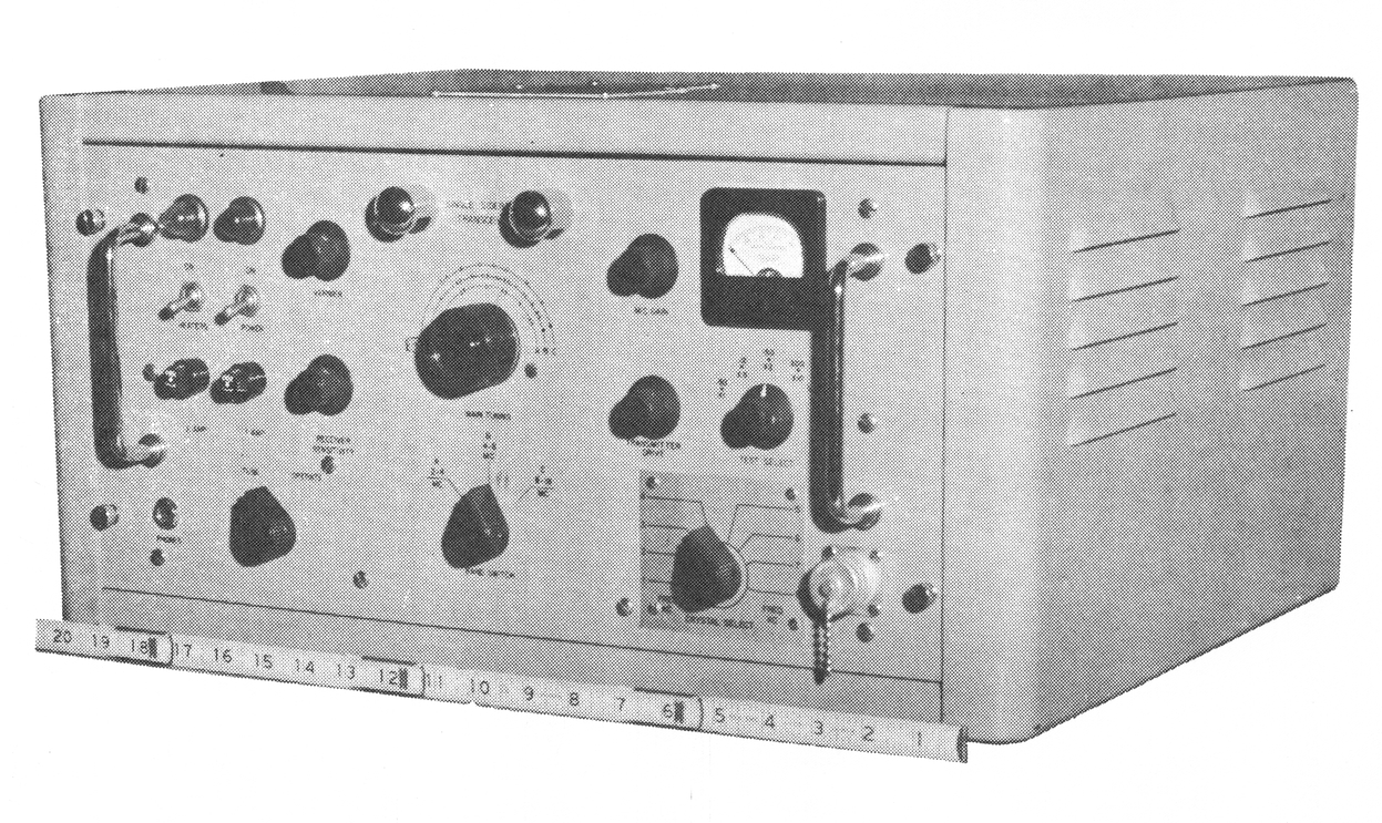
CN-513 is a regulated screen supply for TBL
CU-701 is a buffer amp to drive TBL
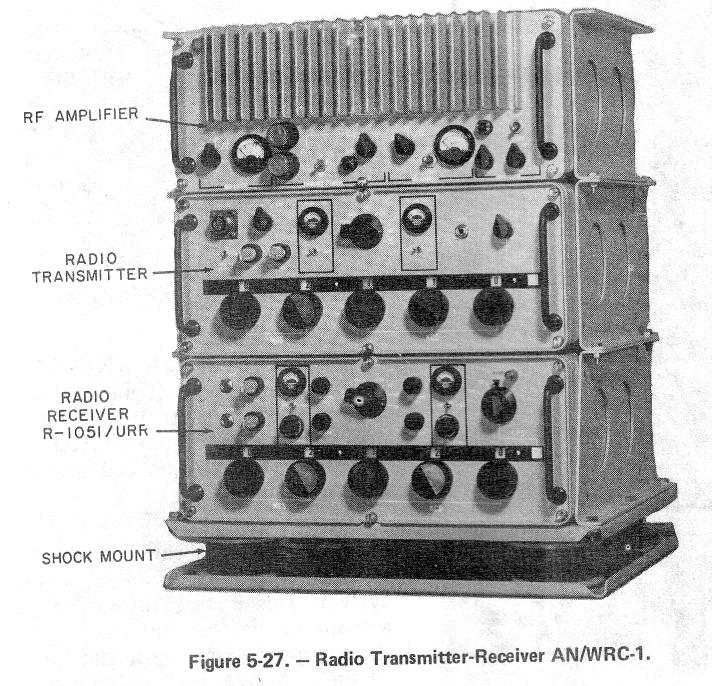
AN/WRC-1
Transmitter-Receiver
AN/WRC-1 procurement
AN/WRC-1B and CU-937/UR Manual
NAVSHIPS 0967-LP-427-5010
- download 40MB pdf
ET A School HF Transmitter/Receiver Sub-Systems (1982)
- covers AN/WRC-1B and AN/URT-23(V)
Vol 3 part 1 - exercises - download
pdf
Vol 3 part 2 - diagrams - download
pdf
2-30mc, 100w
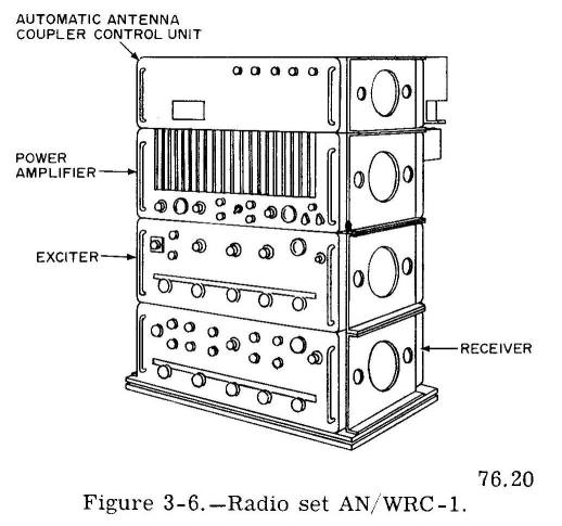
R-1051/URR receiver
T-827/URT exciter
AM-3007/UR power amplifier
CU-937/UR antenna coupler
J-1265/U junction box
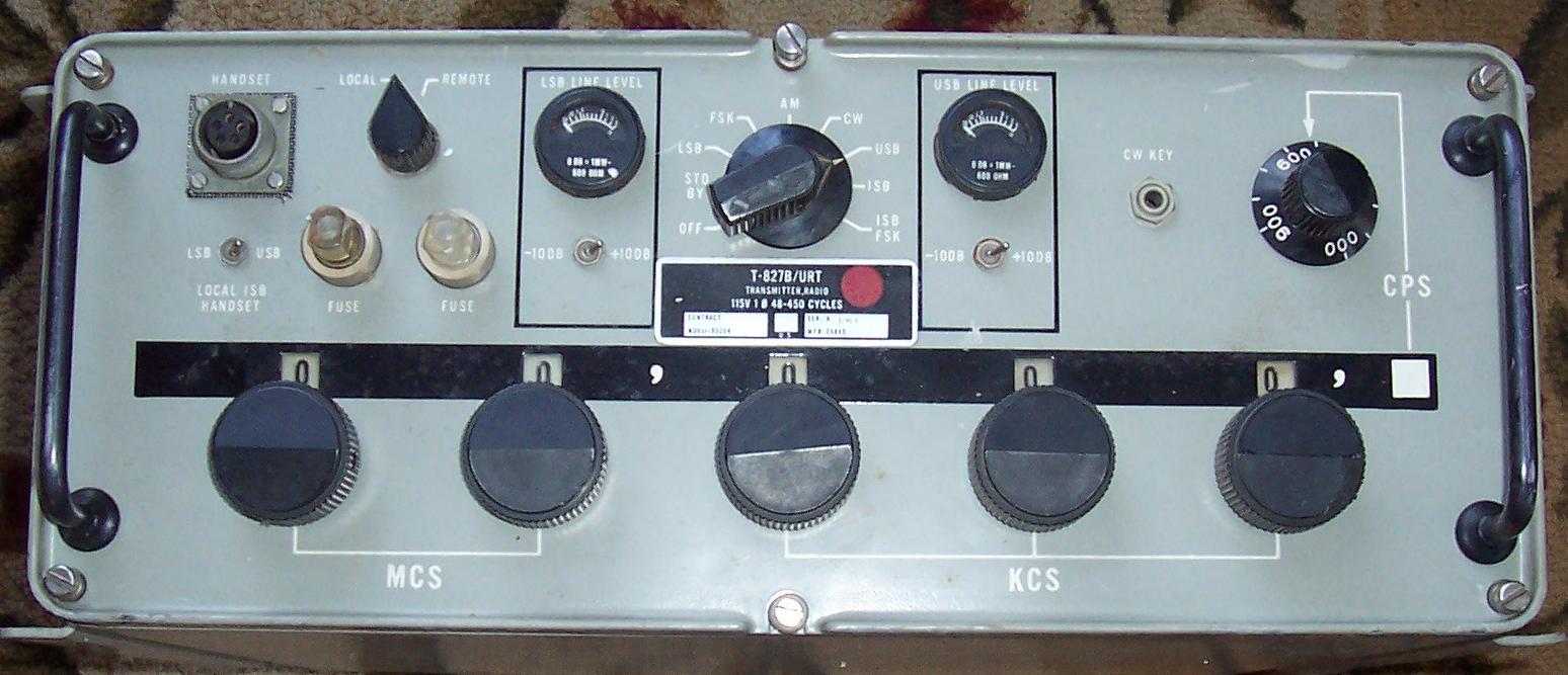
T-827B/URT exciter
predecessor equipment- General Dynamics SC-series
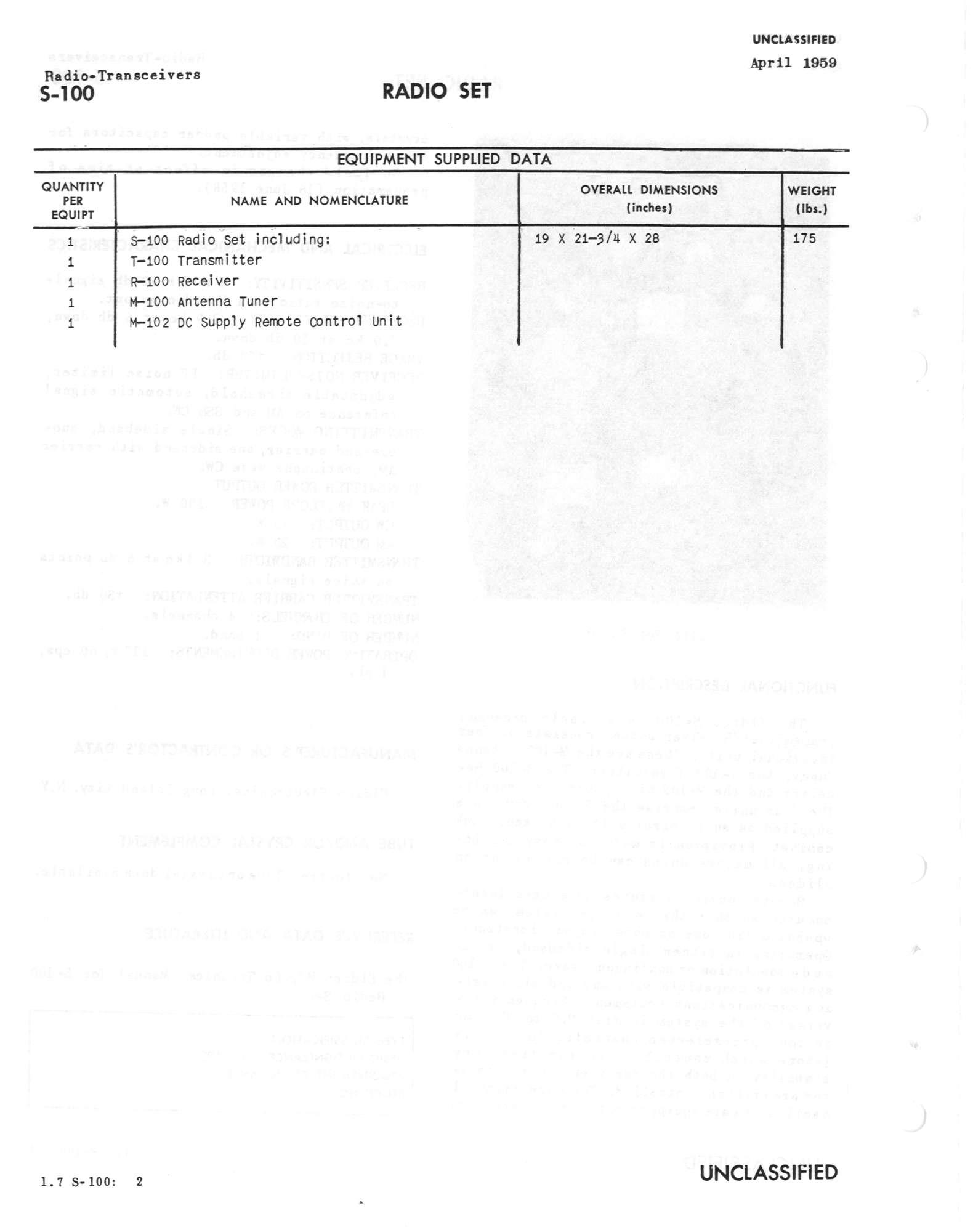
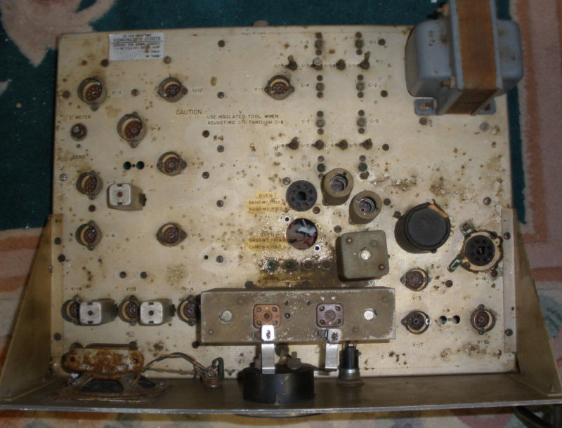
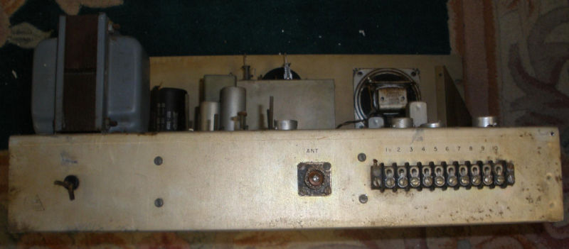
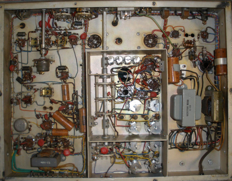
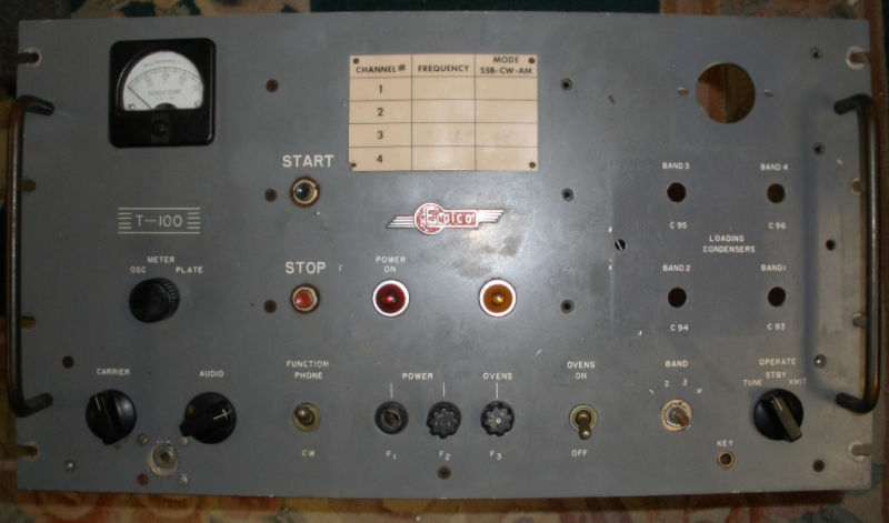
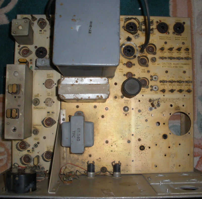
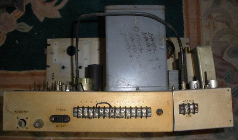
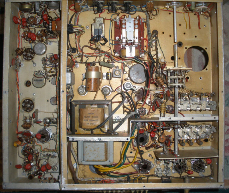
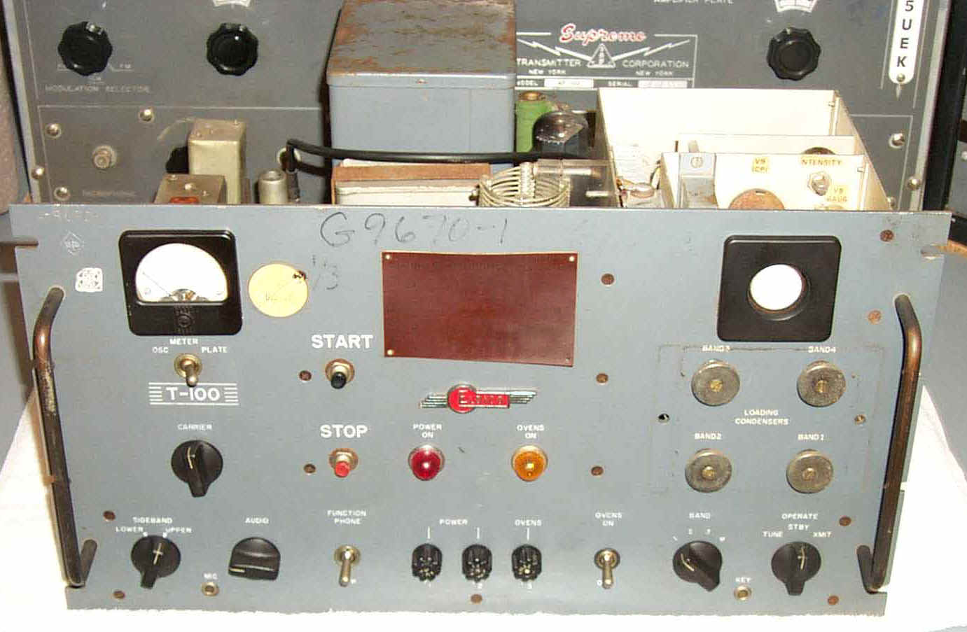
Eldico S-100 SSB transmitter-receiver
1959 spec sheet
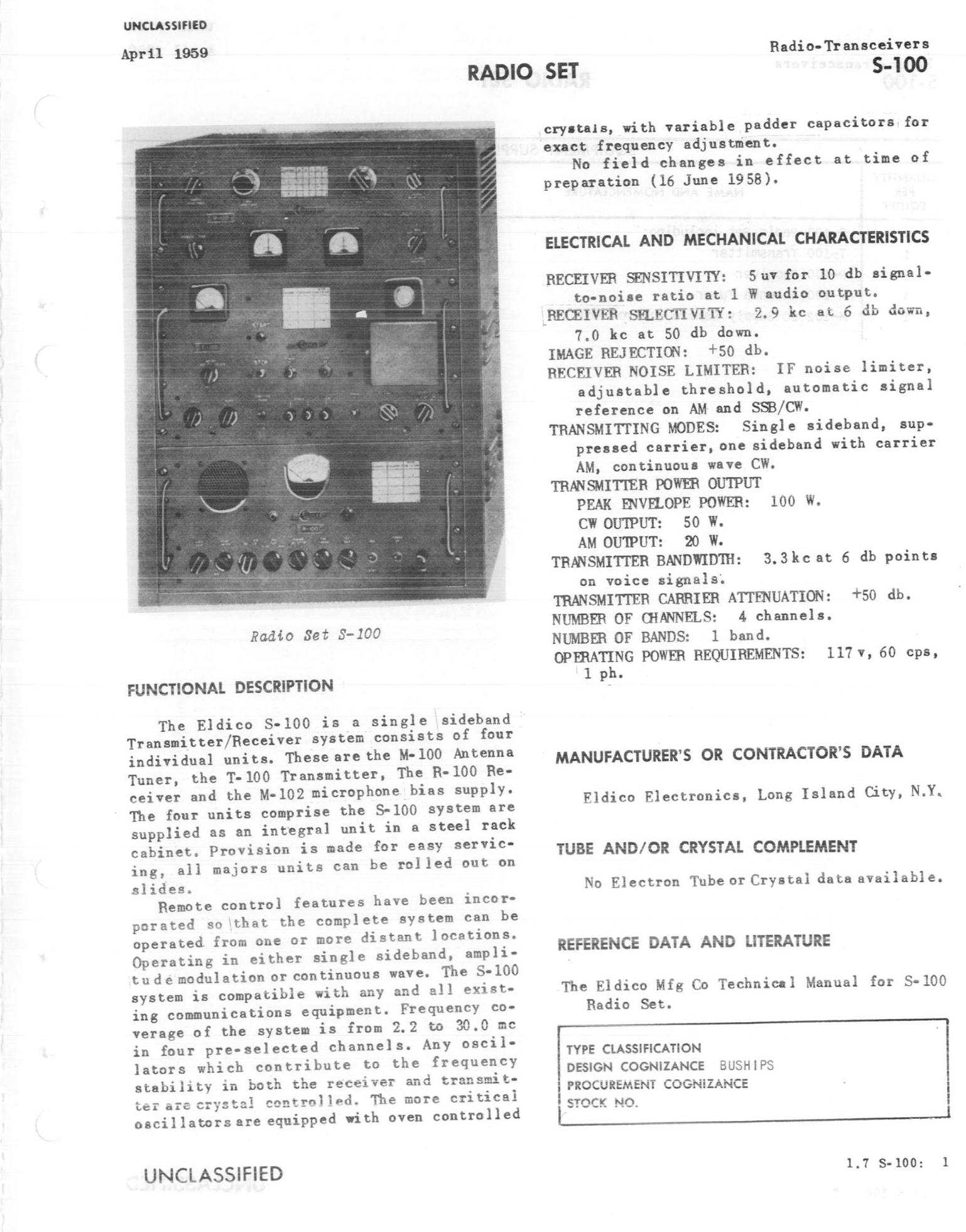
R-100 receiver

R-100 receiver
A small number were installed for interim testing before military SSB equipment was procured.
Included:
R-100 receiver
T-100 transmitter
M-100 Antenna Tuner
M-102 DC supply remote control
Used with SRA-25 antenna tuner
(photos thanks to Brian WA5UEK)

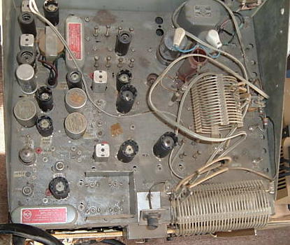
RCA SSB-1 Transceiver
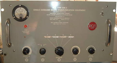
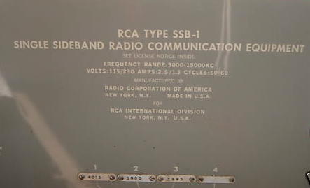
RCA SSB HF transceiver 60 watts
4-channel, crystal controlled 3-15 mc
pair of 6146 output (3x 6146 in later models)
Commercial unit used extensively by USN before military SSB equipment was procured
NAVSHIPS 92917
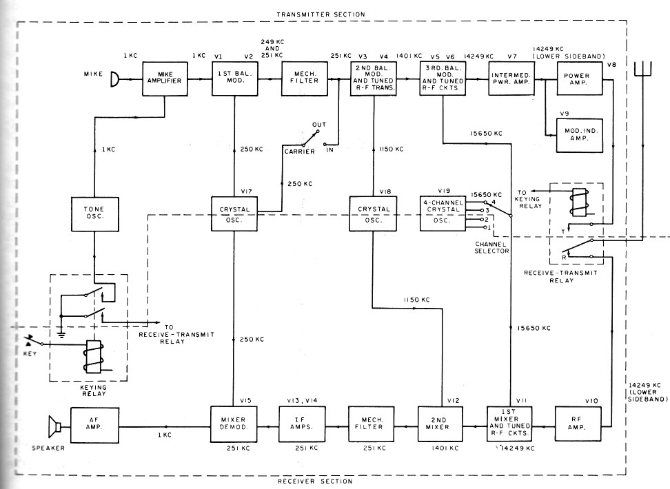
SSB-1 block diagram
used with AN/SRA-20 antenna tuner