Shipboard Receiver & Transmitter Switchboard Interconnections
RECEIVER RF PATCH PANELS - See Receiving RF Patch Panels & Switches |
|||
| - | |||
RECEIVER AF PATCH PANELSAlso see Receiver Site AF/RF Signal Distribution
Units
|
|||
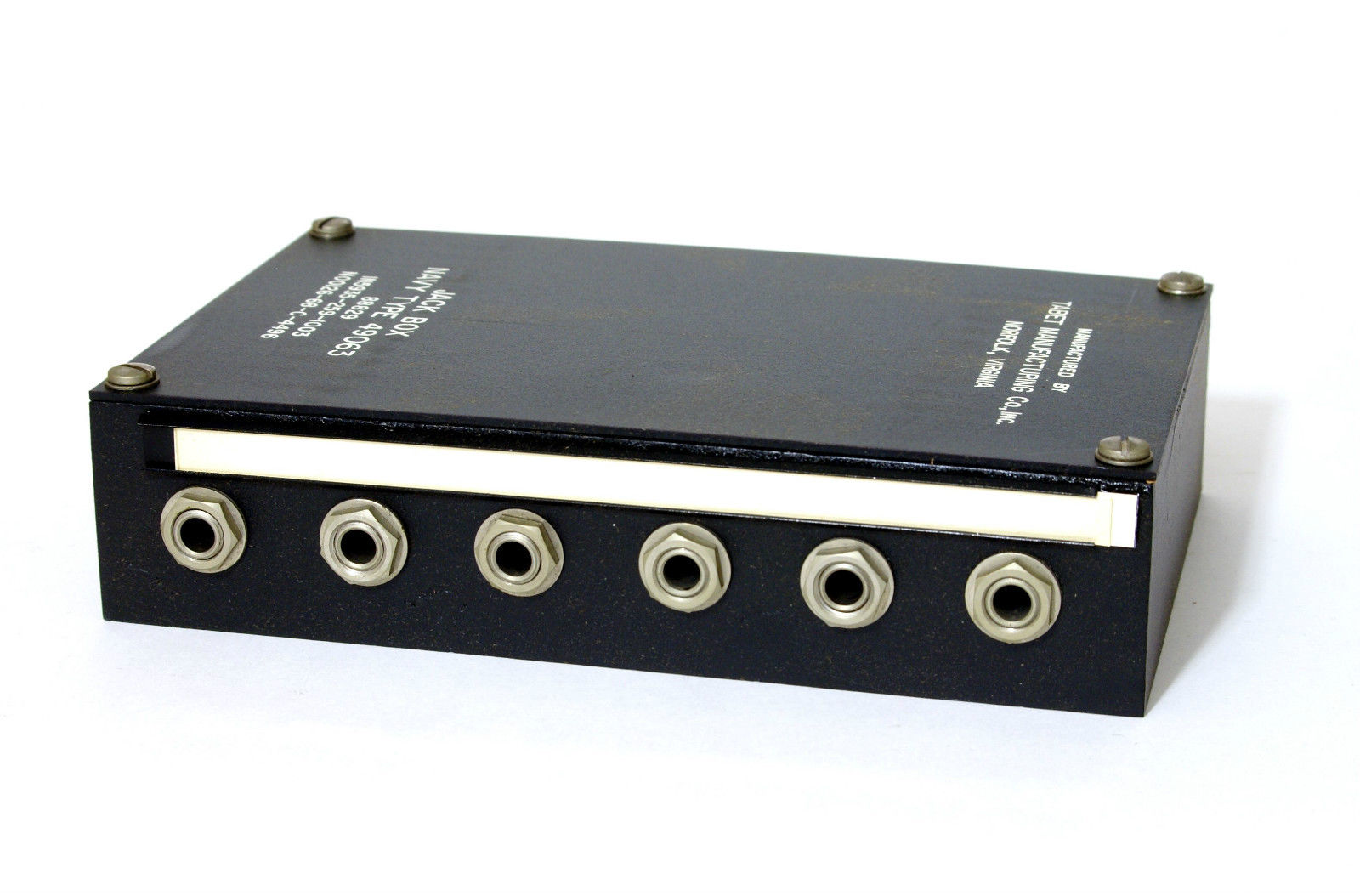
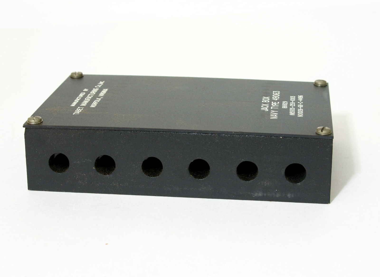
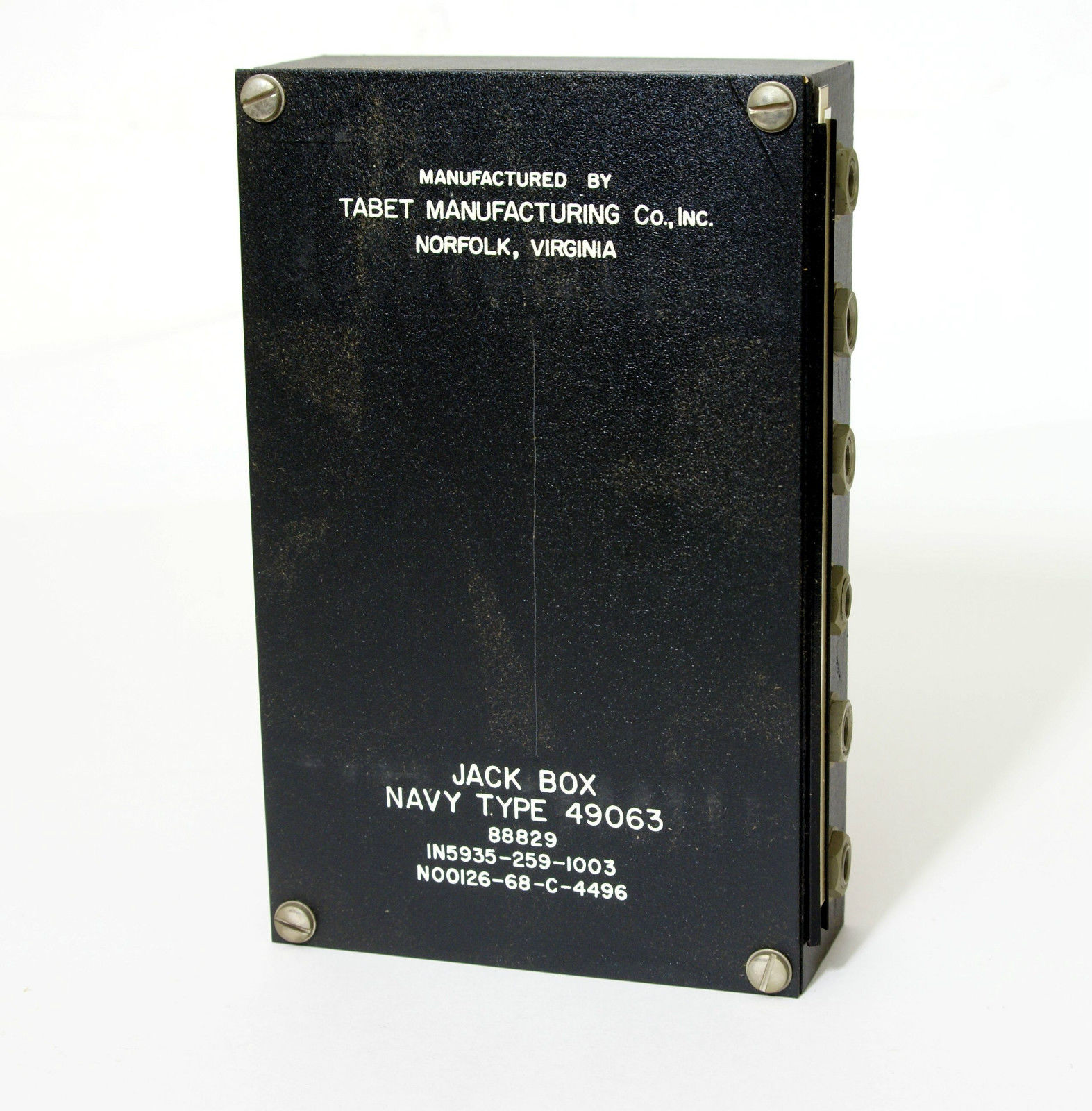
NT-49063 Audio Jack for receiver operating positions |
|
|
|
NT-491394 Audio Jack Panel
|
Two rows of 13-pairs, 2-conductor
|

|
|
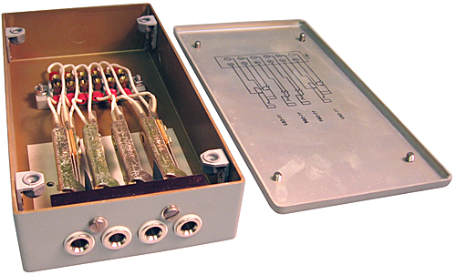
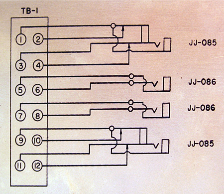
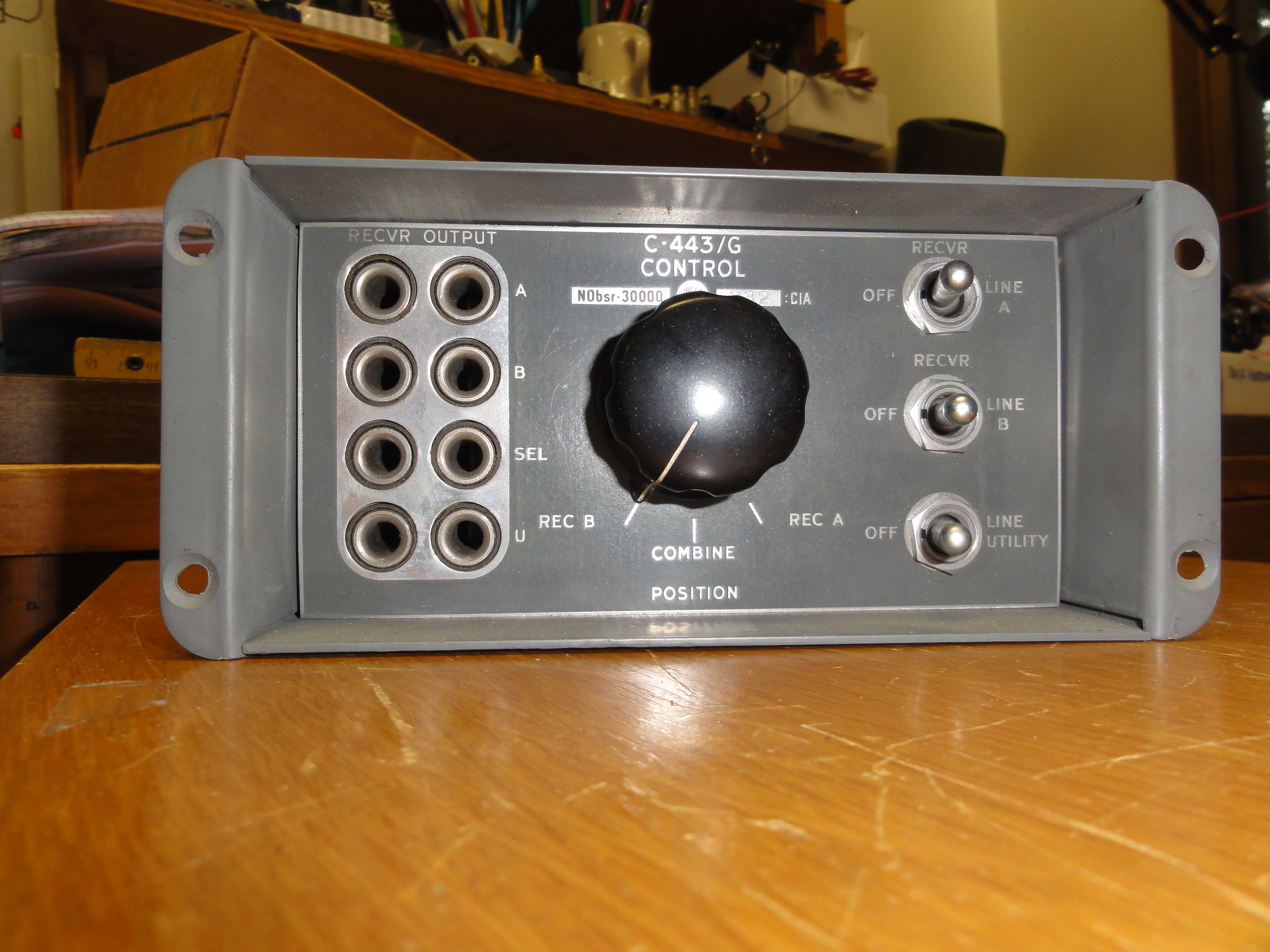
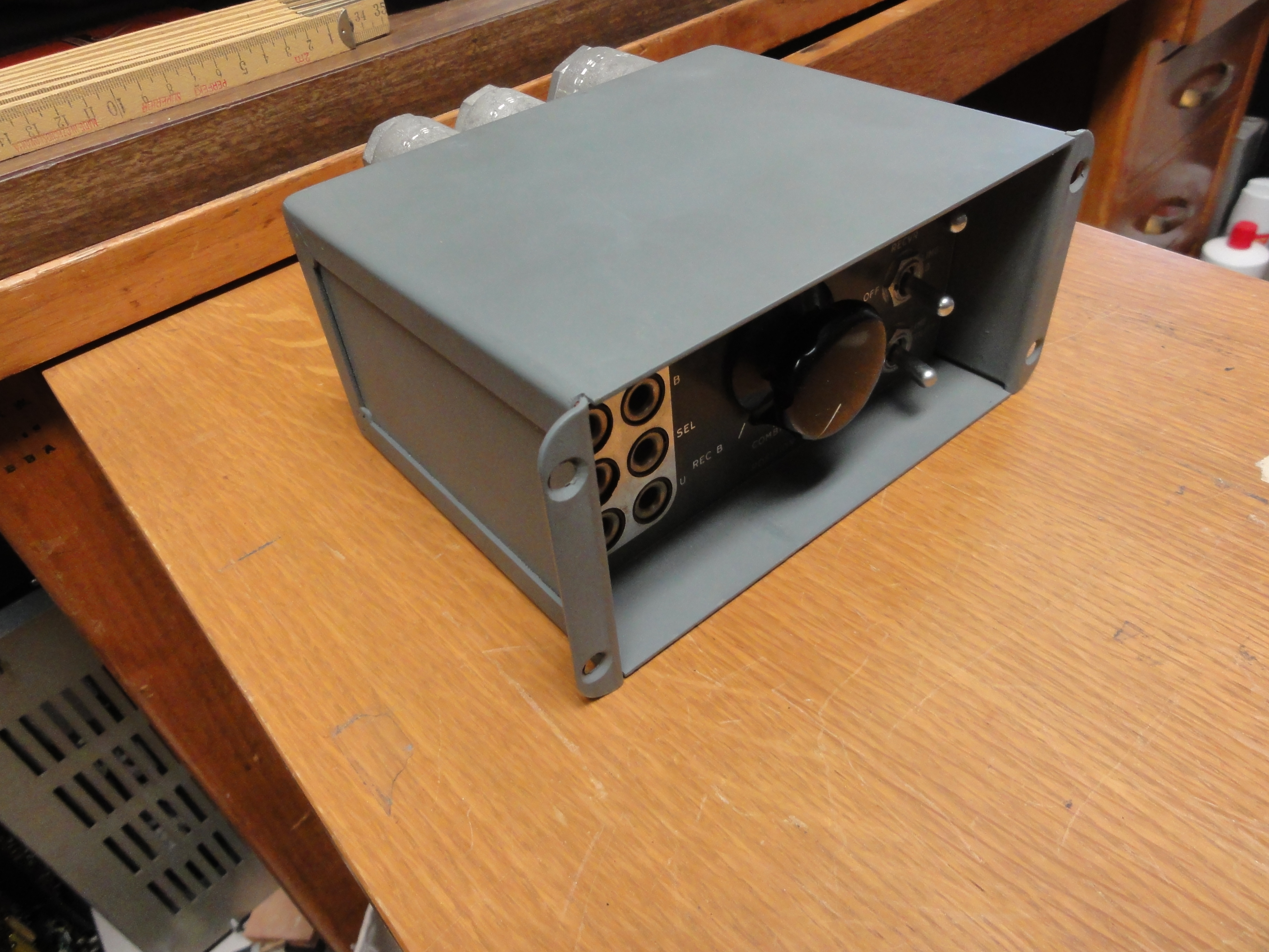
C-443/G AF Control and Jack Box - installed at receiver operating
position
|
C-443/G schematic
|

|

|
J-939B/U Audio Jack Box - typically installed at receiver operating position
|

|
|
|
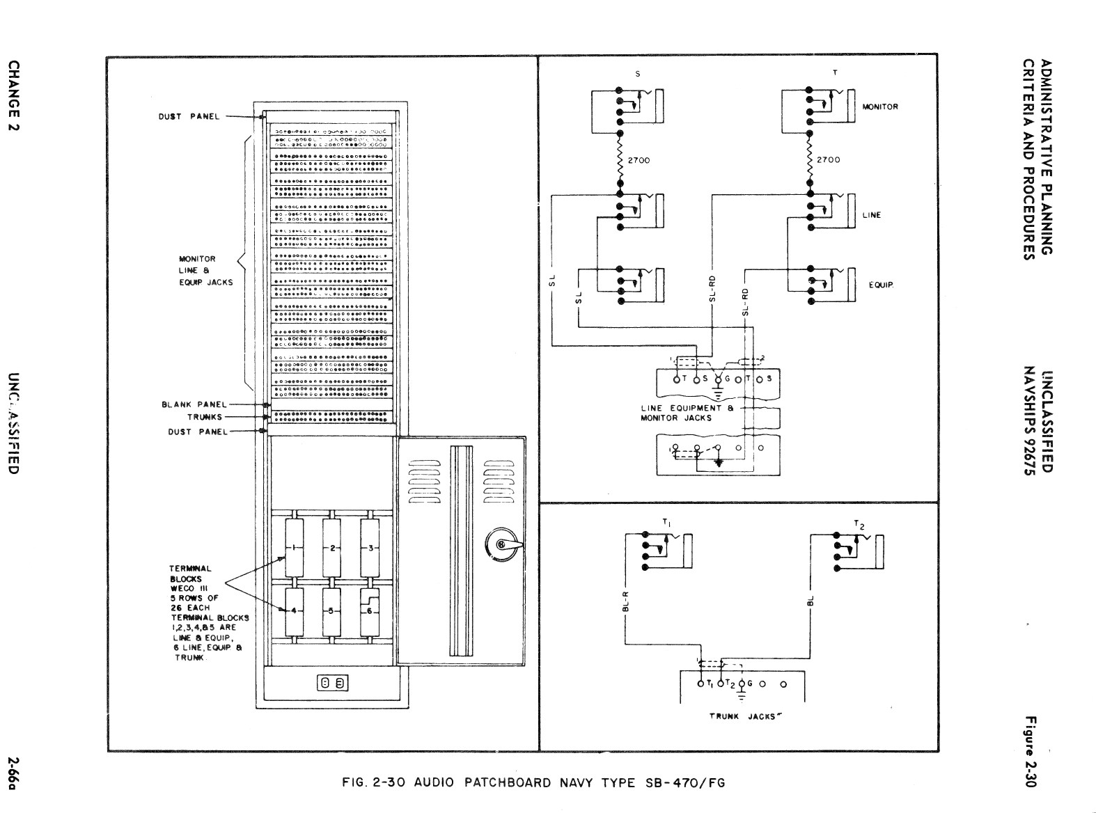
SB-470/FG Comm station audio patch panel
|
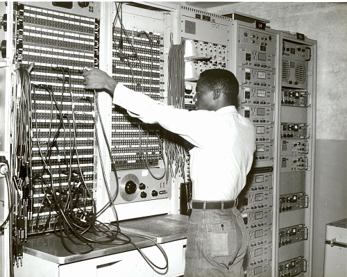 Patchboards at NAVCOMMSTA Guam - Note AN/FCC-3 multiplexer in Rack #14 and TH-39/UGT keyer in Rack #15 |
Older-style audio patch panels always used dual 2-conductor patch
cords - with signal on each tip and shield on the sleeves. |
Also see Receiver Site
AF/RF Signal Distribution Units
Newer-style audio patch panels used 3-conductor patch cords, with signal lines on tip and ring, and shield on sleeve. If the transmit-and-receive side of a communications circuit is wired to adjacent jack fields, a dual patch-cord assembly may be used to patch both sides of the circuit simultaneously. |
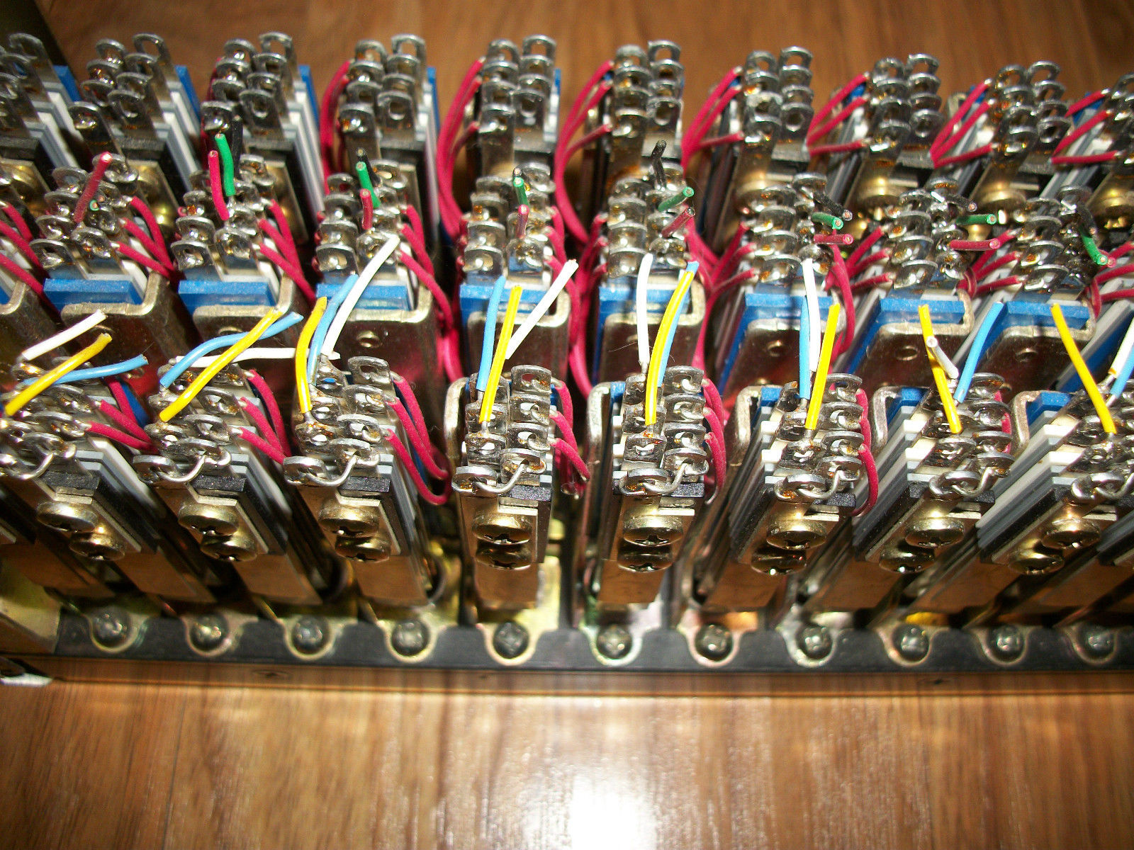
SB-3092/U audio patch panel
|
These are 3-conductor jacks - signal lines are on tip and ring, shield
on sleeve.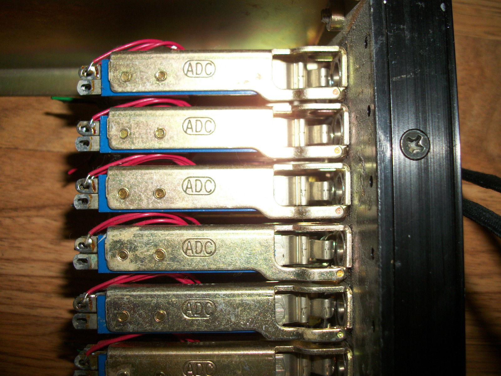 |
 |
 |
|
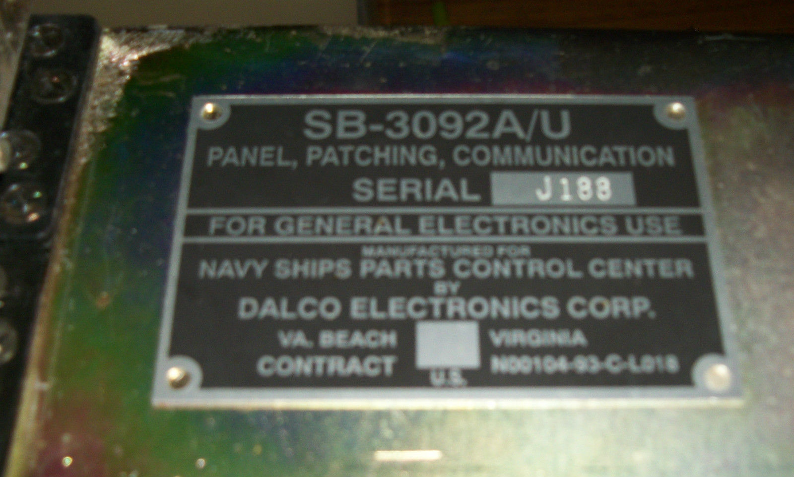
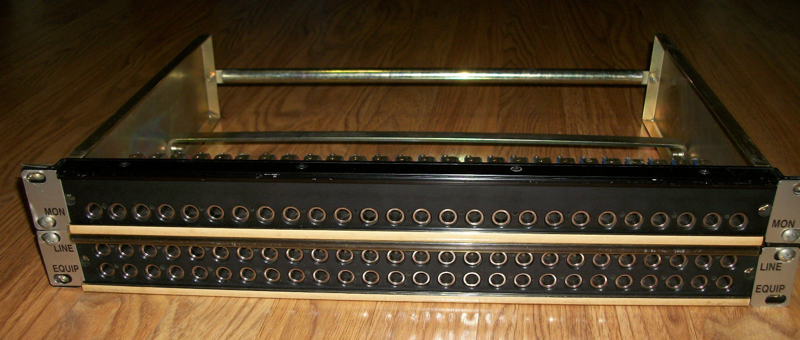
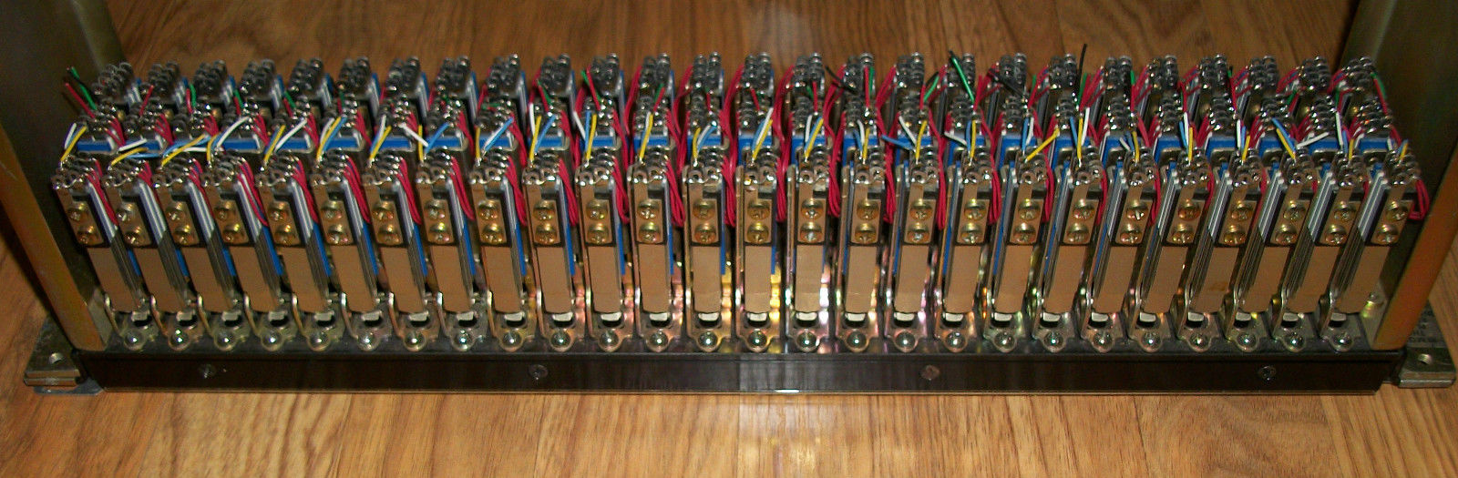
COMMUNICATIONS PATCH PANEL, SB-3092A/U - This is an audio
circuit communications patch panel. It has three rows of 26 jacks, each
mounted on an open frame suitable for installation on a 19-inch rack.
Connections to the panel are facilitated by a terminal block mounted at
the rear of the frame (missing in photos above) |
|||
NT-491397 |
24" patch cord with NT-491242 plugs |
What numbers for other lengths? | manuf CN-491242 manuf CN-491397 National Electric Machine |
| -- | |||
AF Level Meters |
|||
ID-1185/FRA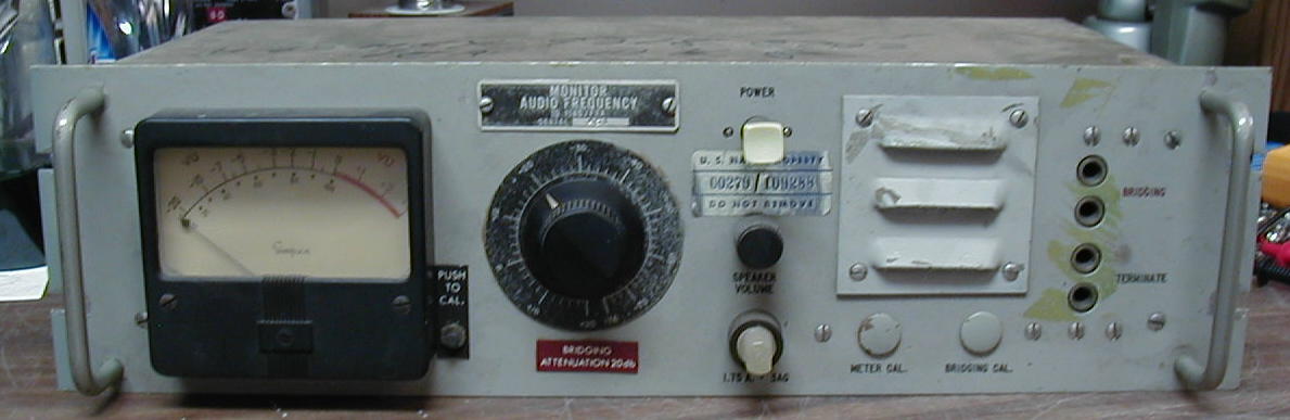 AF level meter + amp & speaker |
 |
 |
Used in COMMSTA AF/RF Signal Distribution Unit
transistorized - note - schematic is printed on bottom cover |
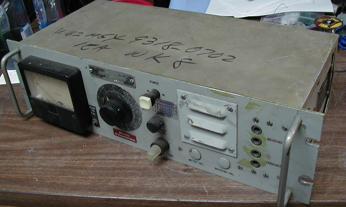
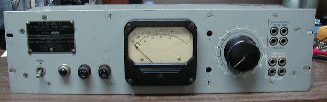
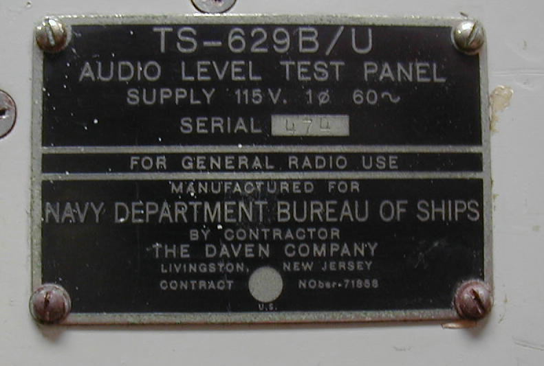
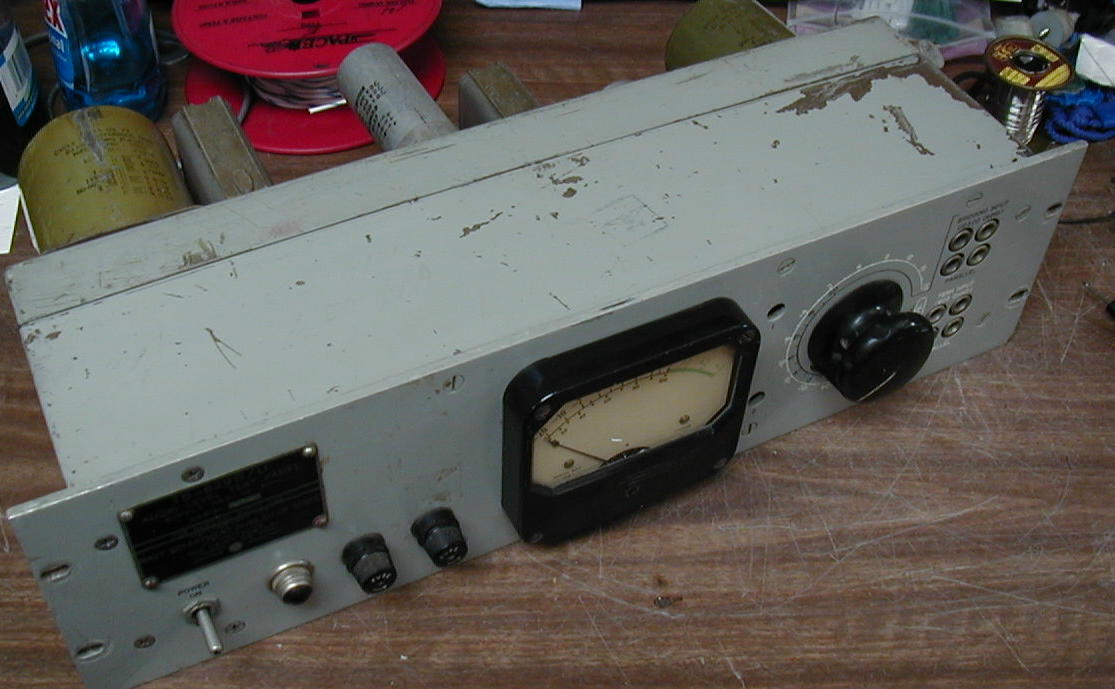
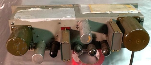
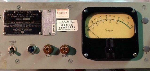
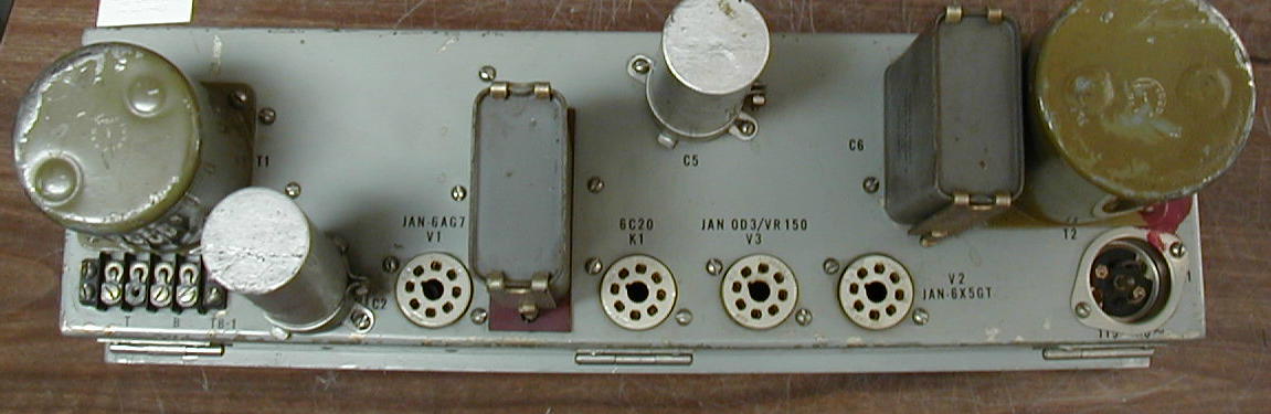
TS-629B/U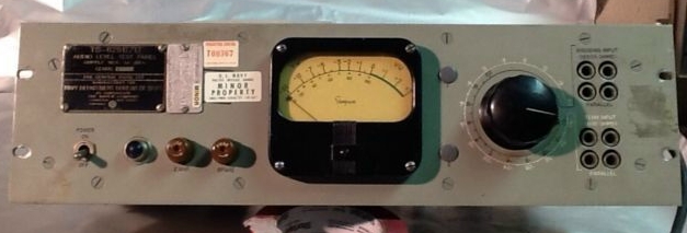
|
AF level meter
|
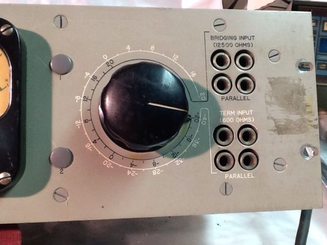 |
Used in COMMSTA AF/RF Signal Distribution Unit
- barely visible at upper left of Guam photo above.
octal tubes - note - schematic is inside unit Manual for TS-629A/U |
|
 |
 |
-- |
| -- | |||
RECEIVER AF TRANSFER SWITCHBOARDS |
|||
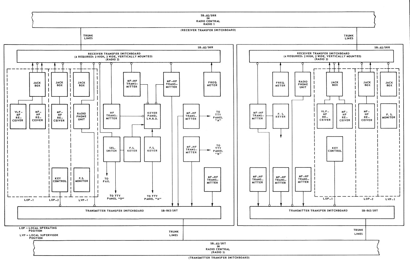
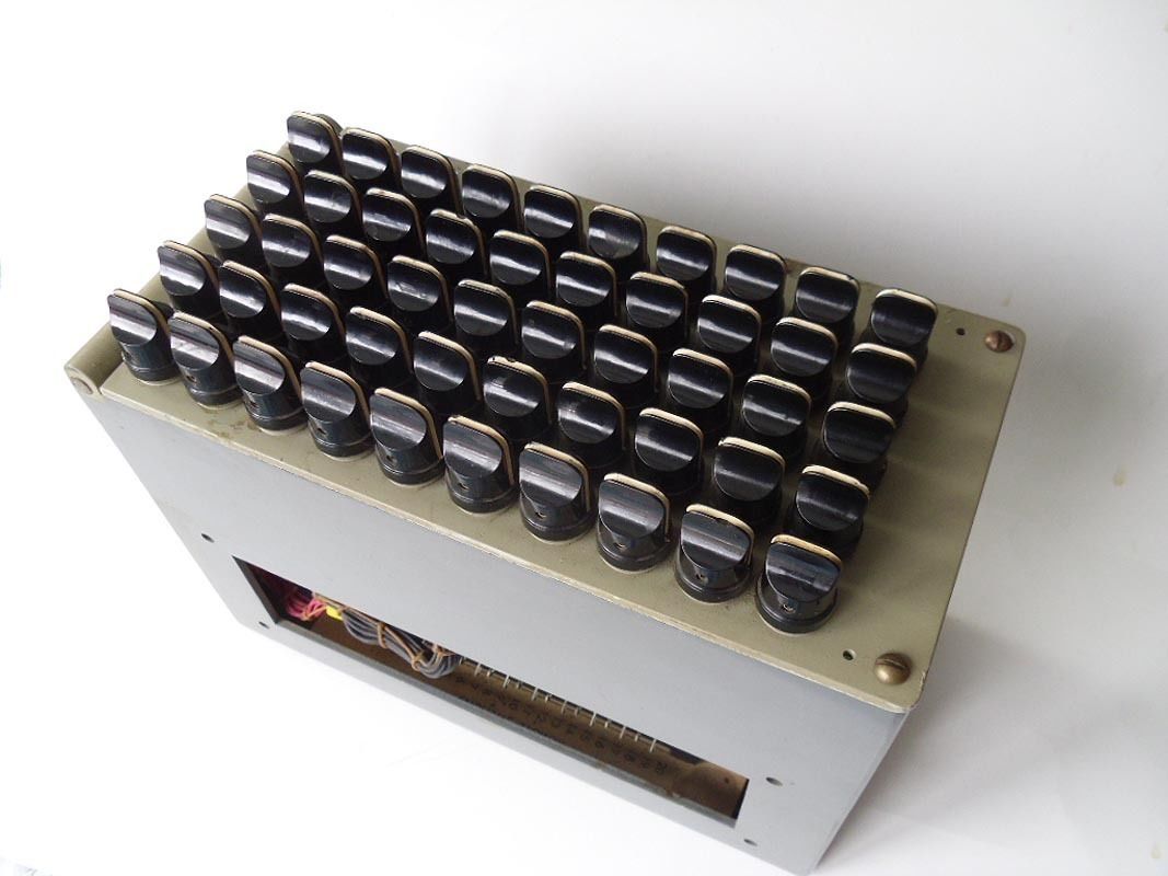
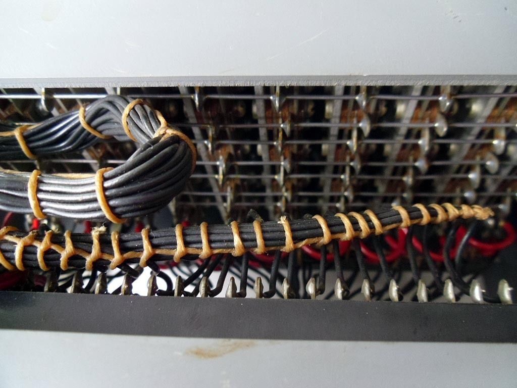
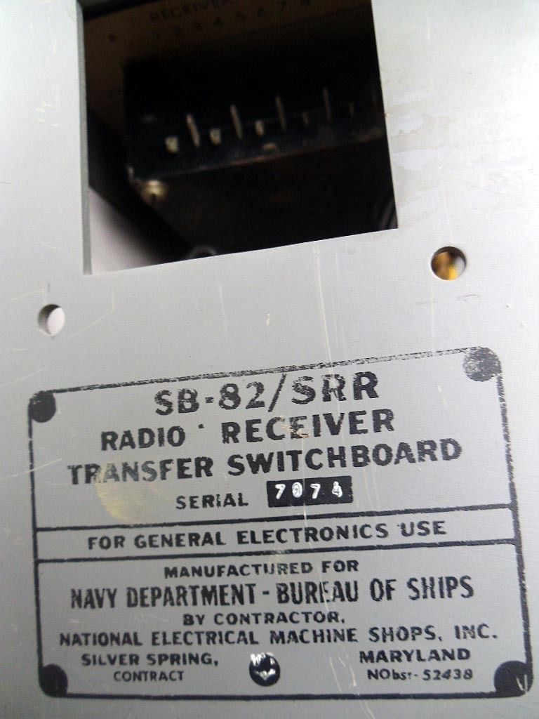
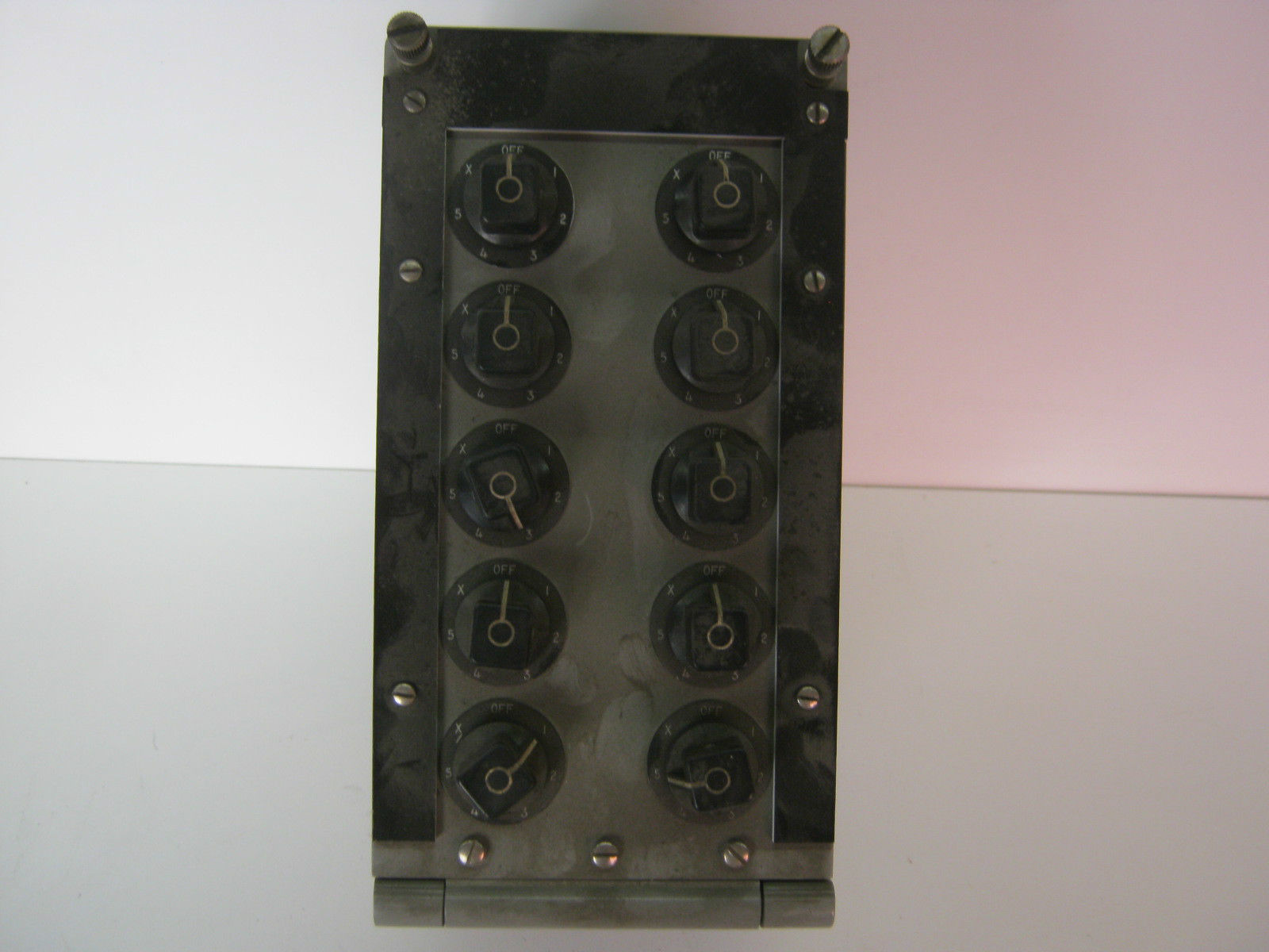
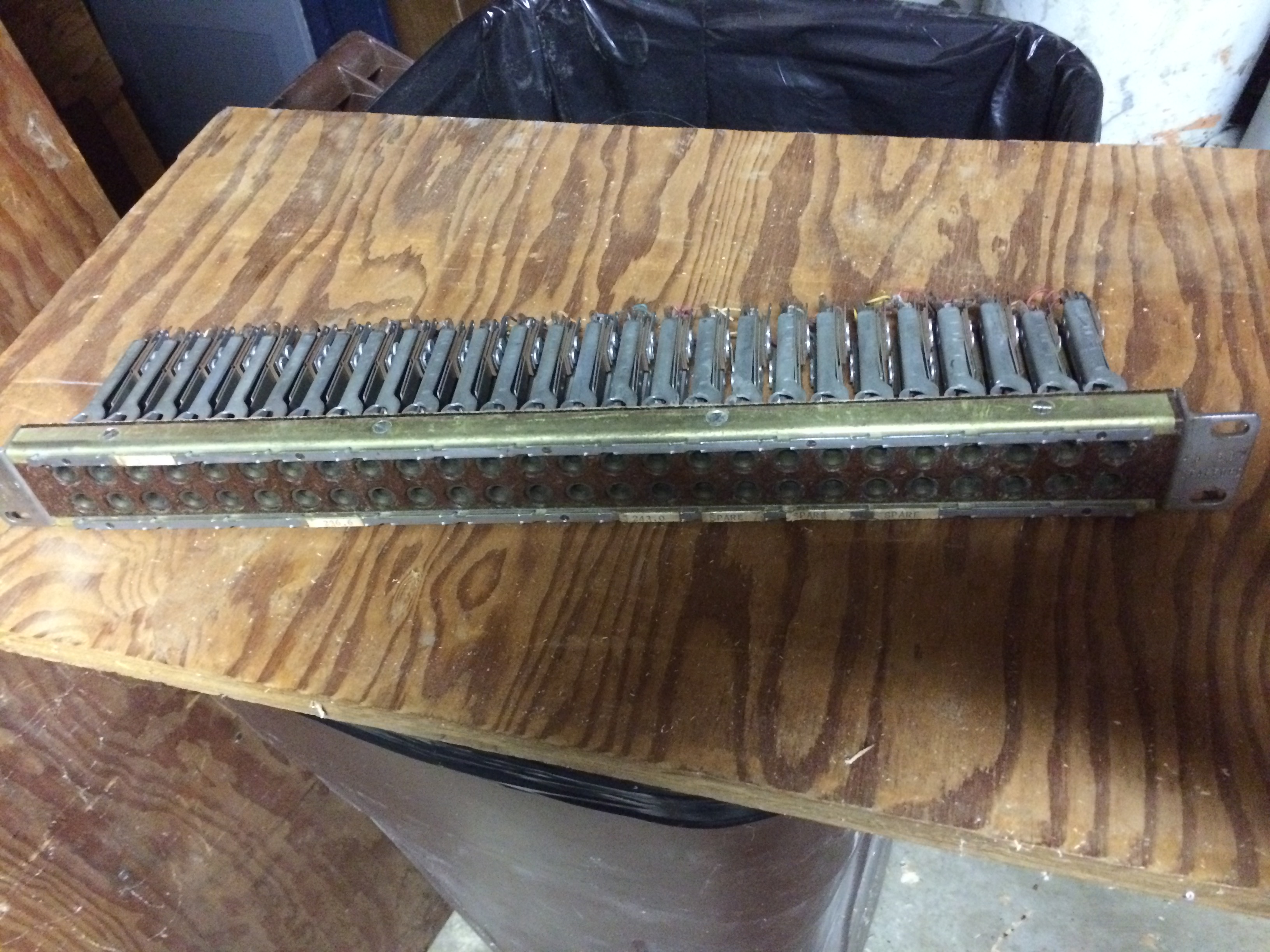
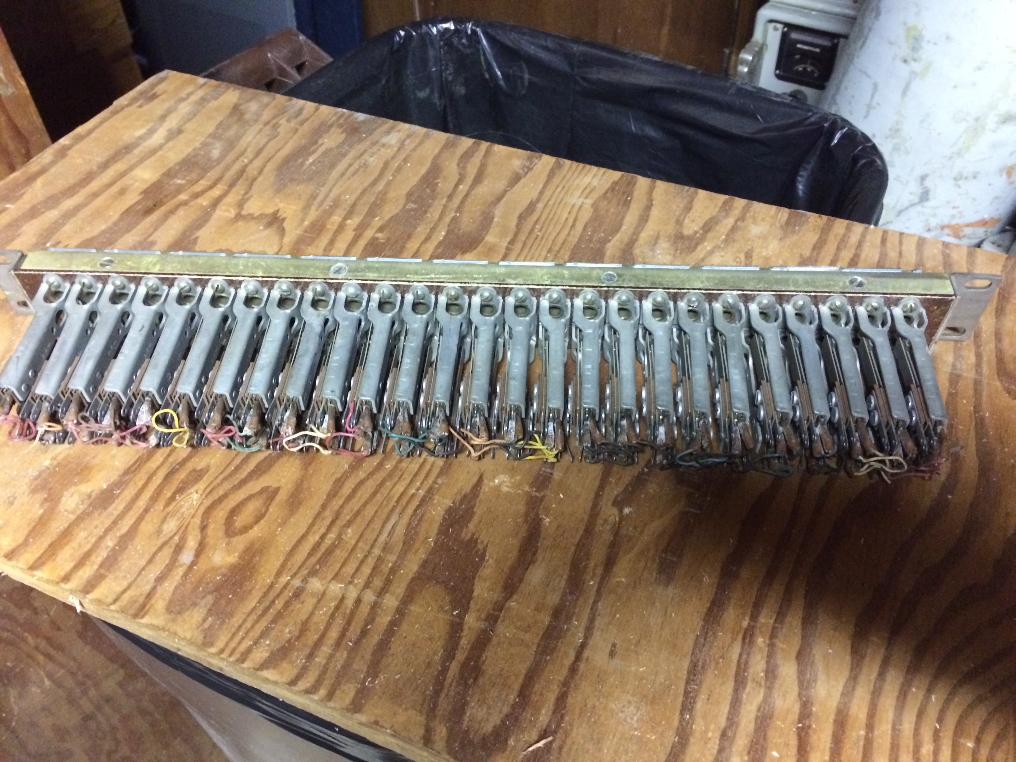
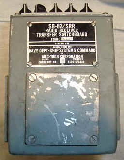
SB-82/SRR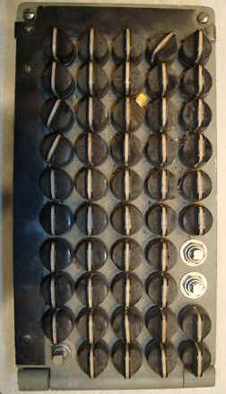 |
AF switching 10 remotes, 5 receivers (10 outputs, 5 inputs)
|
 |
SB-82/SRR manual
Spec Sheet - thanks to HNSA
|
 |
|

|
|
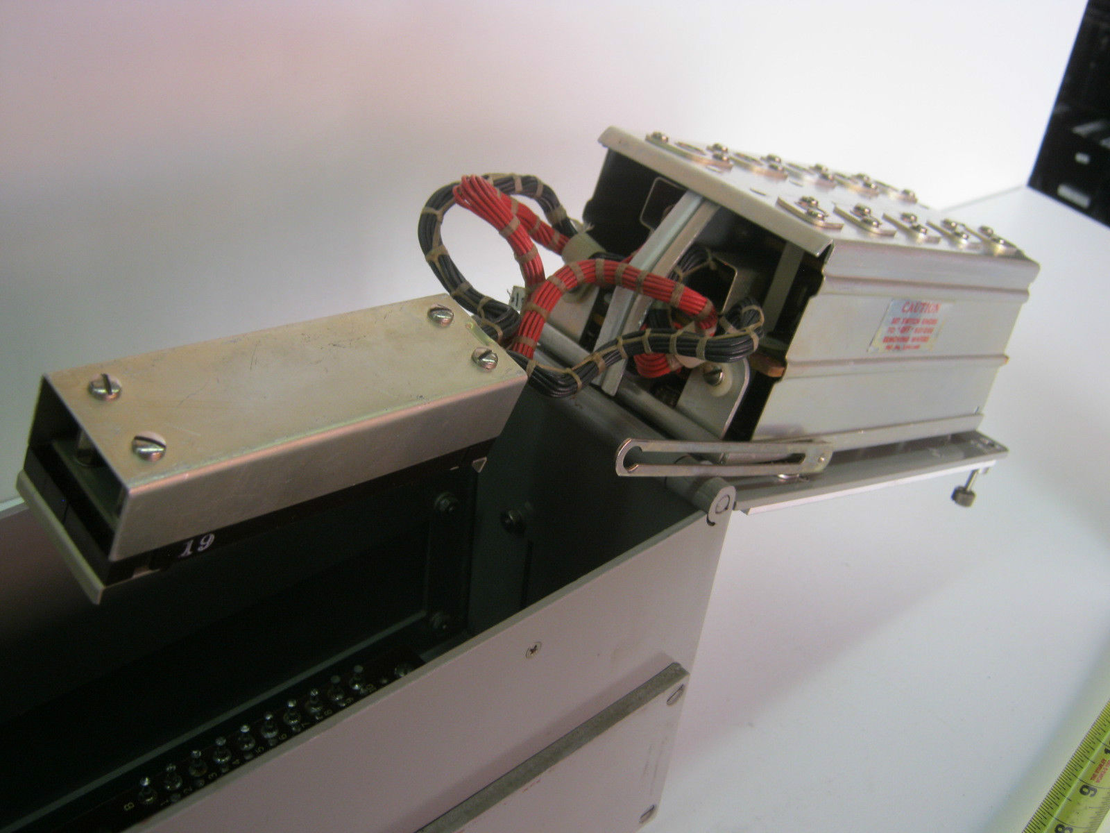
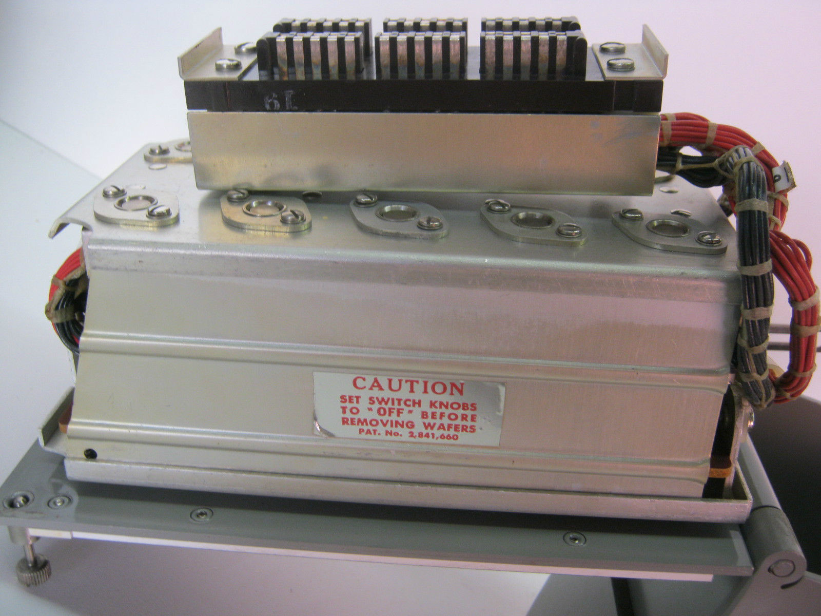
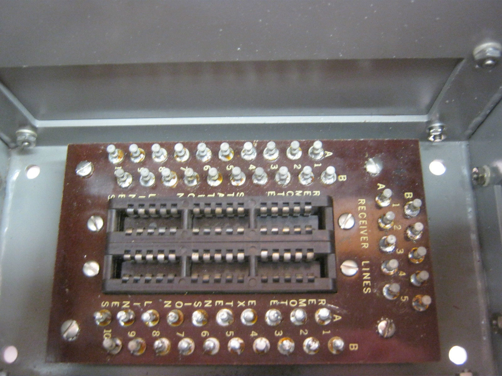
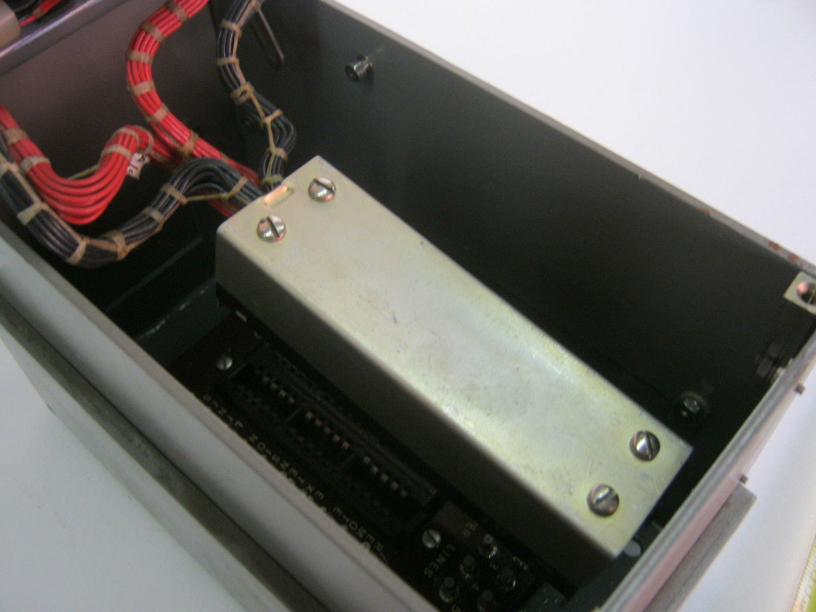
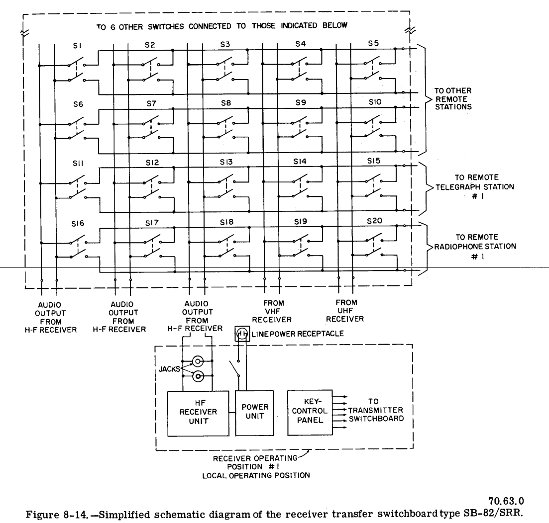
| Receiver transfer switchboard, type
SB-82/SRR, is shown above. The receiver switchboard has five vertical rows
of ten single-throw (ON-OFF) switches that are continuously rotatable in
either direction. One side of each switch within a vertical row is wired
in parallel with the same sides of the other nine switches within the row.
Similarly, the other side of each switch is wired in parallel horizontally
with the corresponding sides of each of the other four switches in a
horizontal row. This method of connecting the switches permits a high
degree of flexibility. In general, there are more remote stations than radio receivers, hence the audio outputs five receivers are fed to the five vertical rows and ten remote stations are connected the ten horizontal rows. With this arrangement, a selected receiver output is connected to any or all of the remote stations by closing the proper switch(es). When one switchboard is inadequate for accommodating all of : receivers and remote stations installed in ship, several of these switchboards are mounted together and interconnected so that they form a bank of switchboards. The knob of each switch is marked with heavy white line to provide visual indication of whether the switch is in the ON or OFF position Switchboards always are installed with the line positioned vertically when the switch is open (off). To further standardize all installations, receivers usually are connected to the vertical rows of switches, and remote stations are connected to the horizontal rows. Identification of the receivers and remote stations is engraved on the laminated bakelite label strips fastened along the top and left edges of the panel front. |
|||
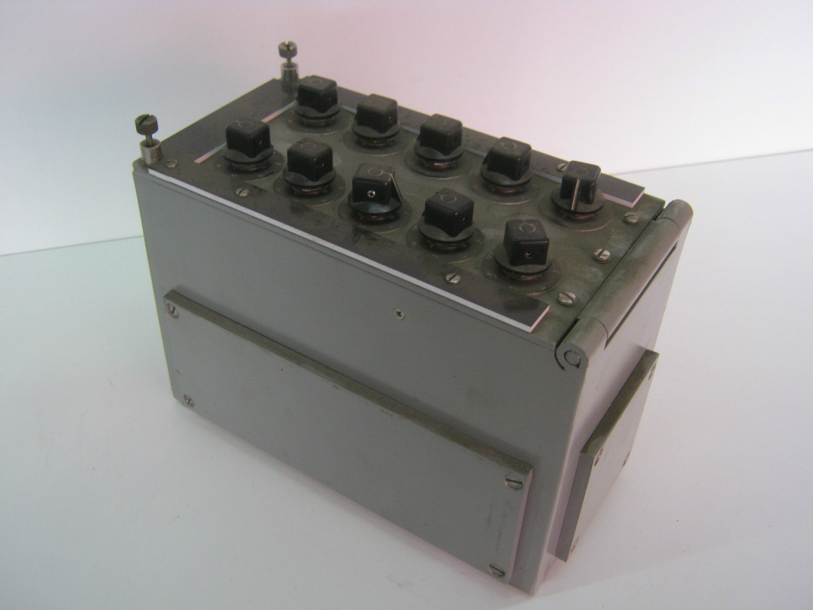
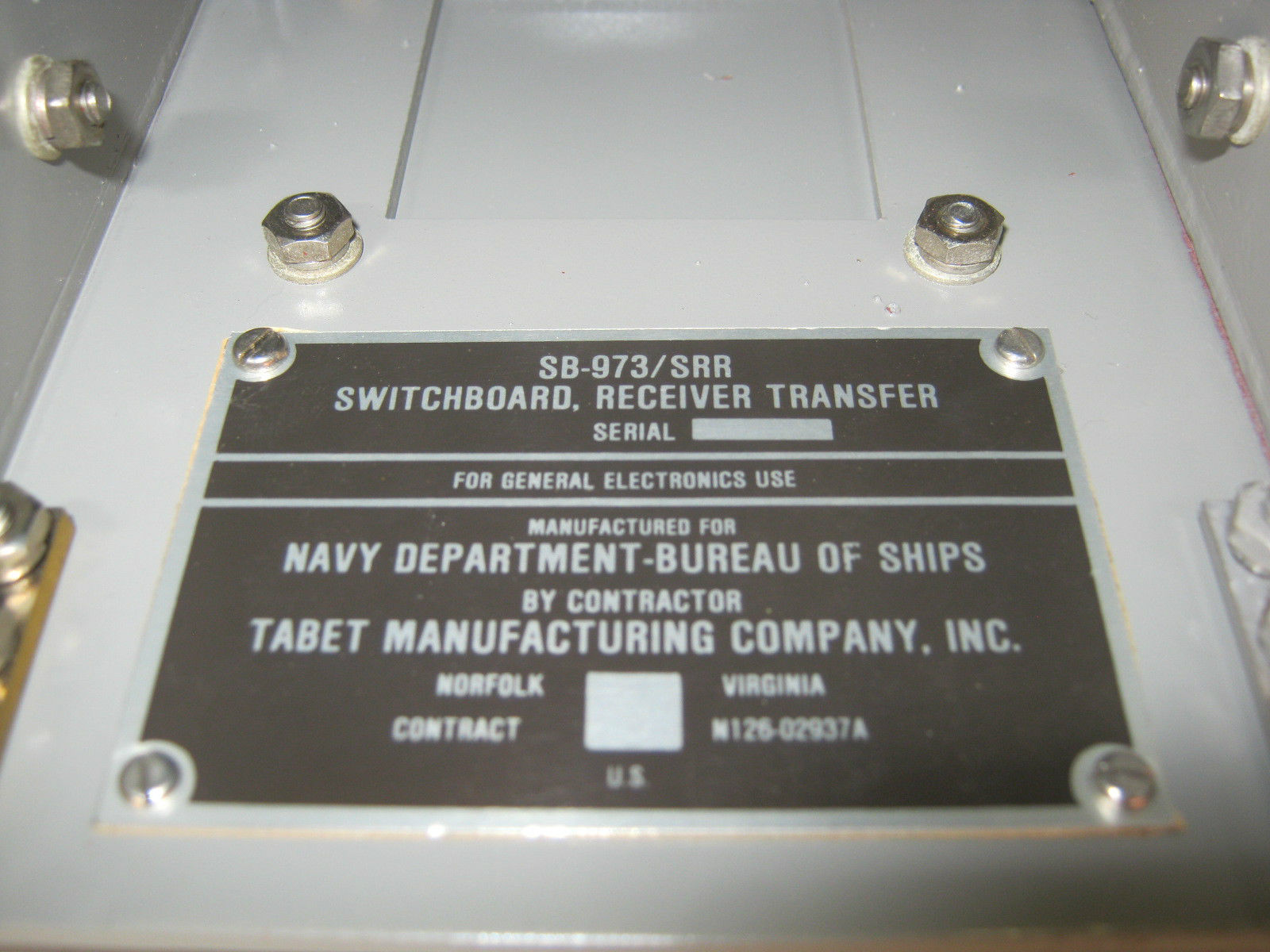
SB-973/SRR |
SB-973/SRR aboard DLG-30
|
|
|
 |
|
|
|
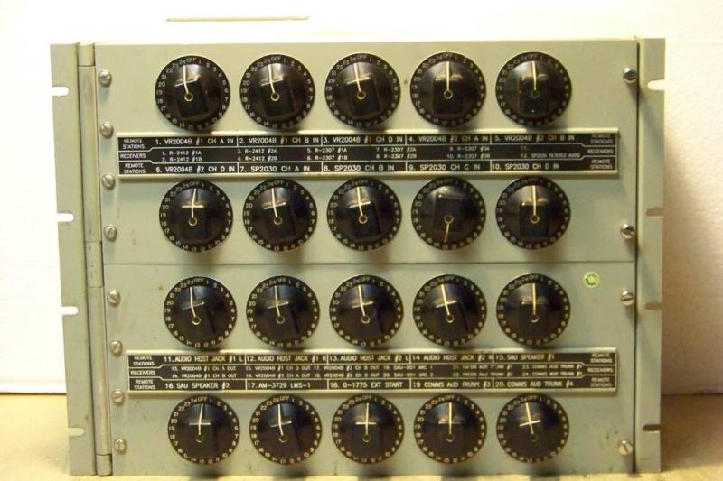
| SB-973/SRR - AF switching - 10 remotes, 5 receivers
- pdf manual A more recent model receiver transfer switchboard is the SB-973/SRR, illustrated above. This switchboard contains 10 seven position rotary selector switches. Each switch or operating knob relates to a remote control station Switch positions one through five relate to receivers. Position X on each switch serves to transfer the remote control stations connected to the original switchboard to the corresponding switches in additional switchboards. In this manner, any number of receivers can be connected to the ten remote control stations. An additional switchboard is needed for each five additional receivers. Switchboards providing facilities for additional remote control stations are mounted in vertical sequence, whereas those containing additional receivers are mounted in horizontal sequence. |
|||
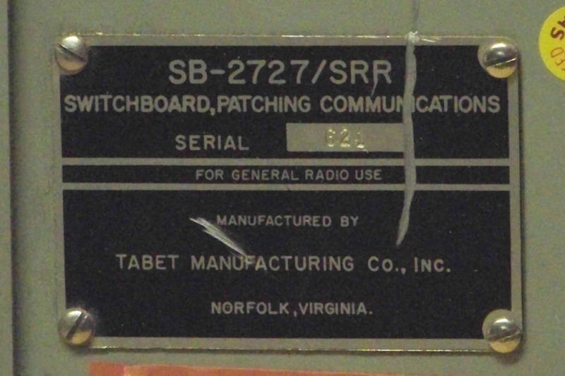
SB-2727/SRR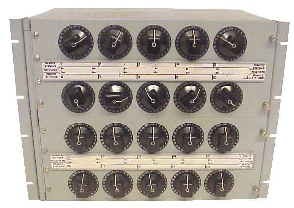 |
AF switching 20 remotes, 24 receivers
|
 |
NAVSHIPS 0969-124-8010 |
 |
 |
 |
- |
AUDIO AMPLIFIERS & LOUDSPEAKERS |
|||
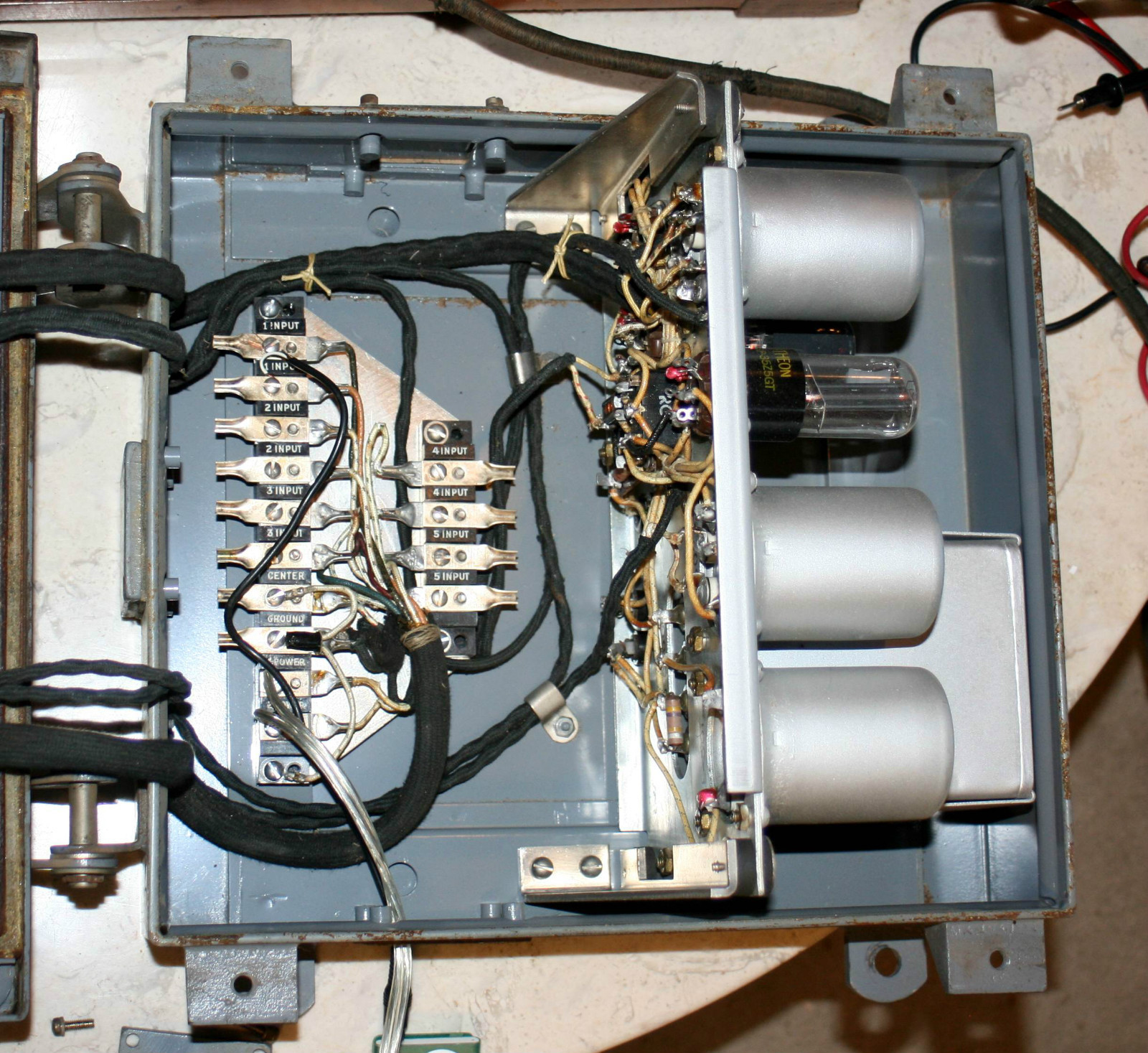
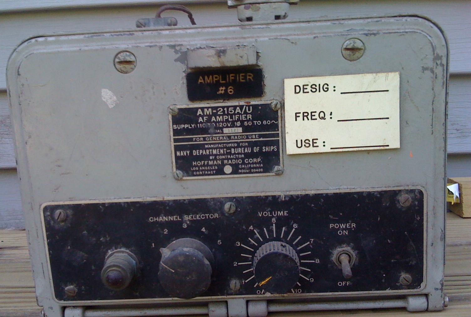
AM-215/U
|
5 inputs, 10 watts output
|
AM-215 Info Page -
Photos and Spec Sheets for
all models
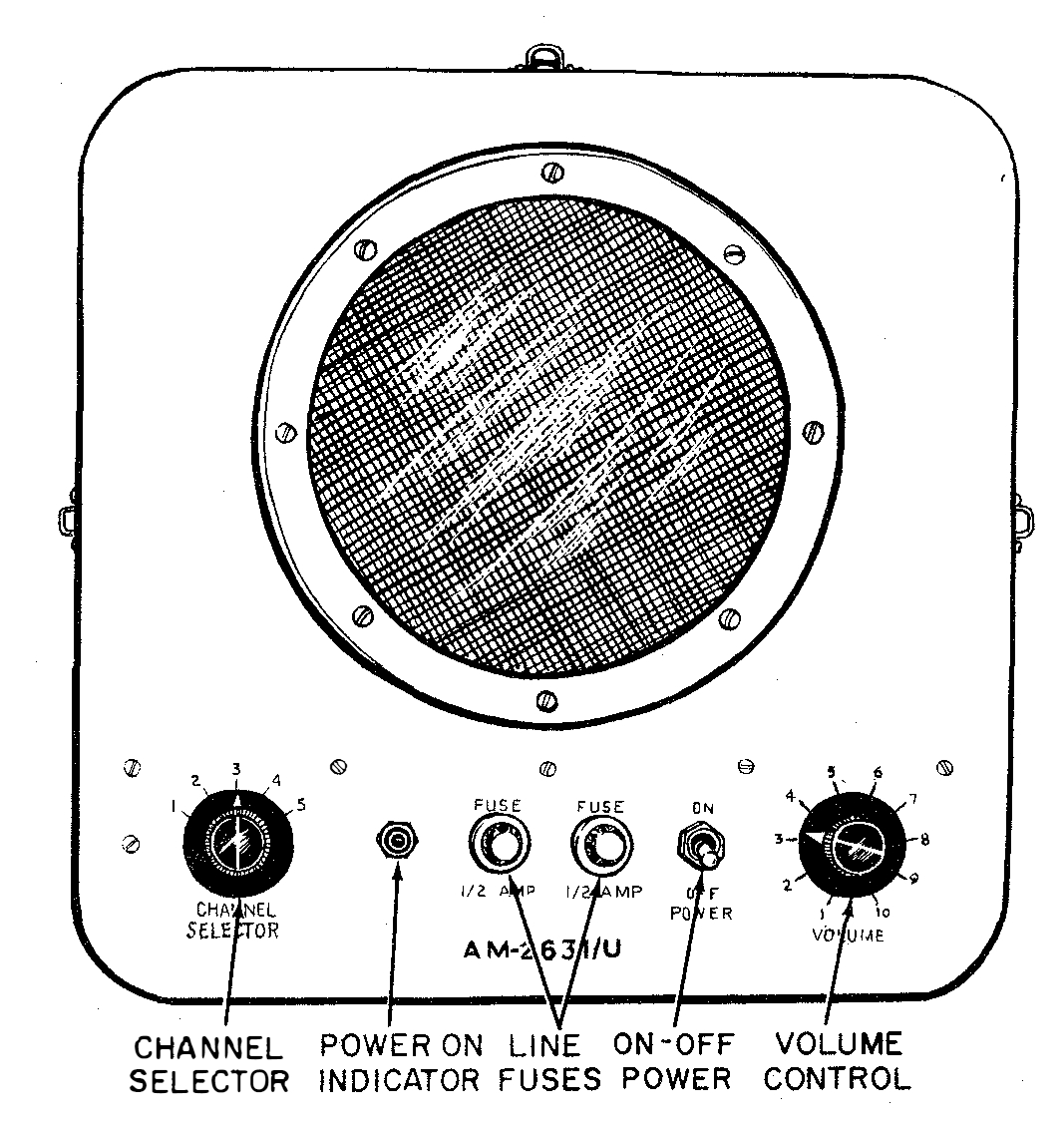
The AM-215( )/U is an audio amplifier unit that amplifies low-level audio signals for reproduction through loudspeakers. As many as five radio receivers and five loudspeakers can be connected to this unit, but only one signal is amplified and reproduced at any one time. The signal to be amplified and reproduced is selected by means of a channel selector switch located on the front of the amplifier unit. Other controls on the unit's front panel are a volume control, a power on-off switch, and a power-on indicating lamp. AM-215B/U, AM-215C/U, AM-215D/U manual - NAVSHIPS 91626 pdf |
|
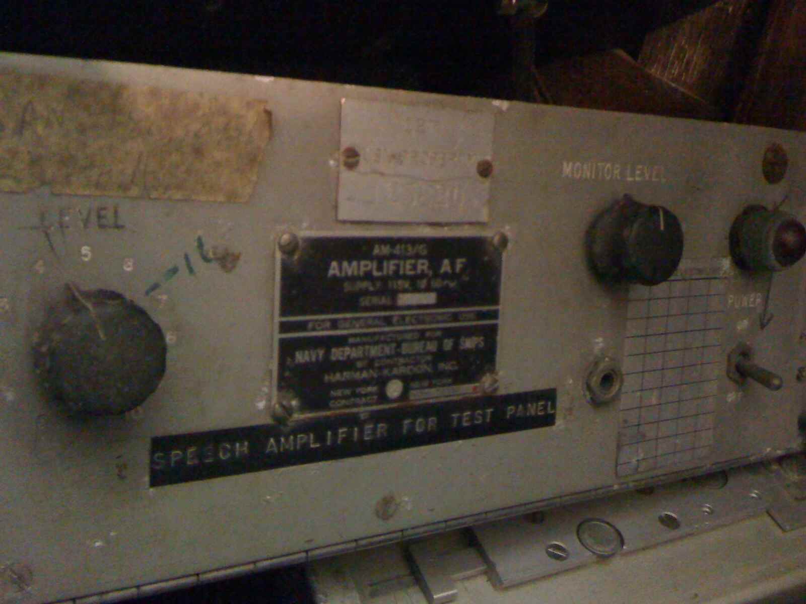
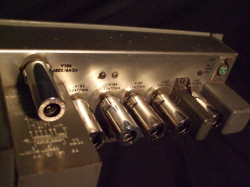
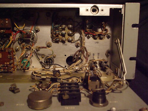
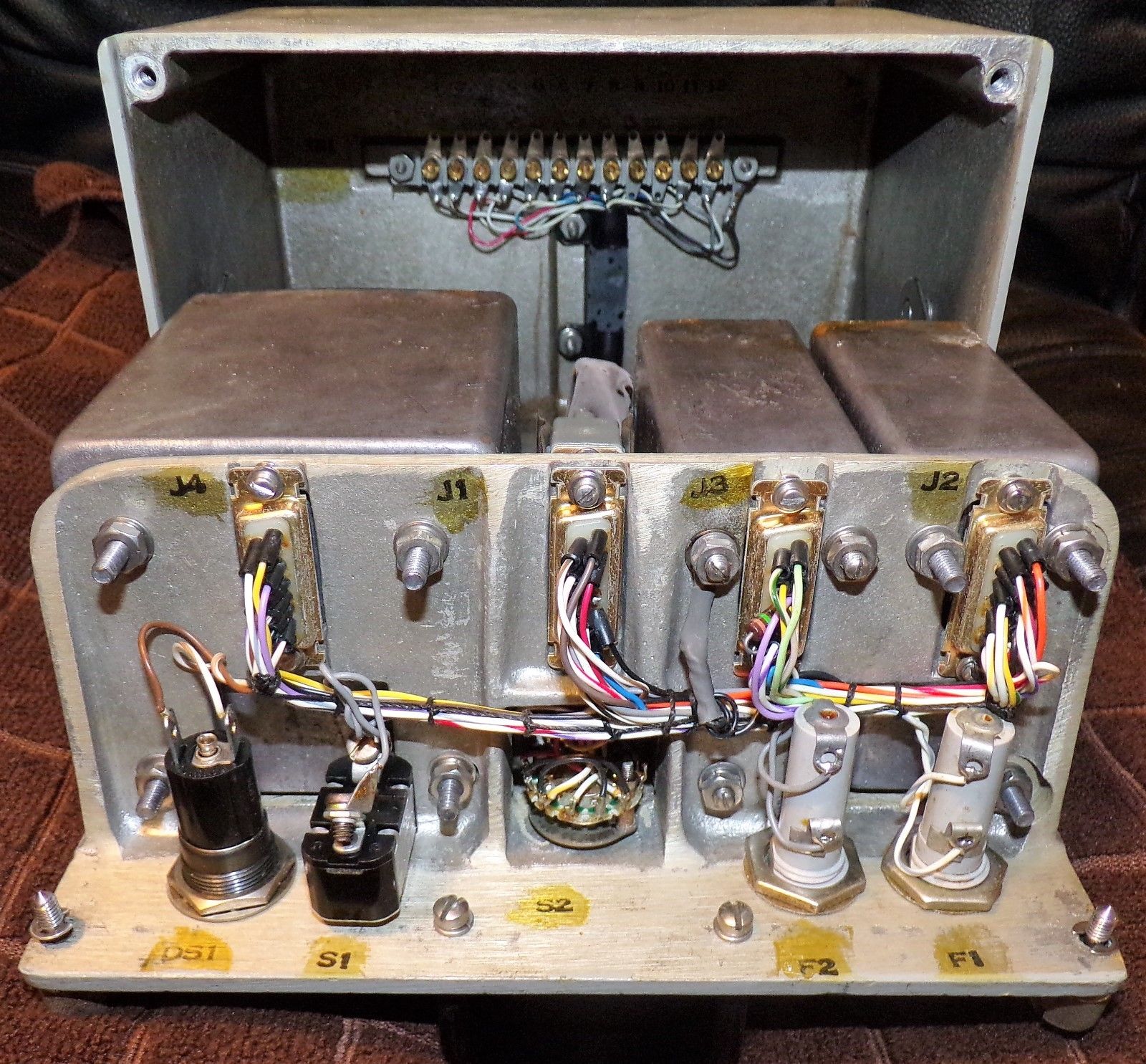
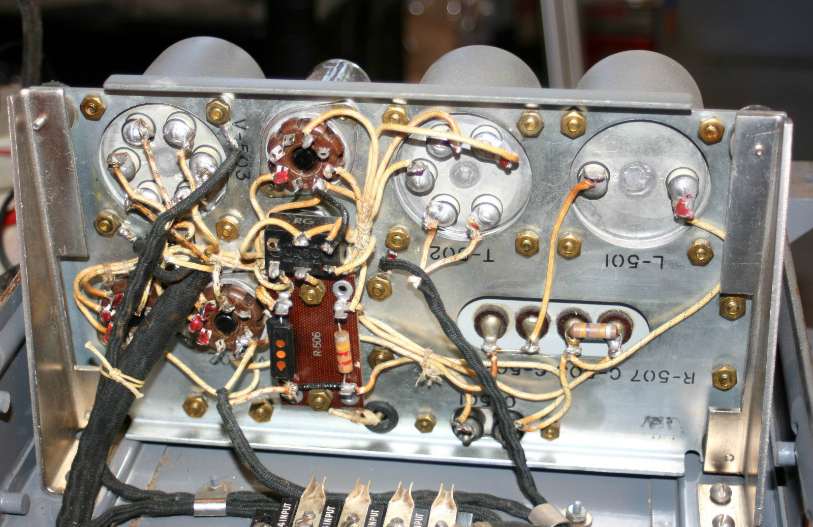
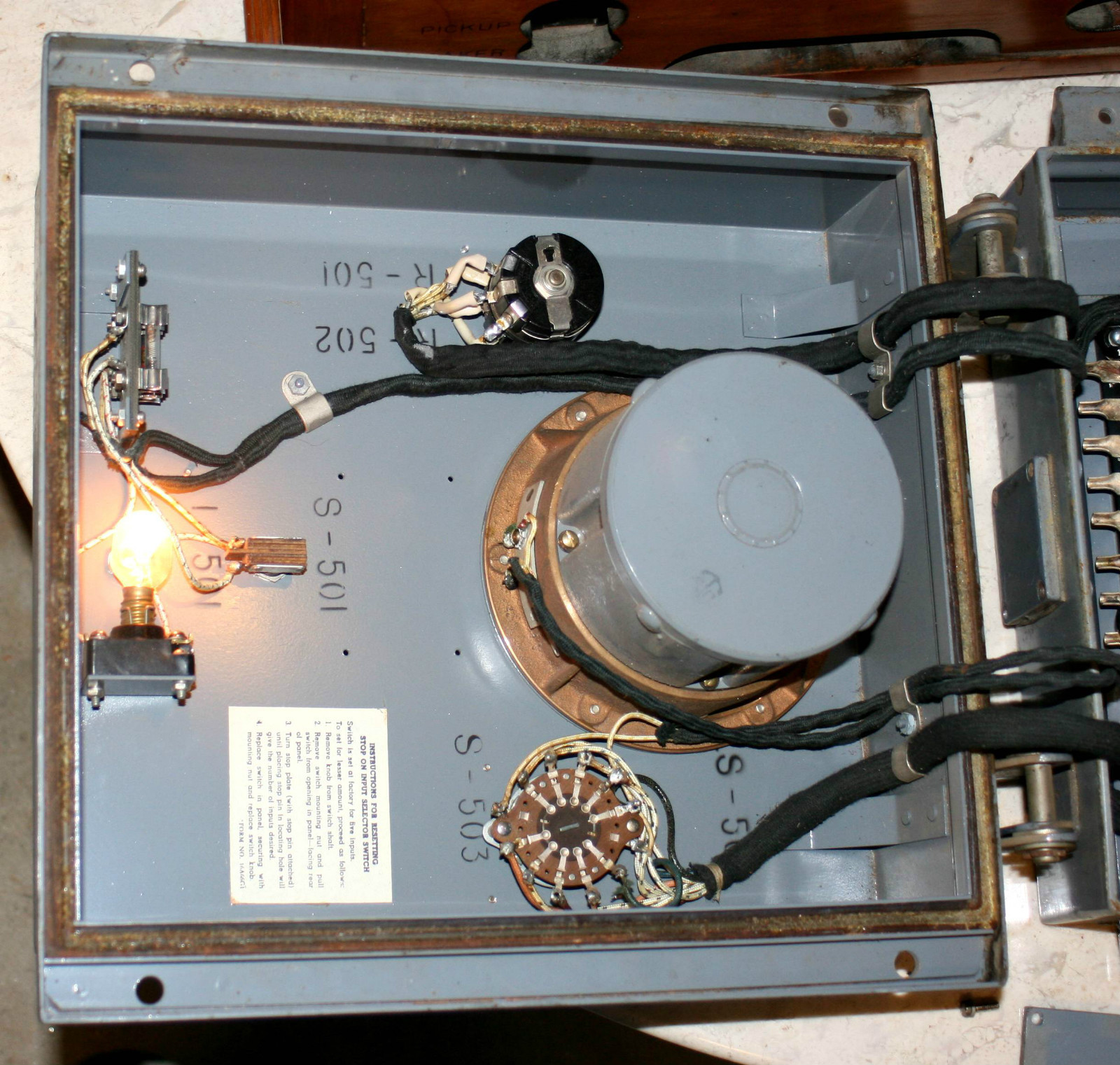
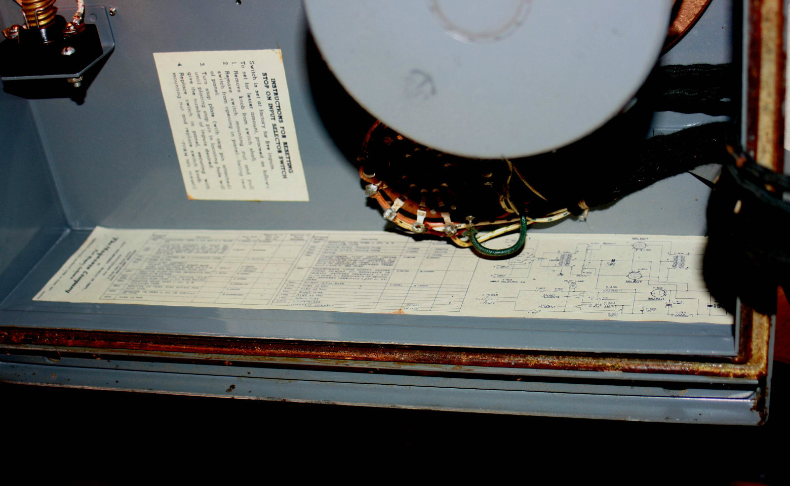
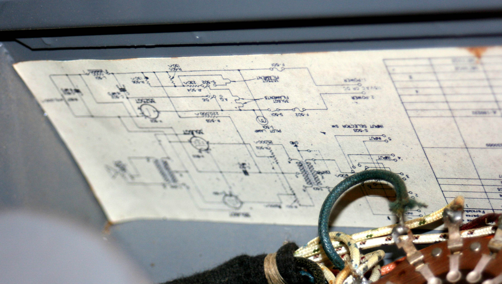
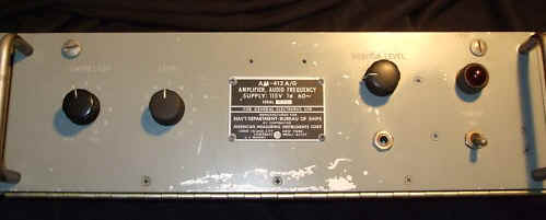
AM-413/G
|
 |
 |
Manuf - Harmon-Kardon AM-413/G Amer. Measuring Instrument - AM-413A/G
|
|
|
 |
 |
|
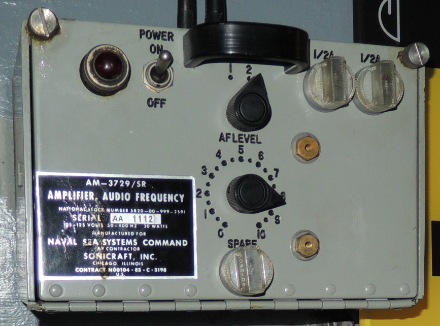
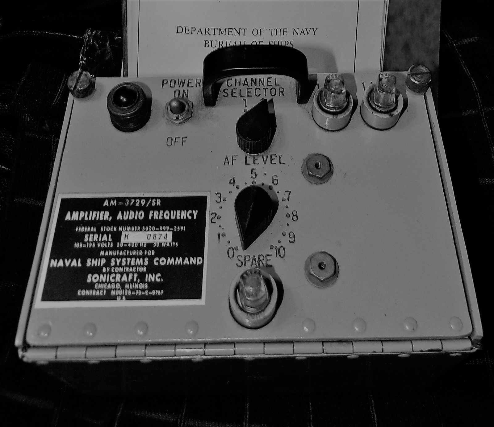
AM-3729/SR audio amp
|
transistorized replacement for AM-215/U - Manual
|
 |
|
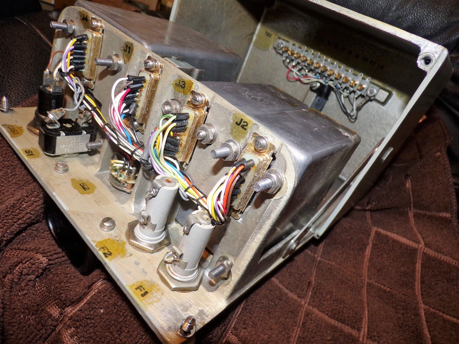
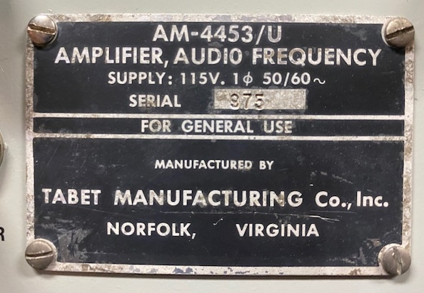
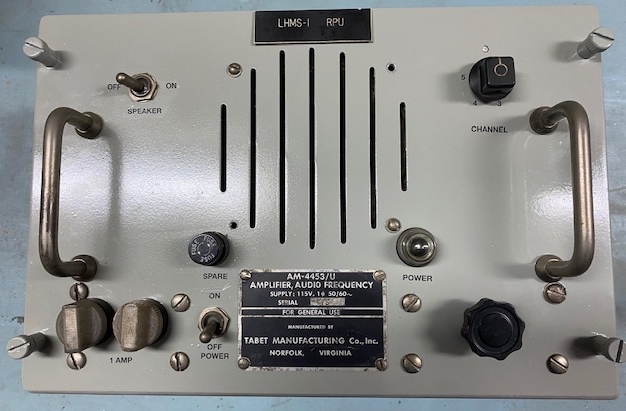
AM-4453/U
|
Speaker-Amp - Specs 5 input, 10 watt, transistorized Manual Photos and manual thanks to Daniel K6YIC
|
 |
|
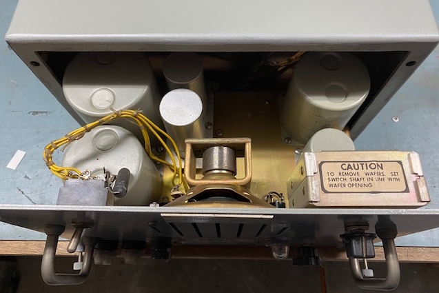
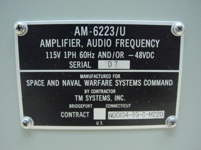
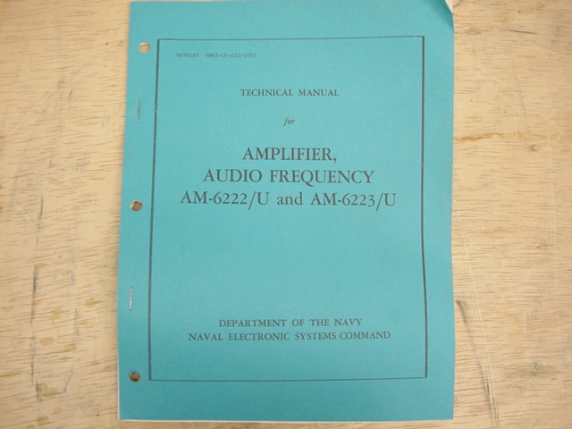
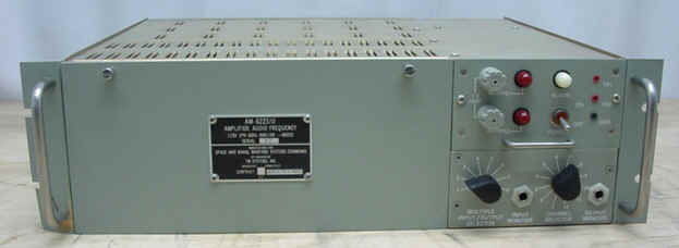
AM-6222/U
|
 |
 |
|
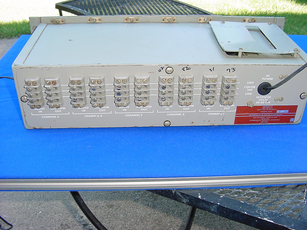
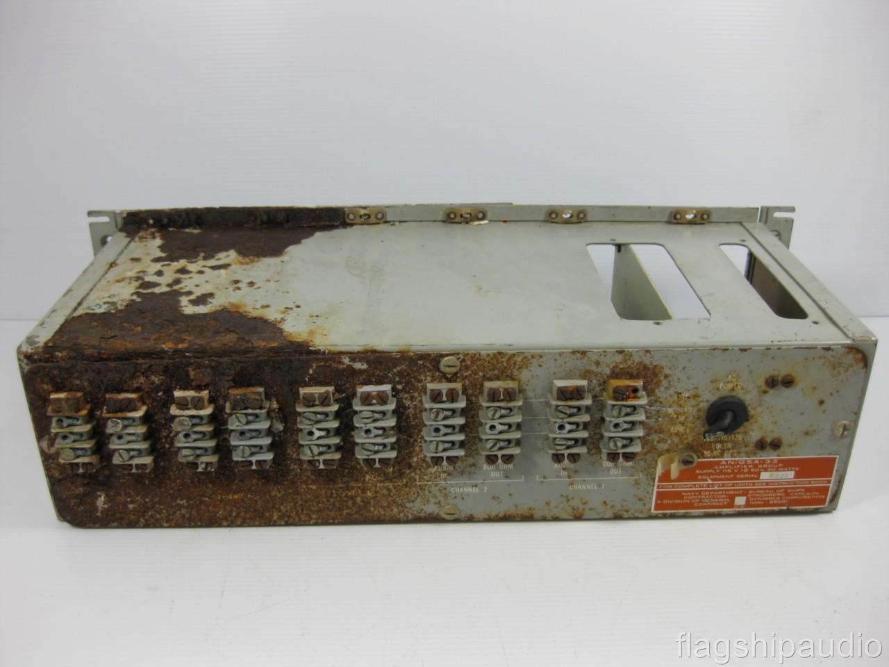
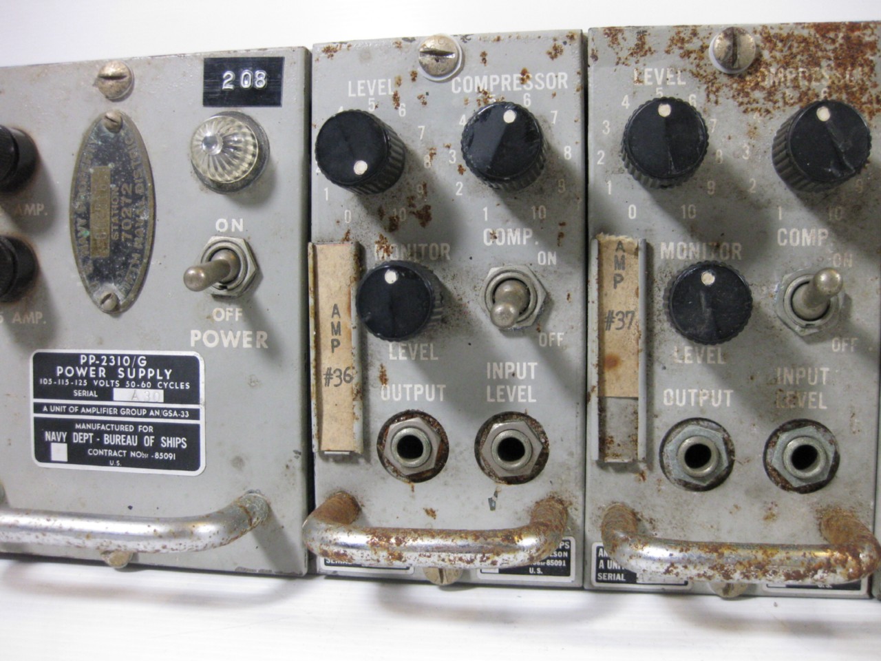
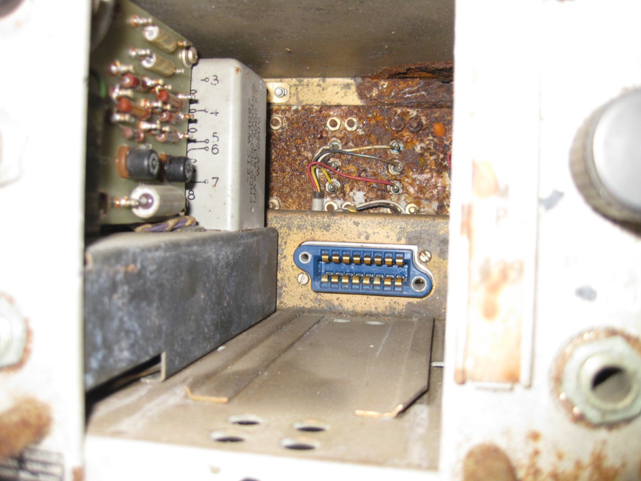
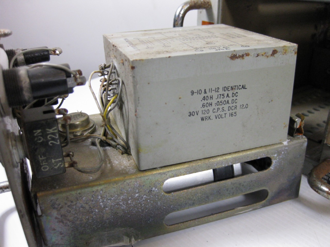
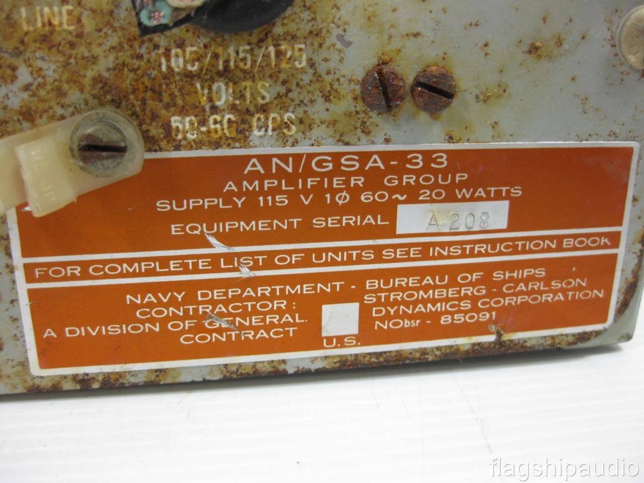
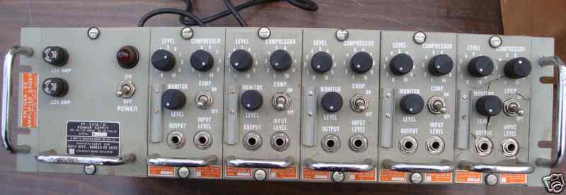
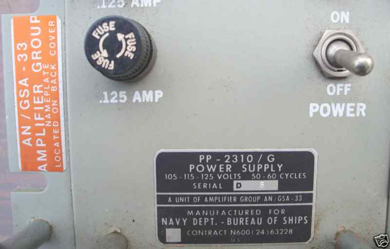
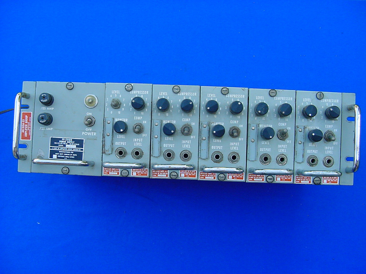
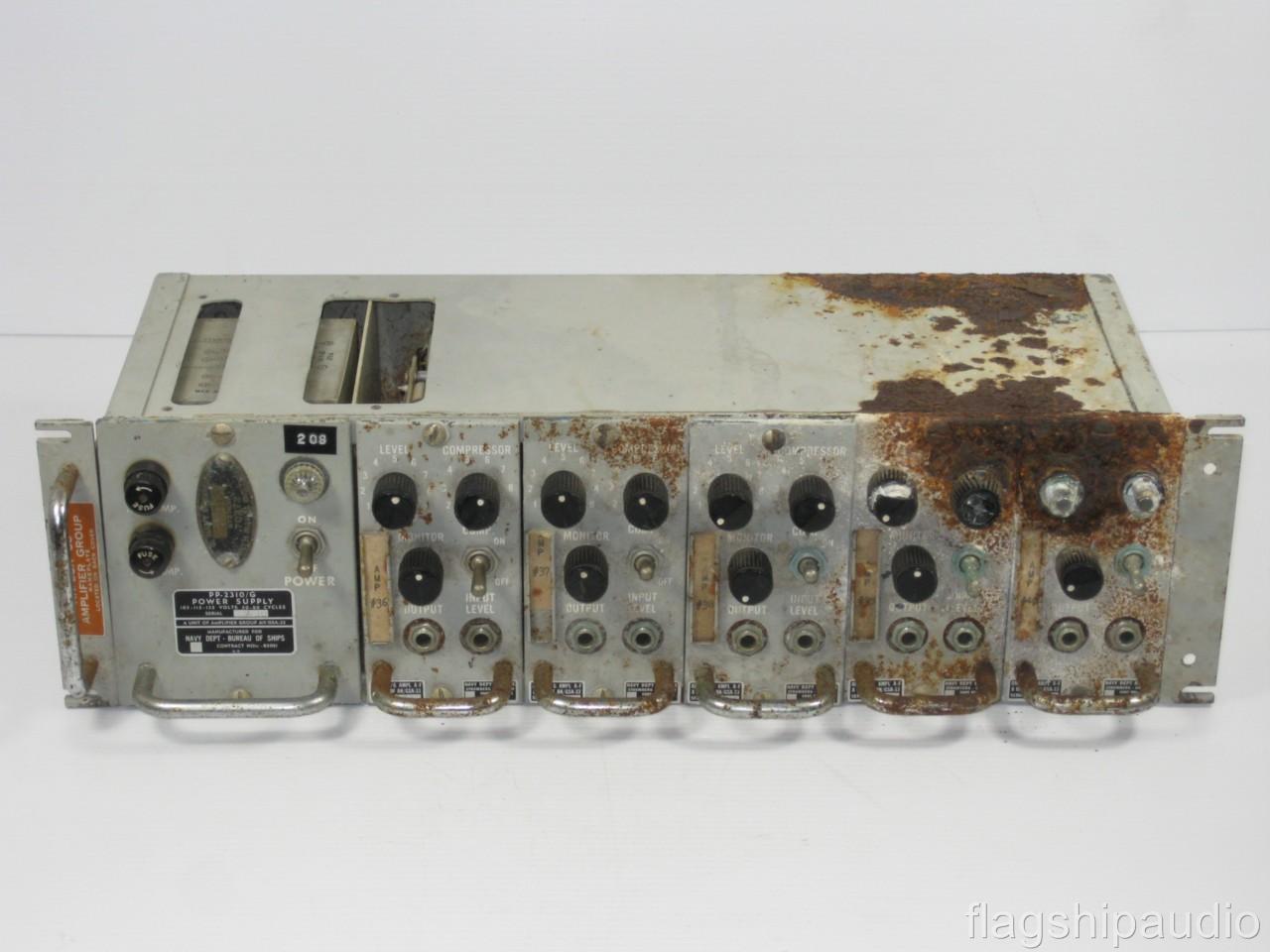
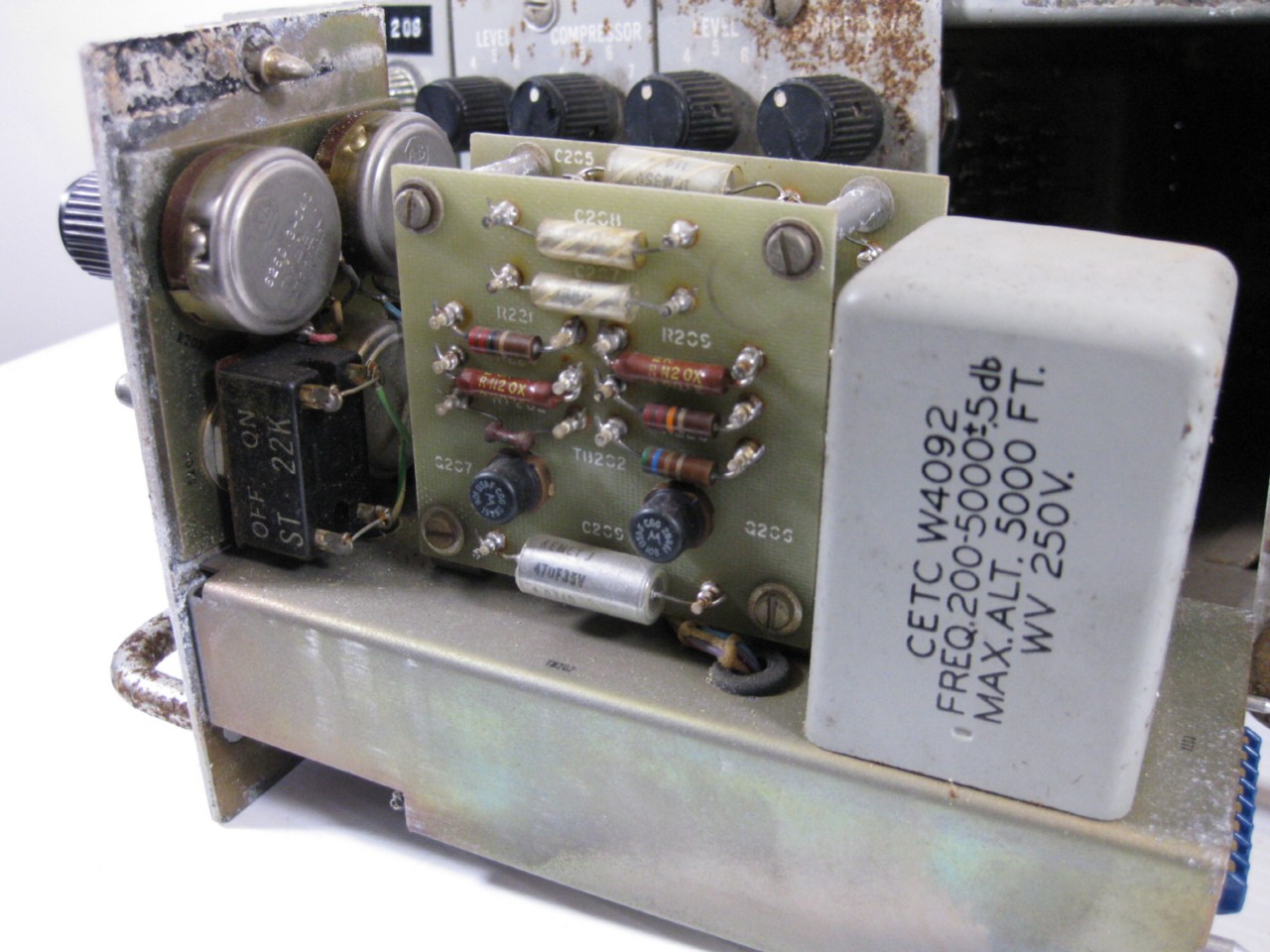
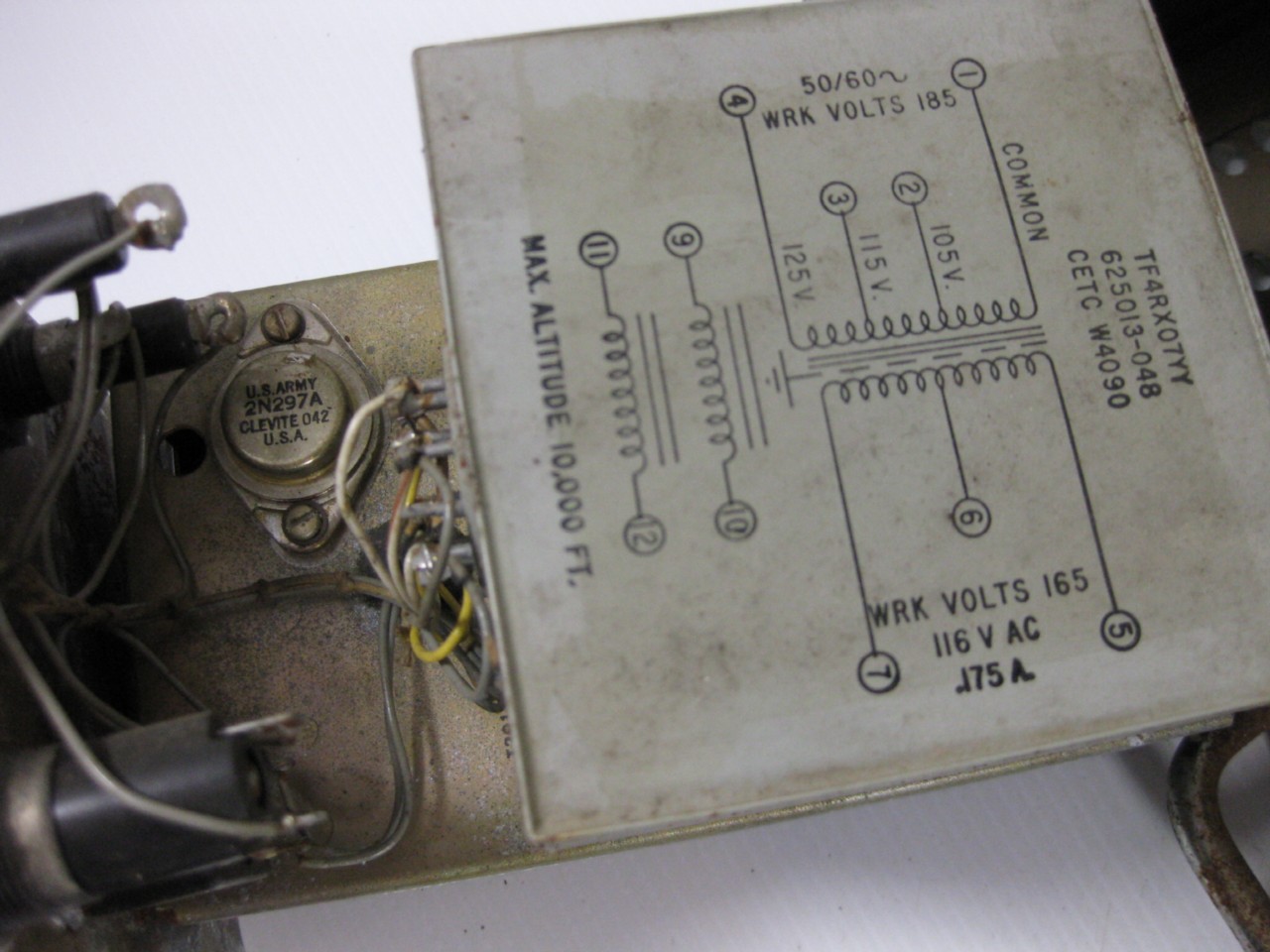
AN/GSA-33
|
Amplifier Group 5 channel compressor AM-1910/G amplifiers |
|
Manuf Melcor
NAVSHIPS 93433 Please send me email if you have a manual I can borrow/buy |
|
|

|
|
-- |
|
|
|

|
|
|
|

|
|
-- |
|
|
|
|
-- |
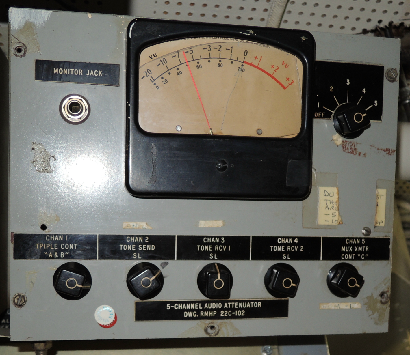
RMHP 22C-102
|
shipyard built item aboard USS Midway |
-- | -- |
| -- | |||
Communications Loudspeakers & Amplifier-Loudspeakers |
|||
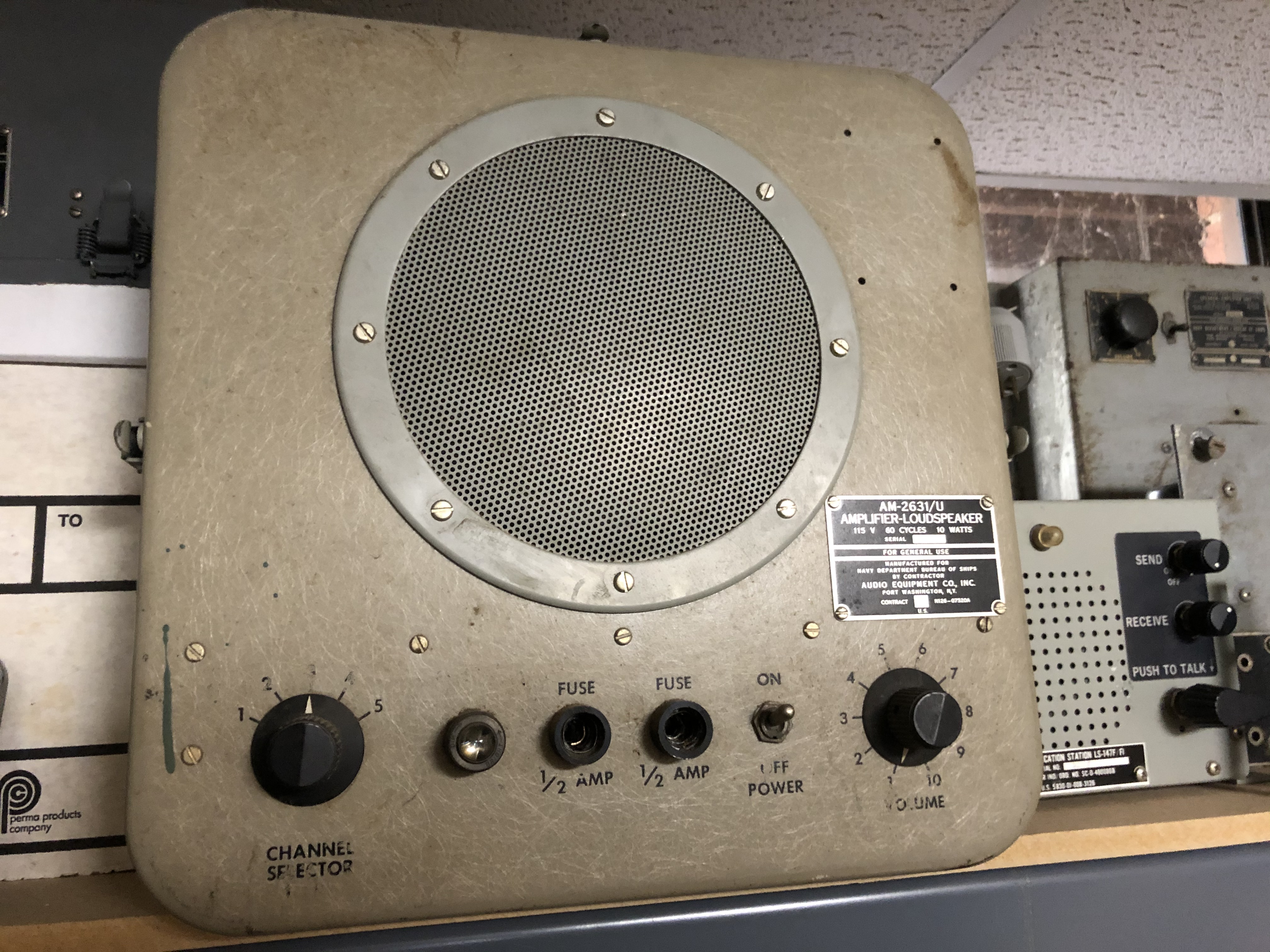
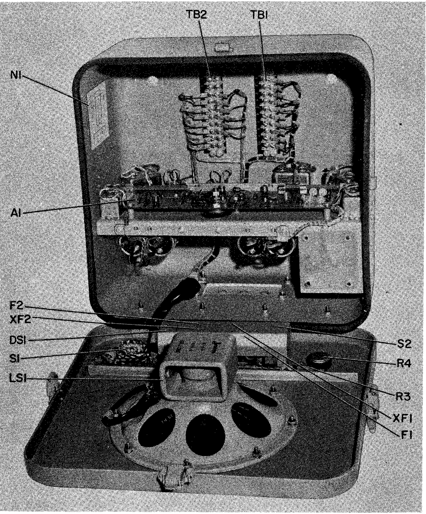
AM-2631/U Amplifier-Loudspeakergeneral purpose speaker with built-in audio amp. Five input channels, 5
watts. |
|
|
|
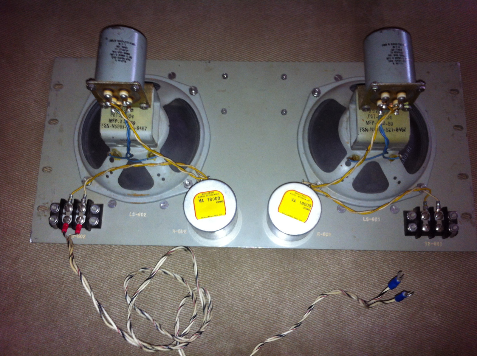
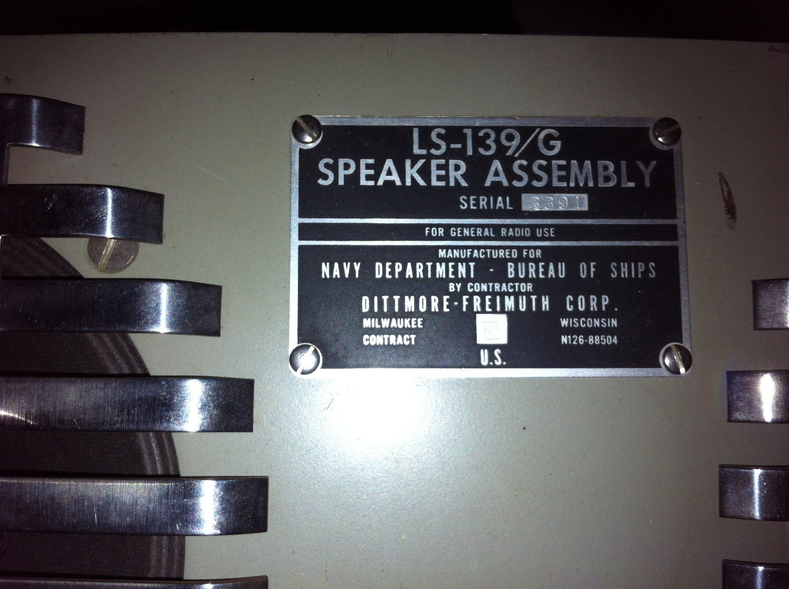
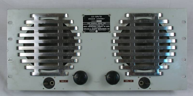
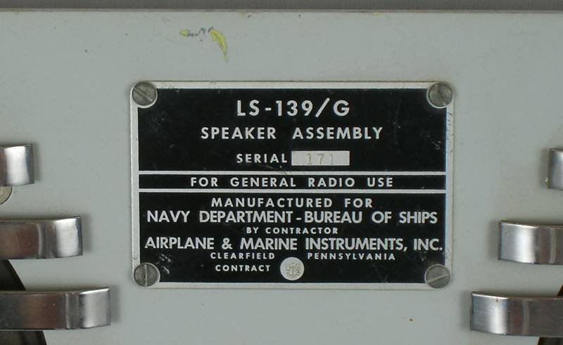
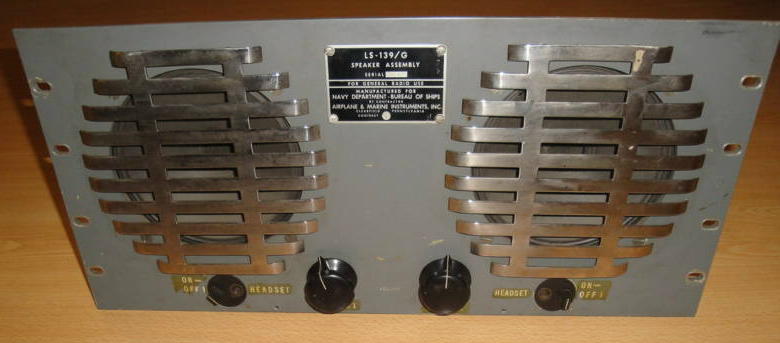
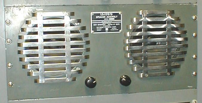
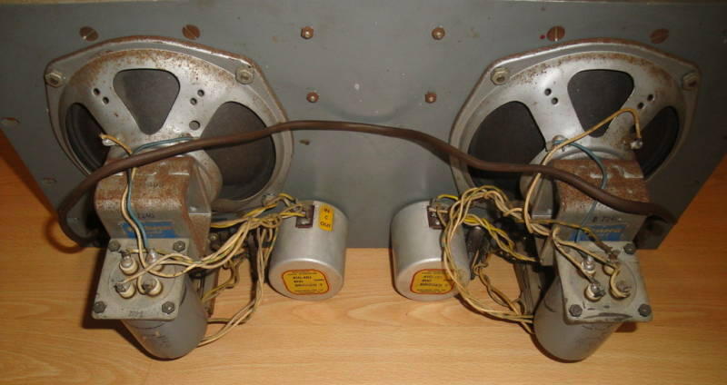
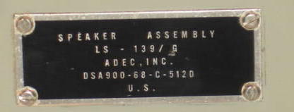
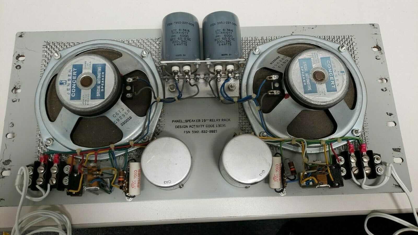
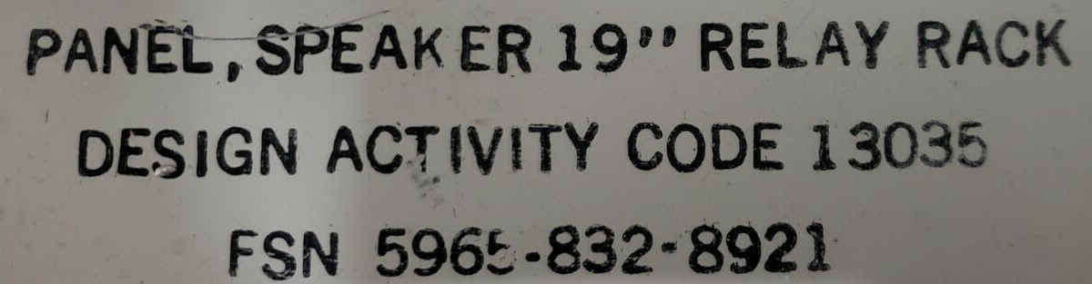
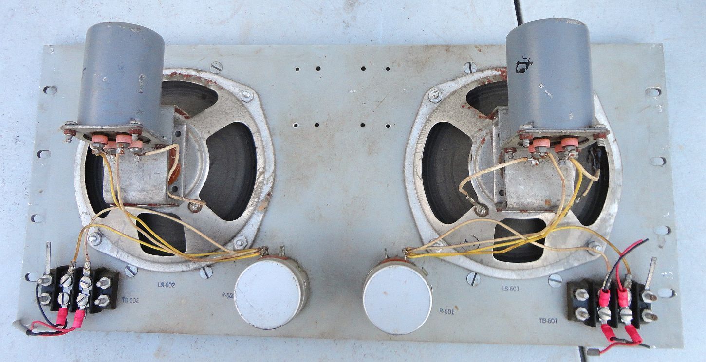
LS-139/GRack mount twin speaker
|
Version without phone jacks Manuf Westlab & others  Version with phone jacks |
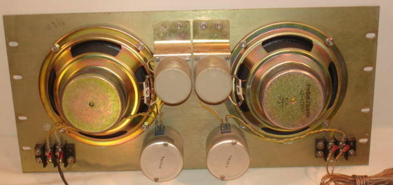
Another version (DSA, not USN - manuf Adek) 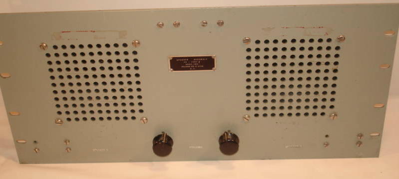
|
Another version (not USN)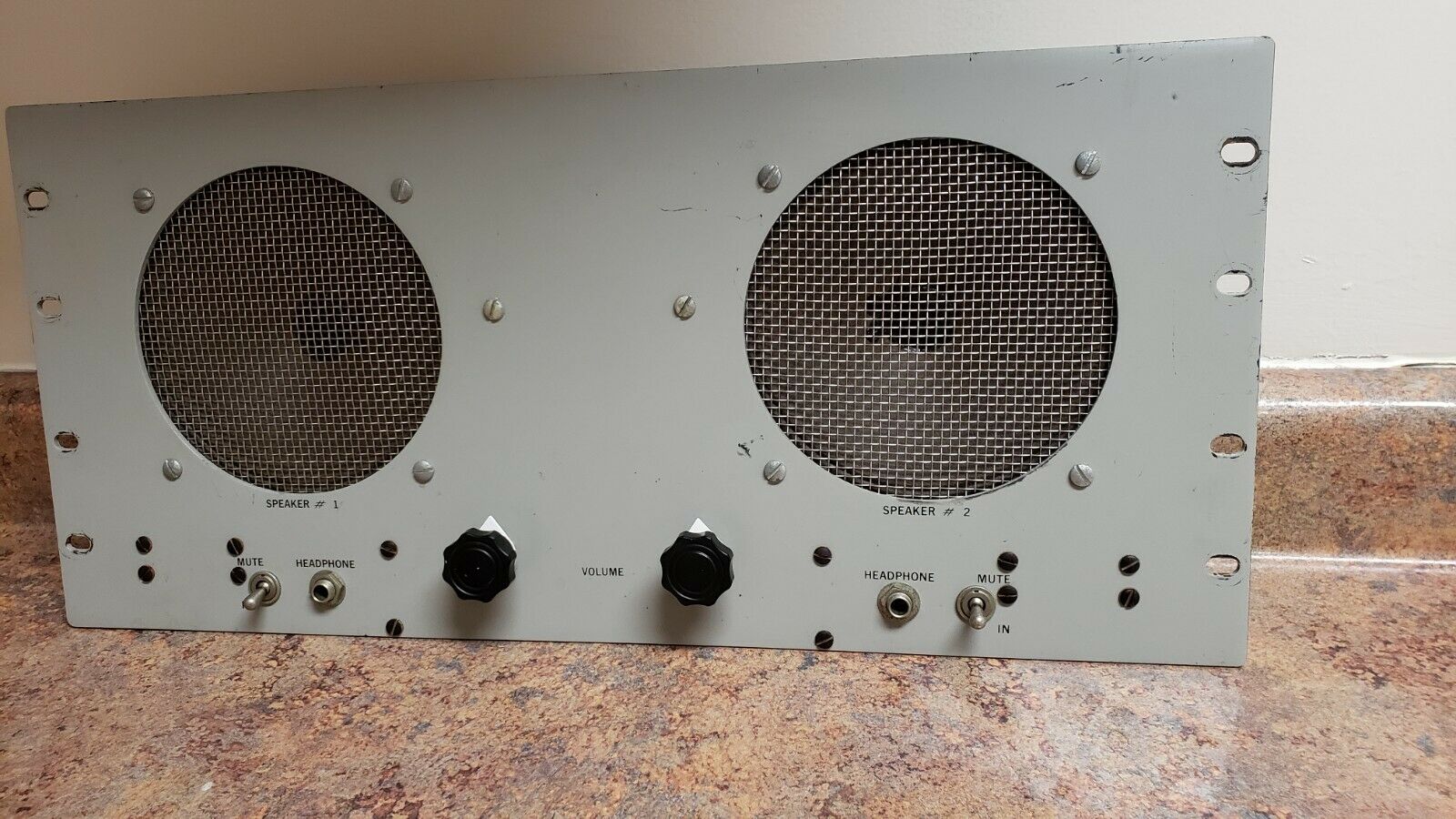
|

|
|
|
NAVSHIPS 93095 |
|
|
|
|
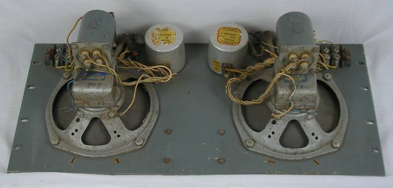
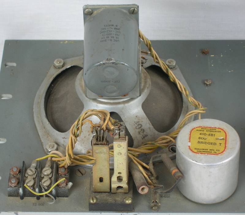
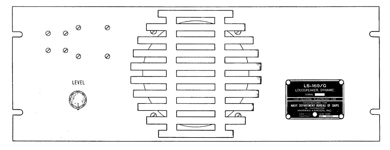
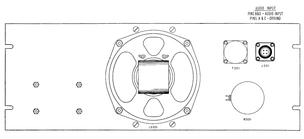
LS-169/Gmanual download (includes AM-413/G) |
A single-speaker version of the LS-139/G |
|
|
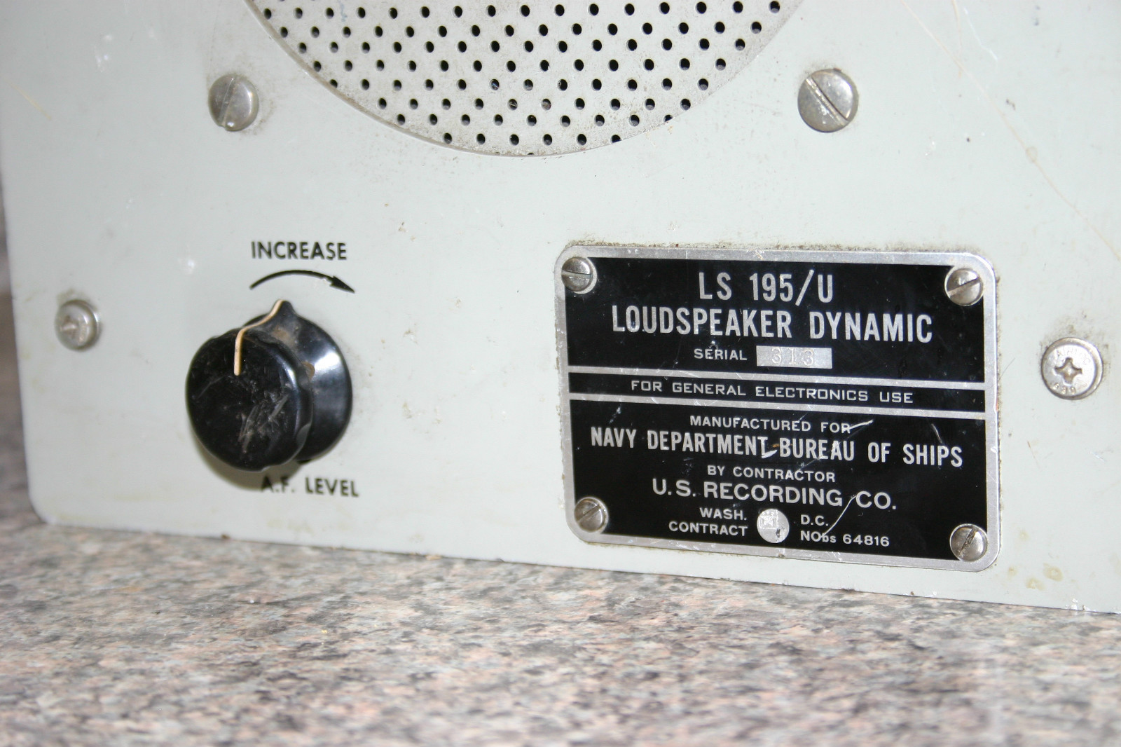
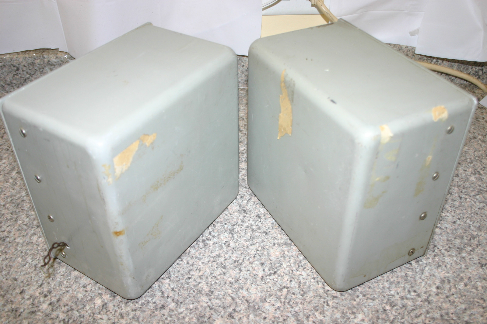
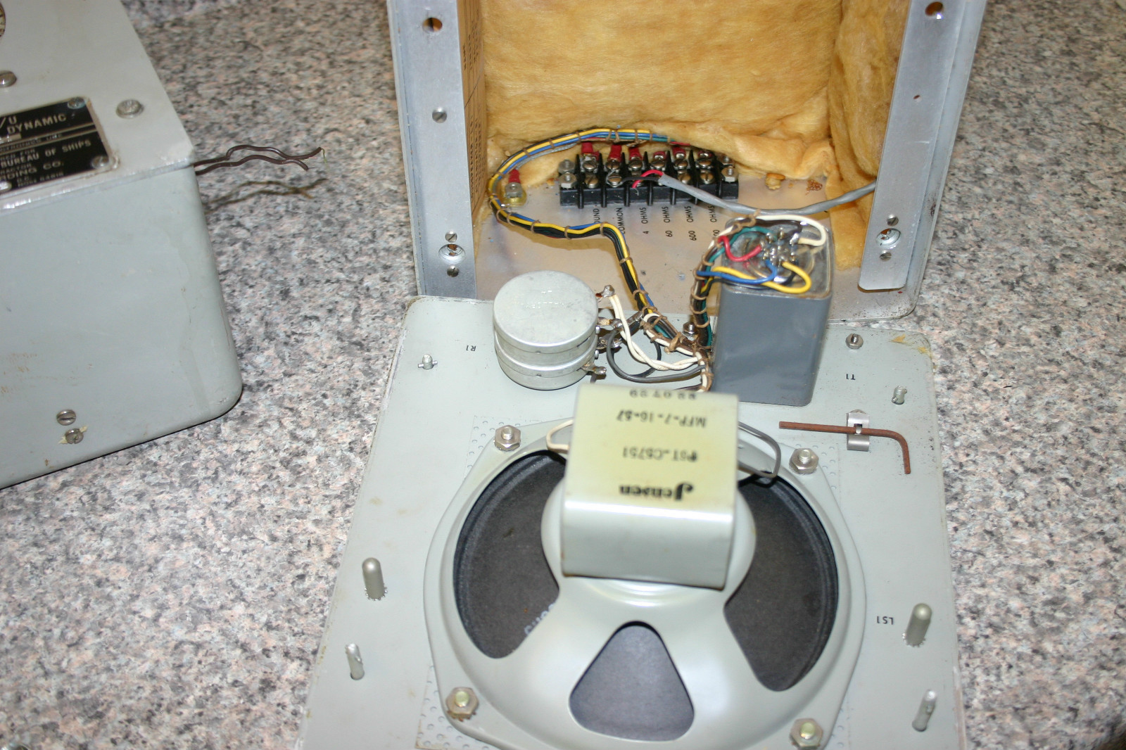
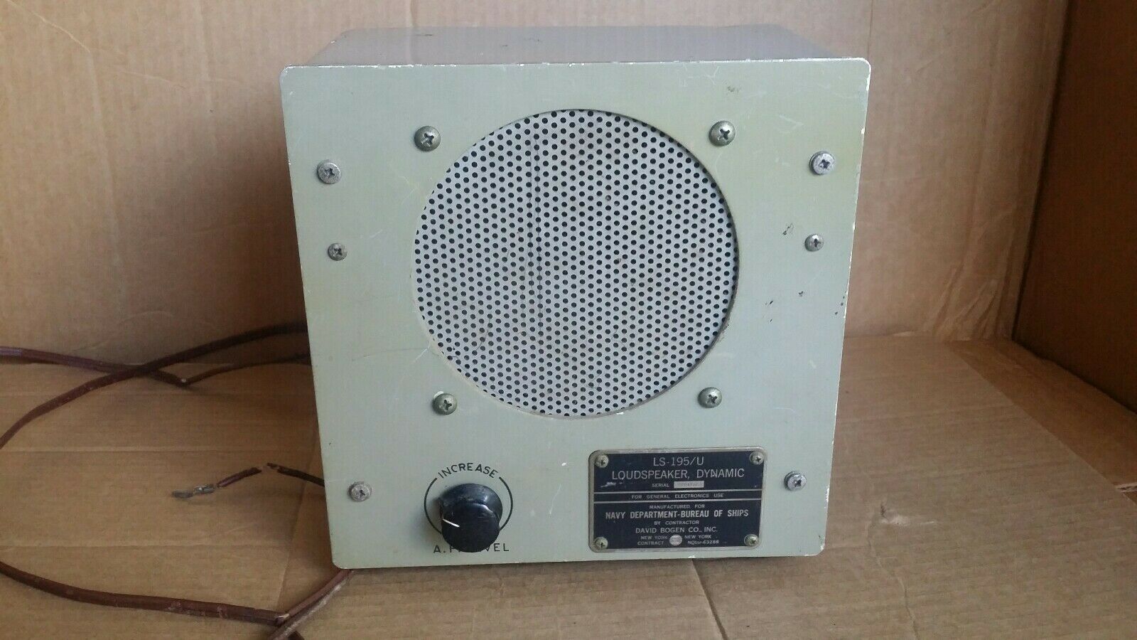
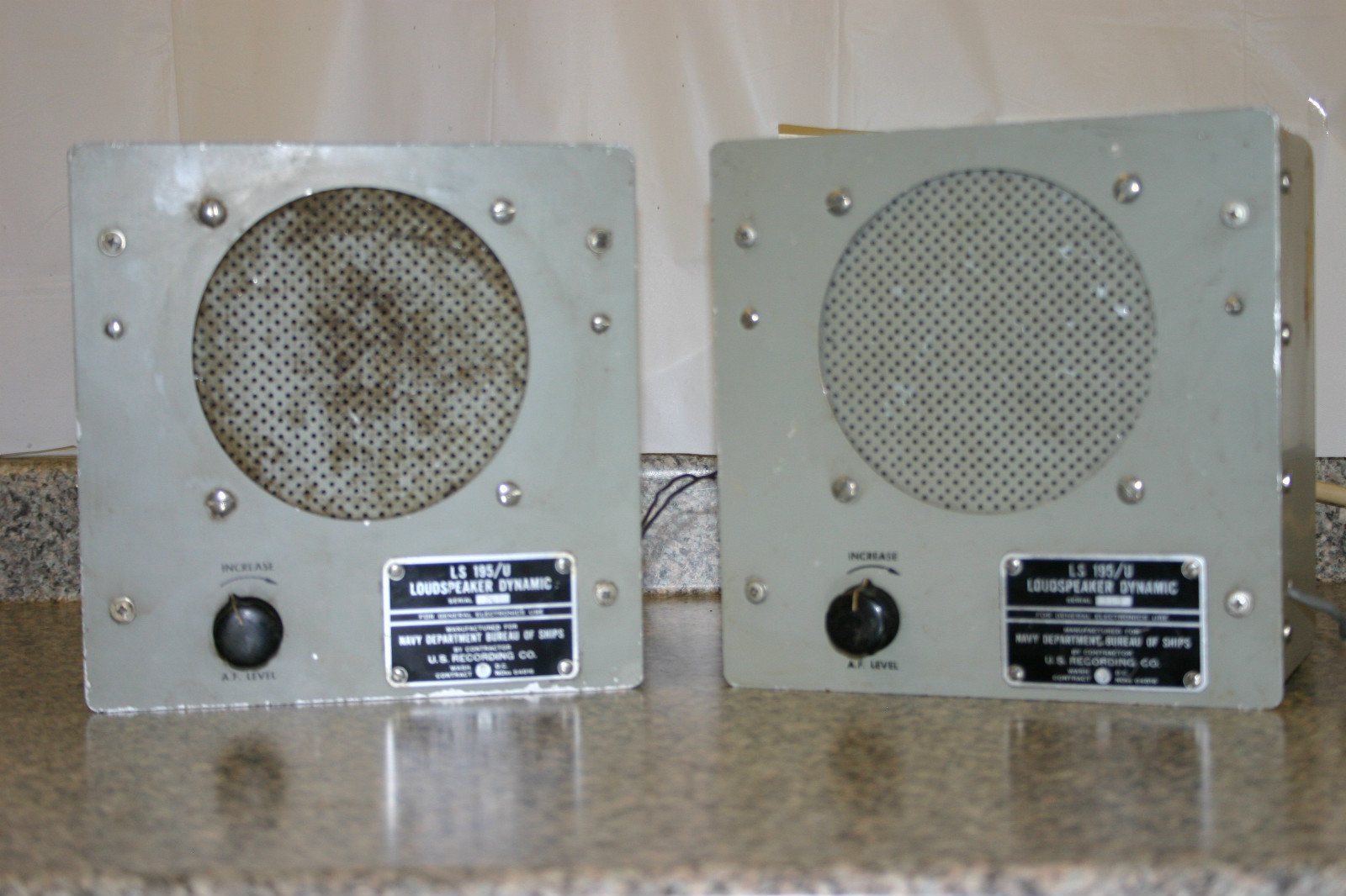
LS-195/U
|
A general-purpose communication loudspeaker is the LS-195/U. Like the NT-49546, this unit is used mainly for monitoring voice channels. Unlike the NT-49546, however, the unit cannot withstand prolonged exposure to the weather; it is designed for installation in protected areas only. In addition, it has a front panel volume control and is transportable, whereas the NT-49546 has a preset, covered volume control and is mounted permanently. |
||
|
|
|

|
 |
 |
 |
== |
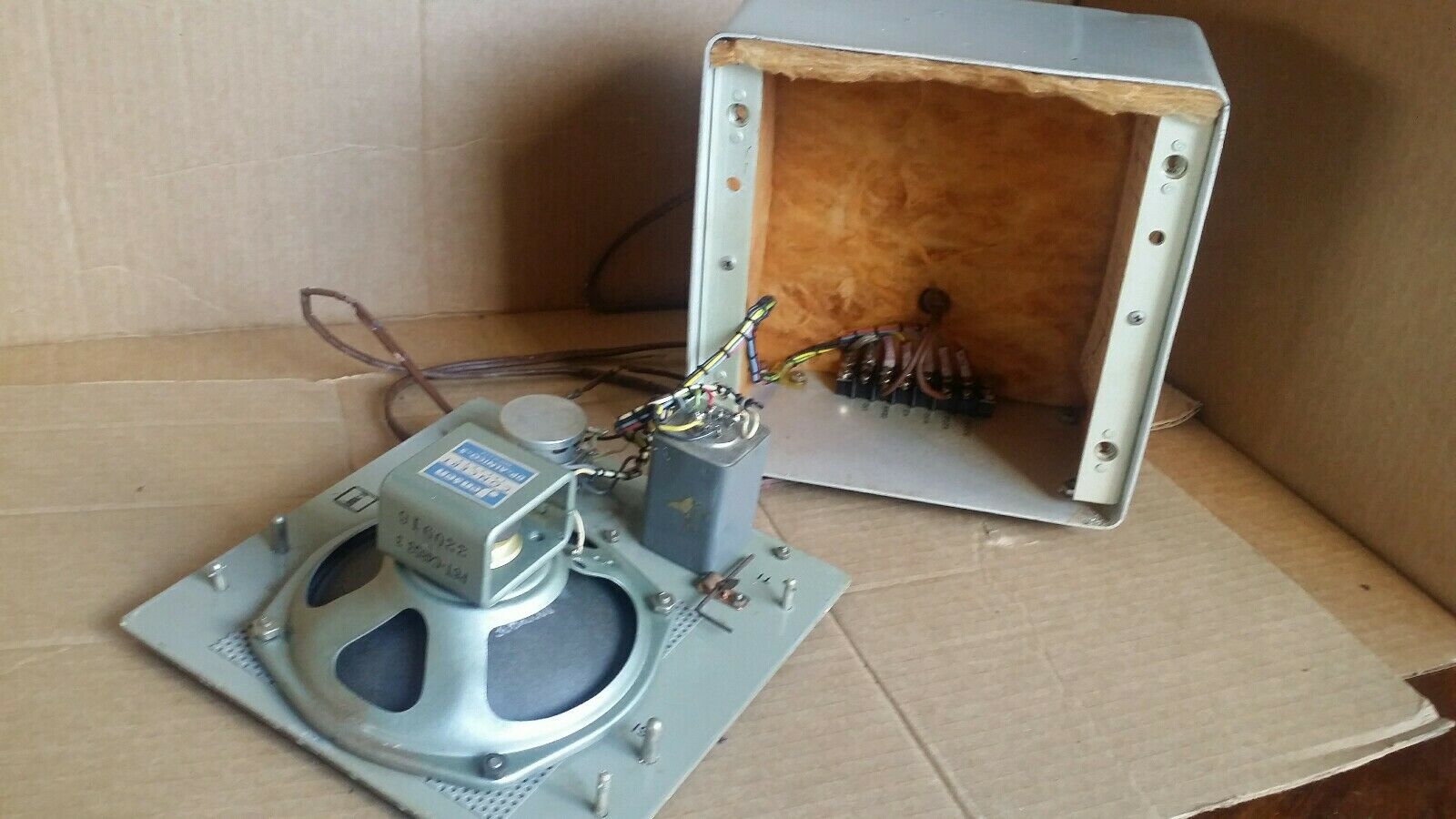
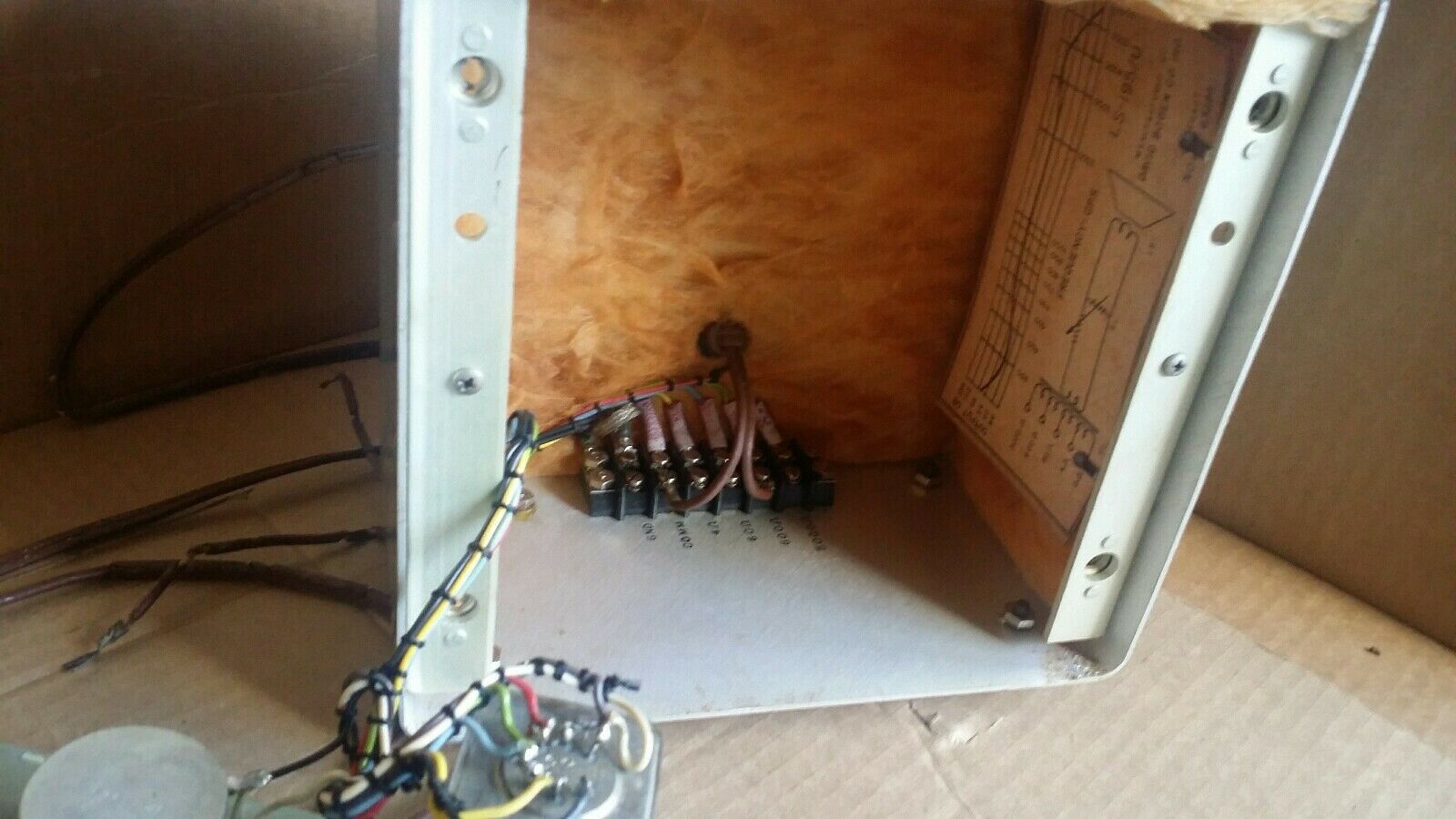
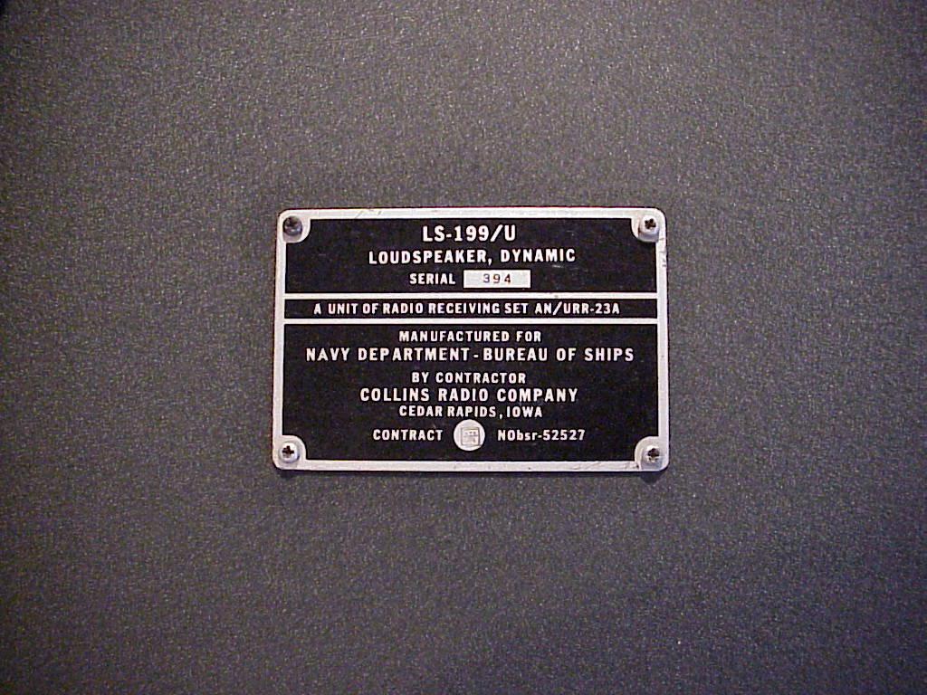
LS-199/U (for AN/URR-23A)
|
 |
LS-228/U (for AN/URR-39)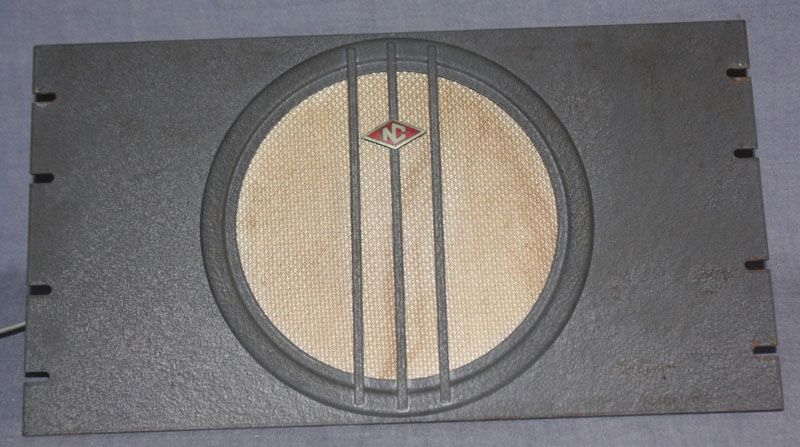 |
 |
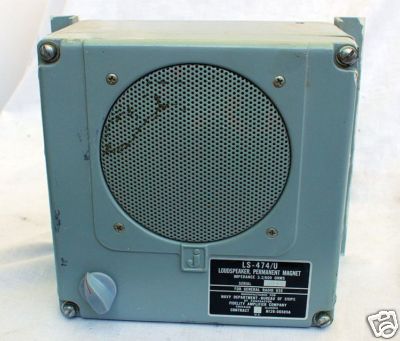
LS-474/U
|
 |
Manuf Fidelity Amplifier
|
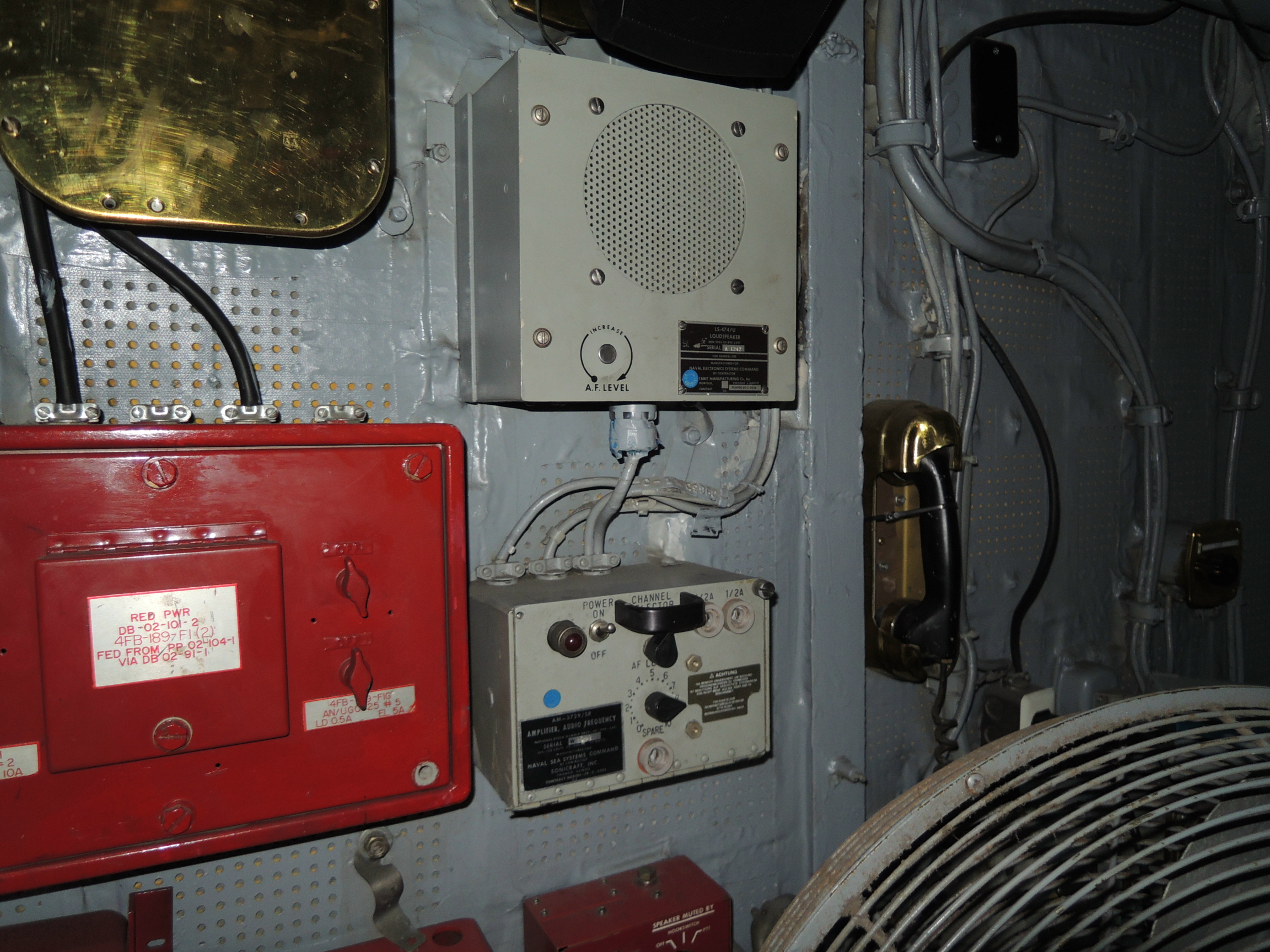 LS-474/U + AM-3729/SR amplifier aboard USS Midway |
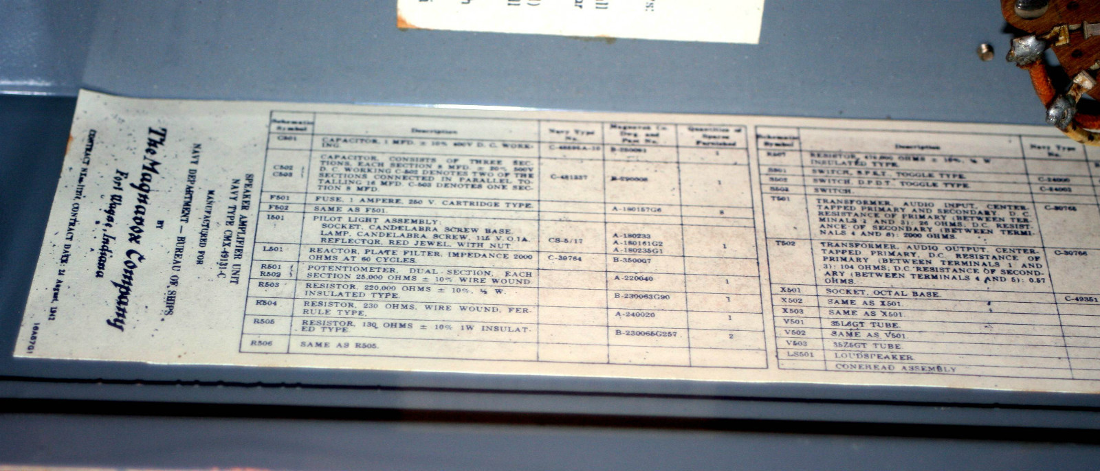
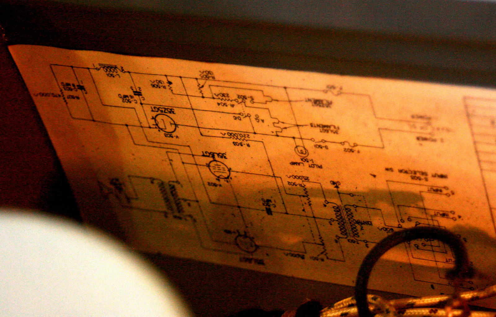
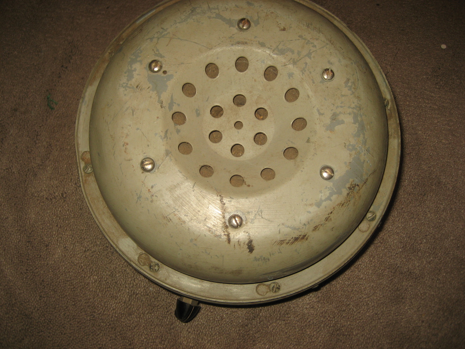
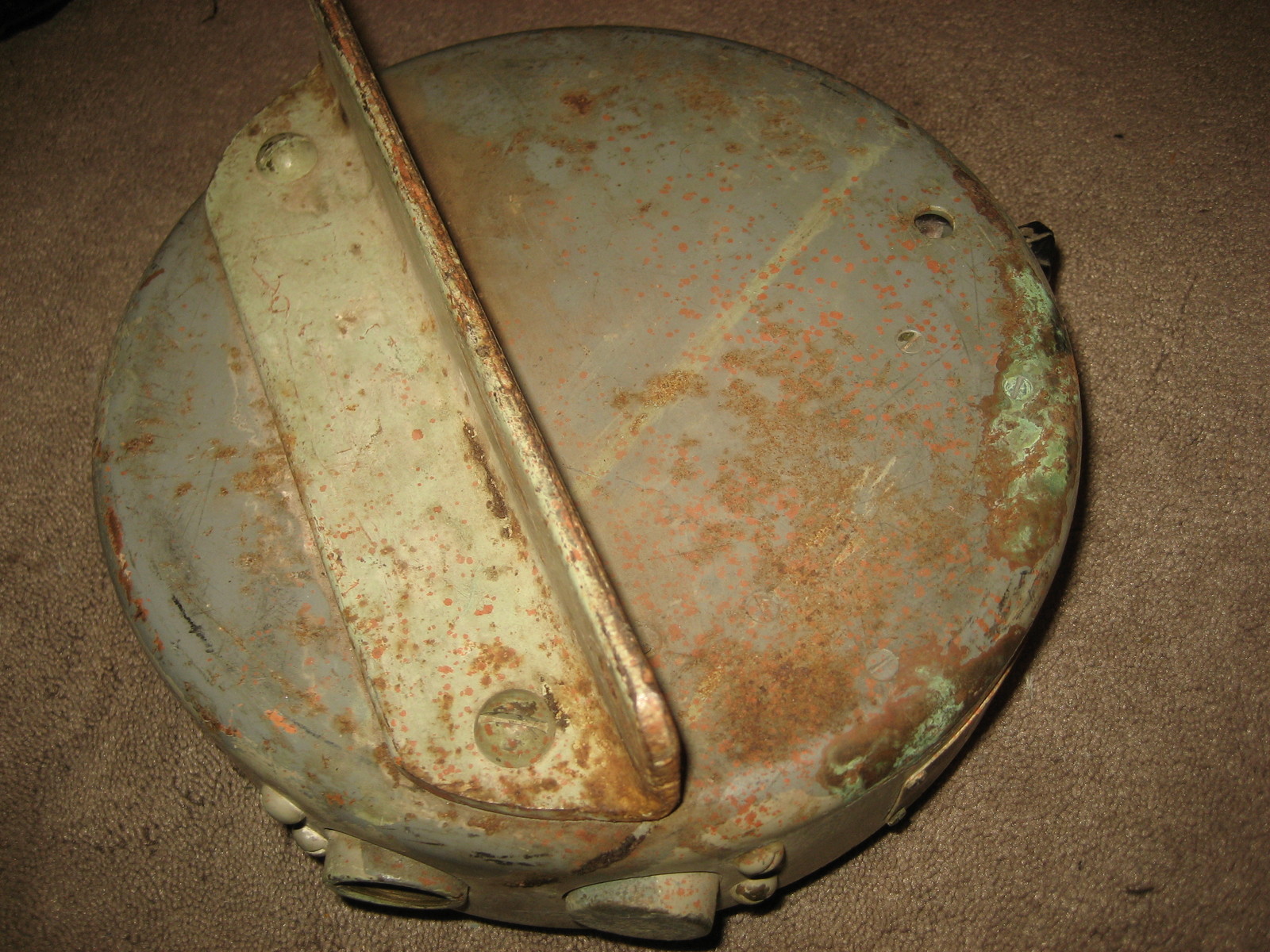
CMX-49131 amplifier-loudspeaker
|
Information -
specs
|
Manuf Magnavox
|
|
|
|
|
|
|
|
== | == |
CHC-49154 (for RBG) |
Photo | 8" permanent magnet speaker with matching transformer (5000 ohm input) | == |
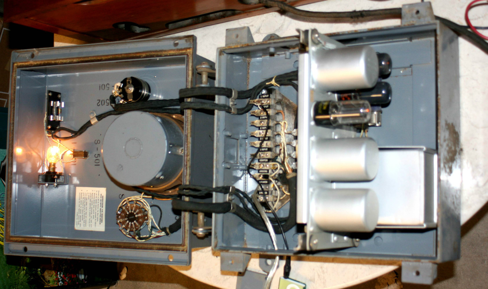
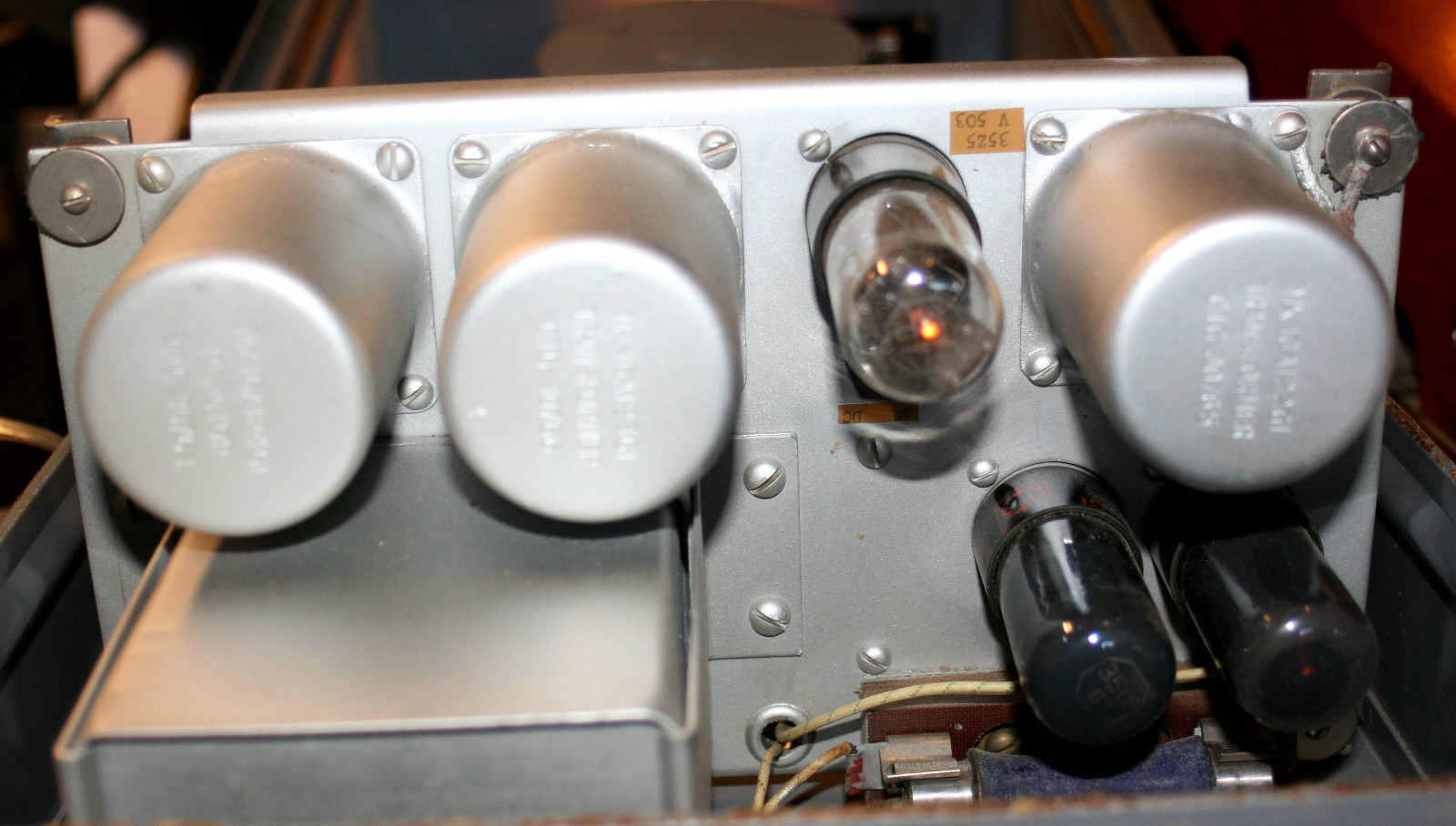
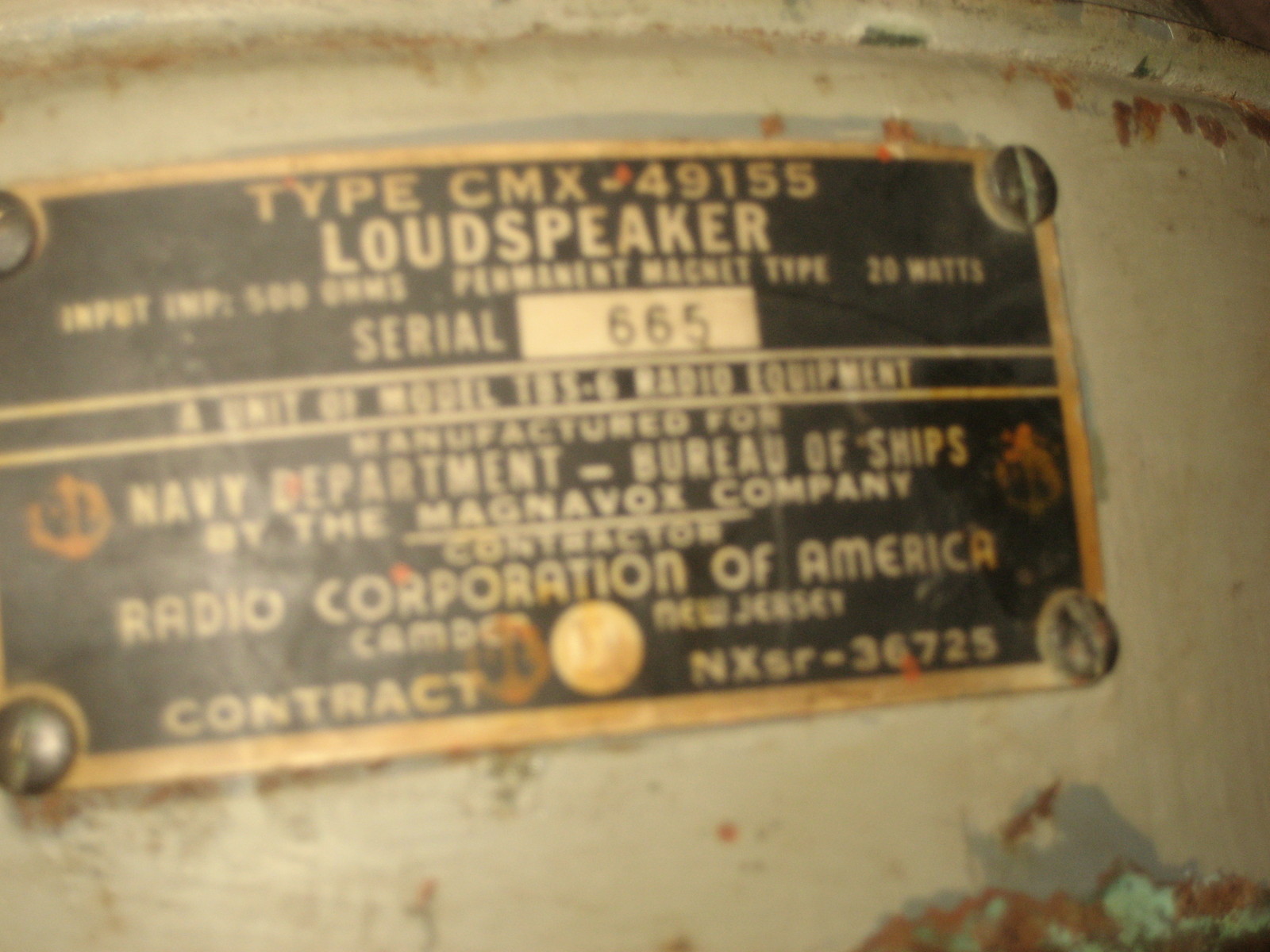
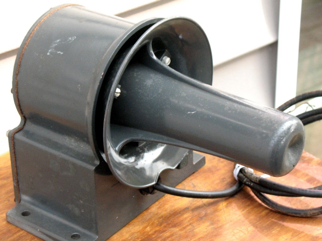
CMX-49155 (for TBS)
|
|
|
== |
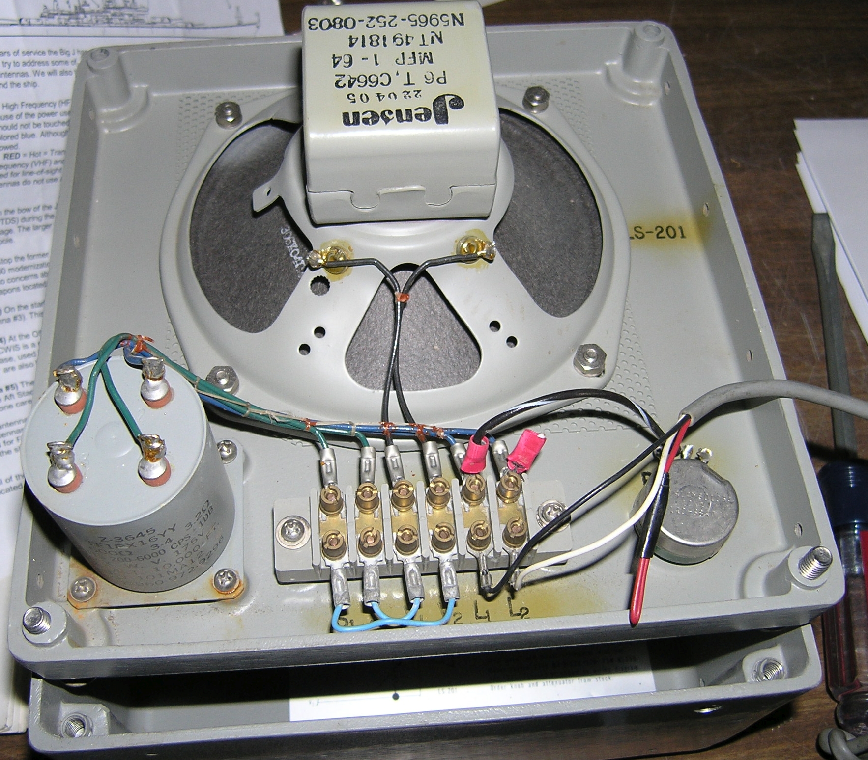
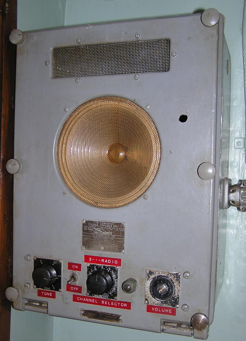
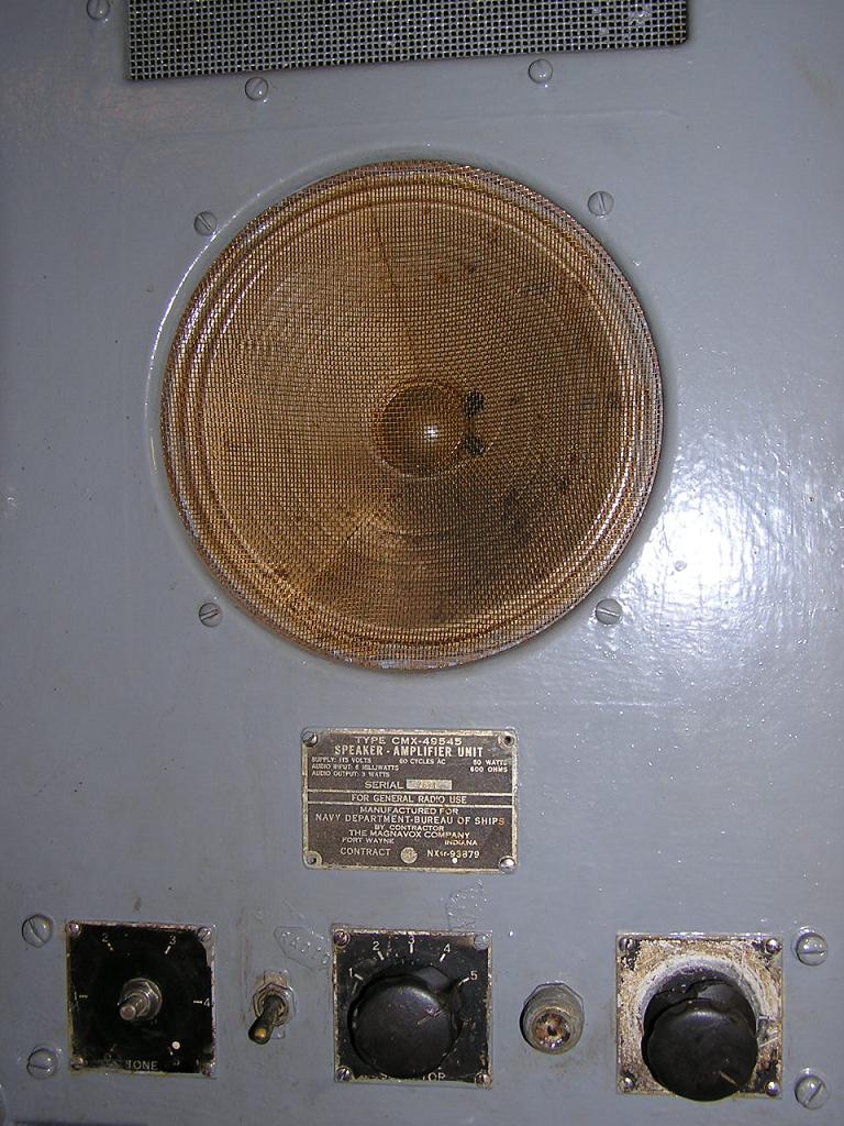
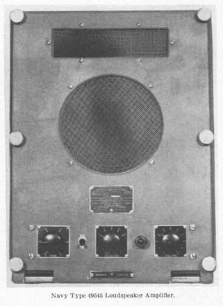
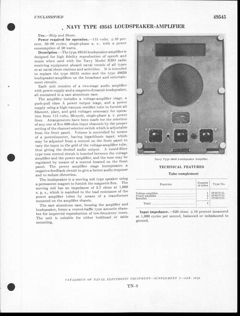
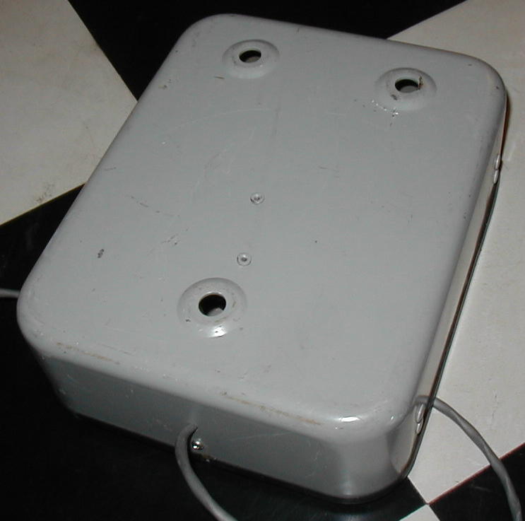
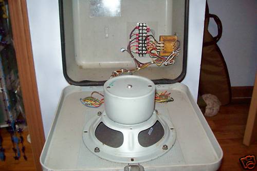
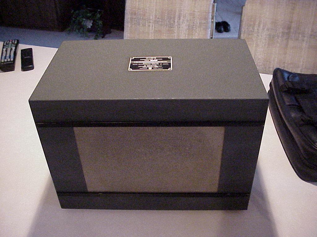
CMX-49545 amplifier-loudspeaker
|
The Navy type 49545 amplifier-speaker unit is a
combination audio amplifier and loudspeaker assembly. Its reproduction
qualities are considered good. Aboard most ships, it is installed in
berthing and messing compartments as an entertainment loudspeaker. Manual NAVSHIPS 900,853 download |
||
 |
 |
 |
 |
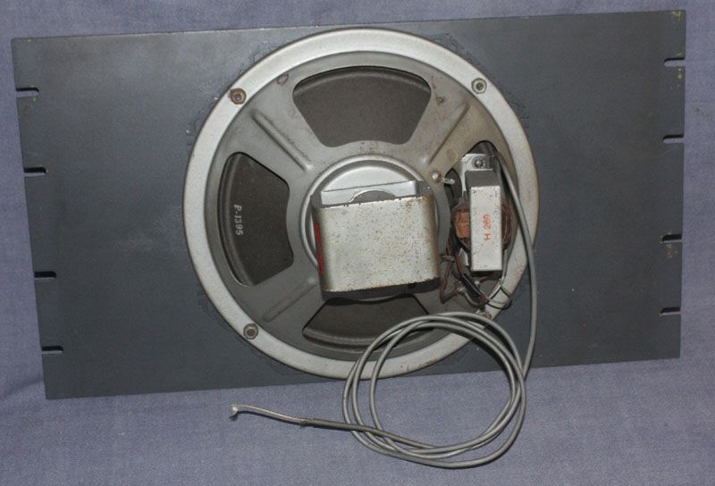
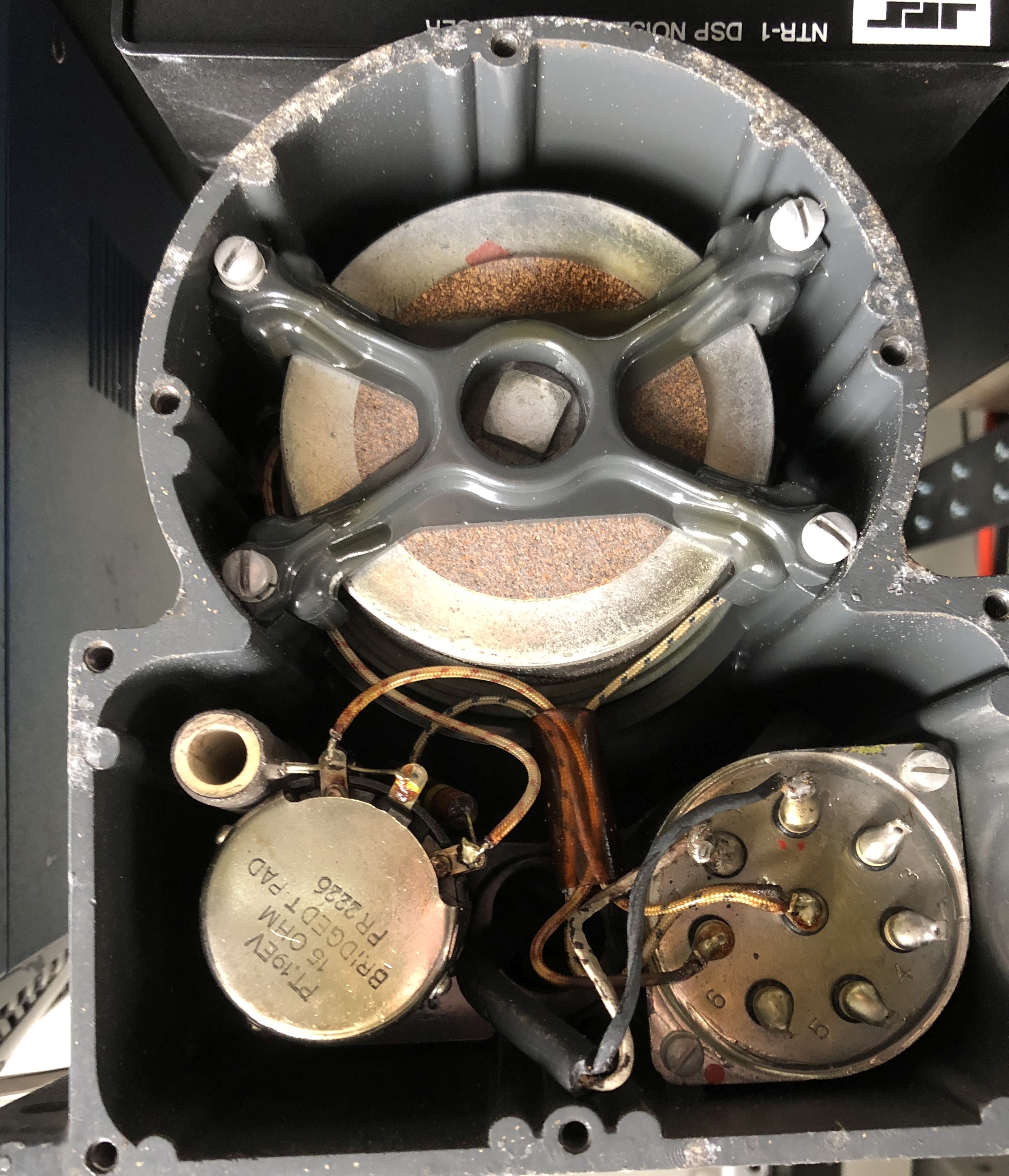
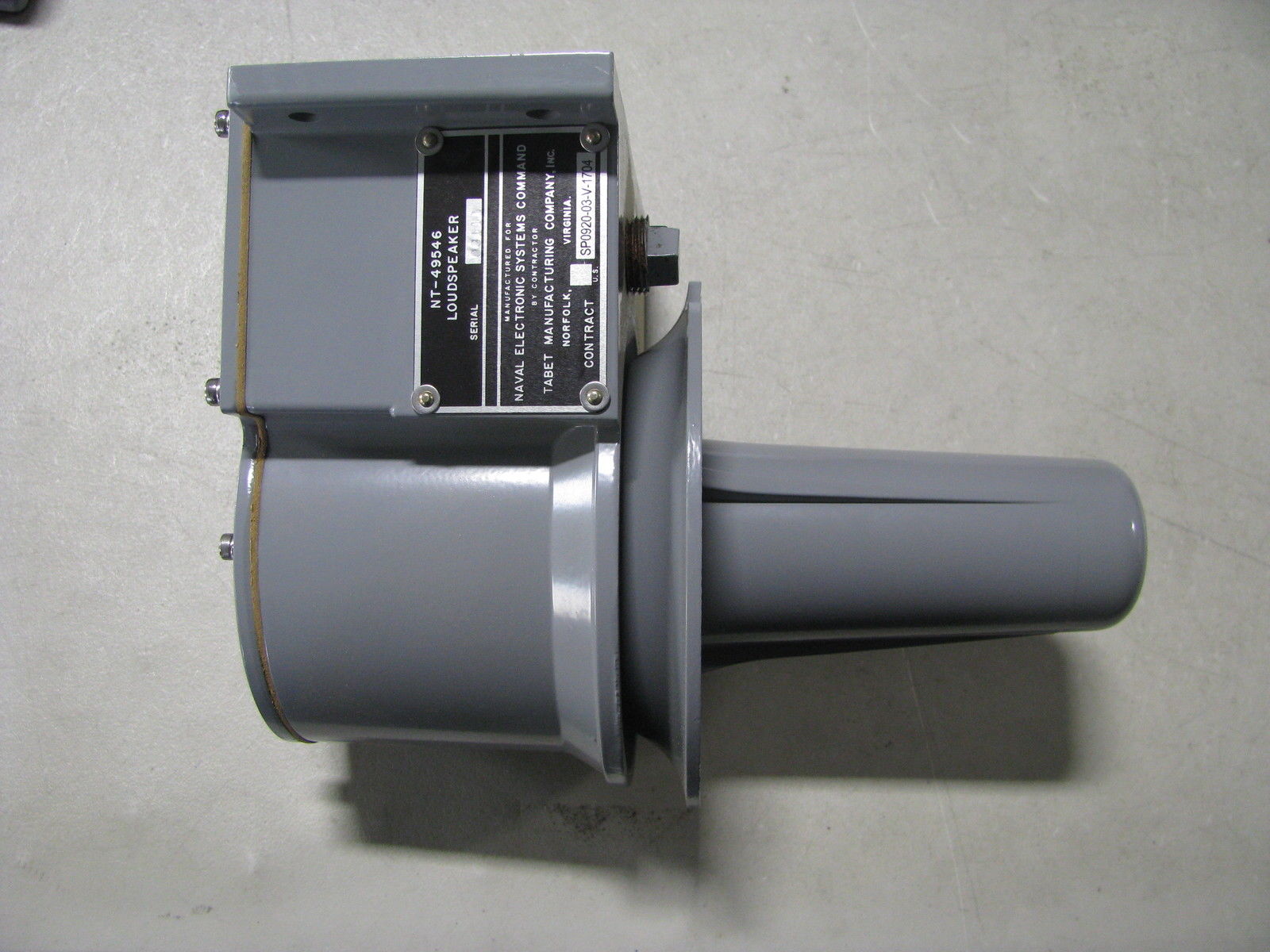
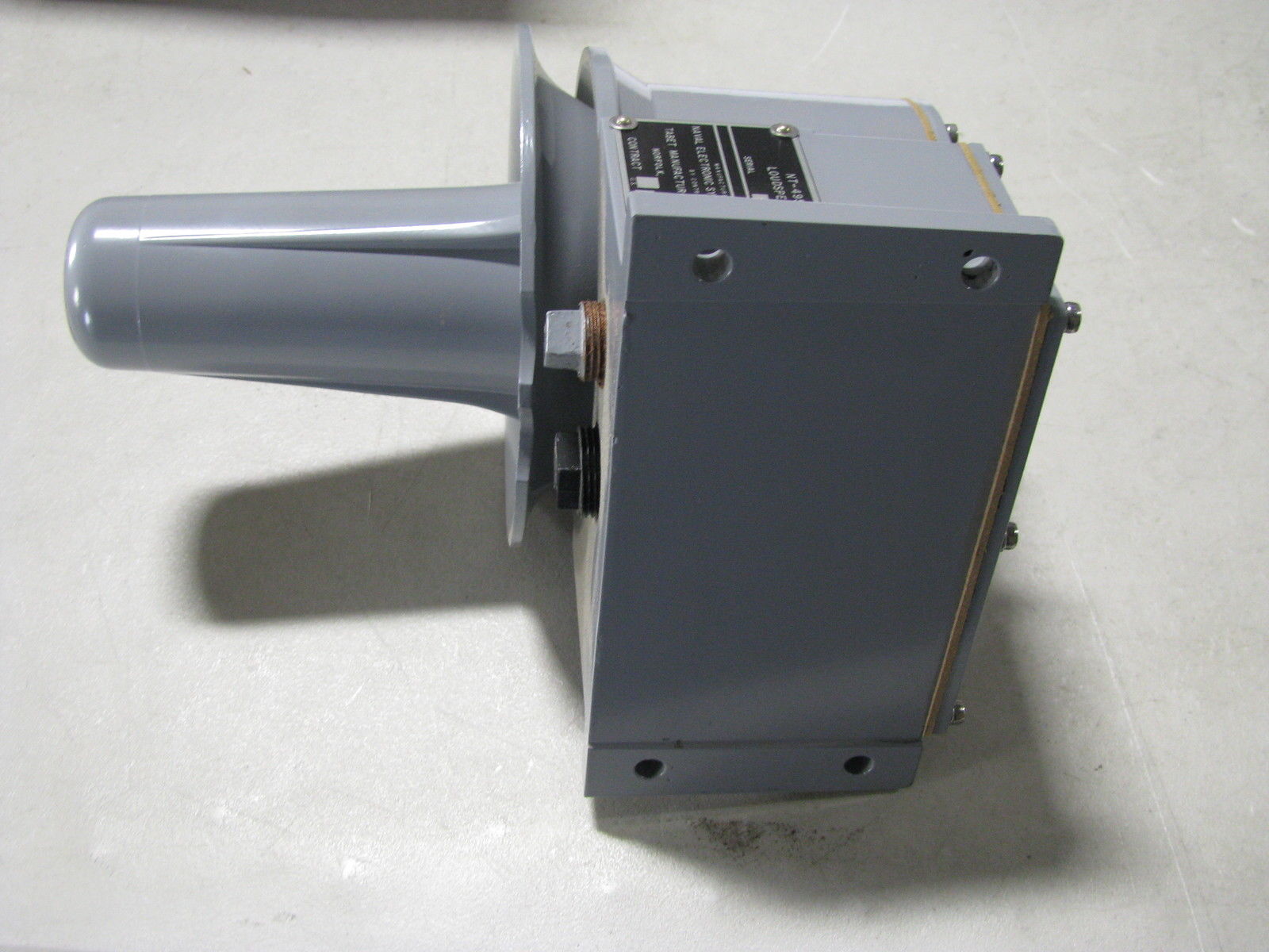
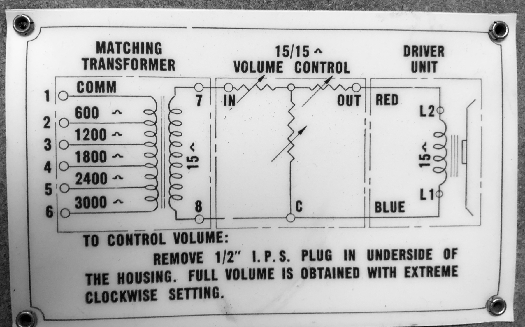
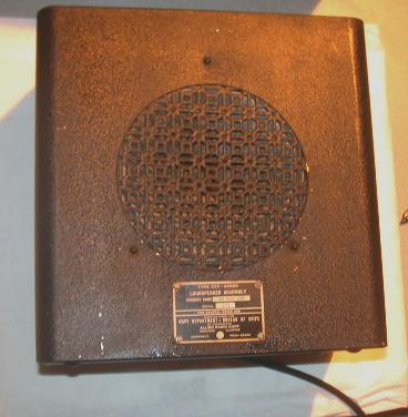
NT-49546 Loudspeaker
|
 |
general radio use manuf CUL University manuf Tabet 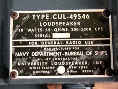 |
 |
 |
 |
 |
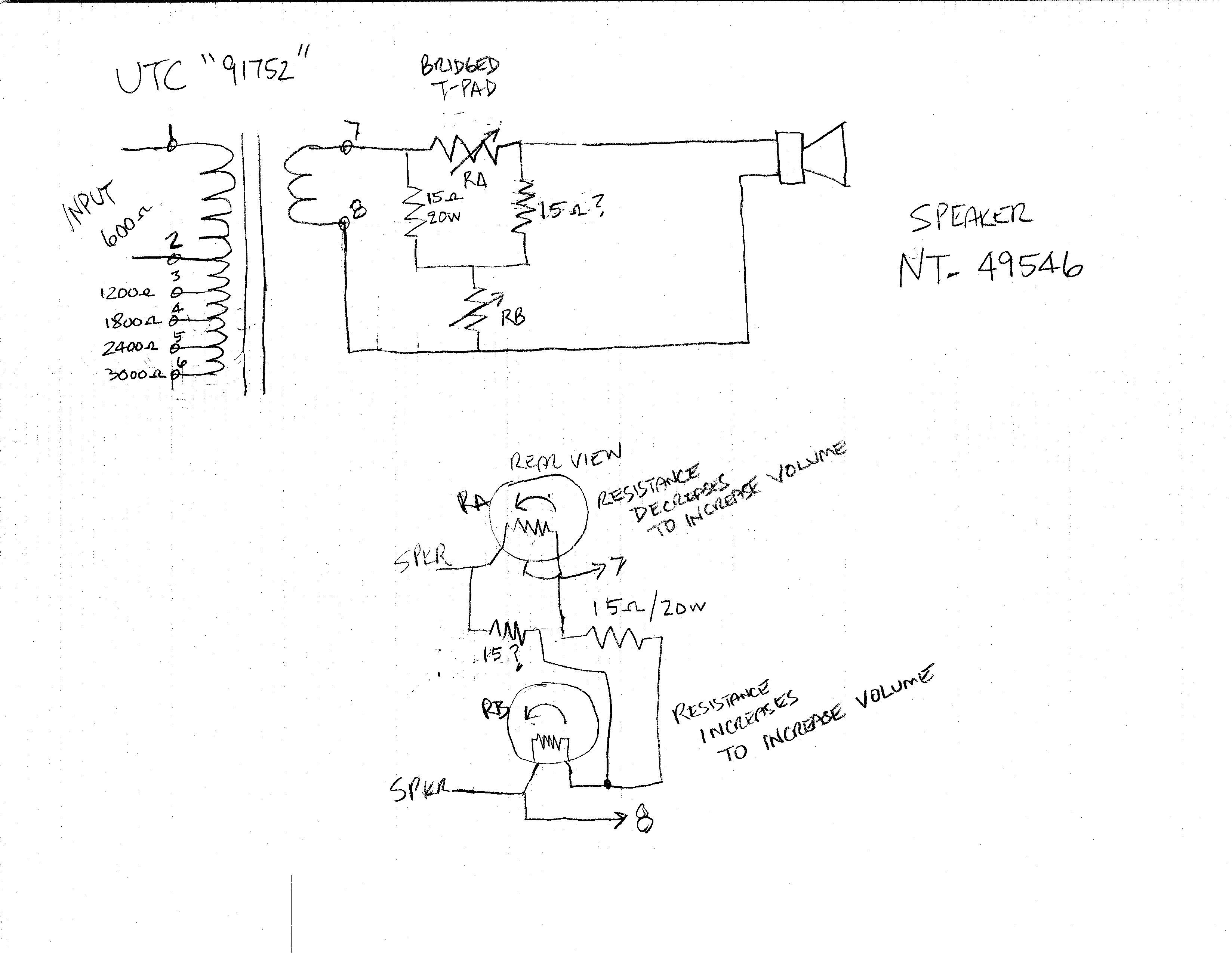 |
| Although it is a general-purpose communication loudspeaker, the NT-49546 is used principally for reproducing voice transmissions. The unit can be connected directly to a radio receiver, or it can be operated through an audio amplifier unit, such as the AM/215( )/U. Best results are obtained with the audio amplifier unit. The loudspeaker, designed as a watertight and shockproof unit for installation in exposed areas, also is used extensively in such spaces as the pilothouse and CIC. It usually is mounted on the bulkhead above or near its controlling amplifier unit. | |||
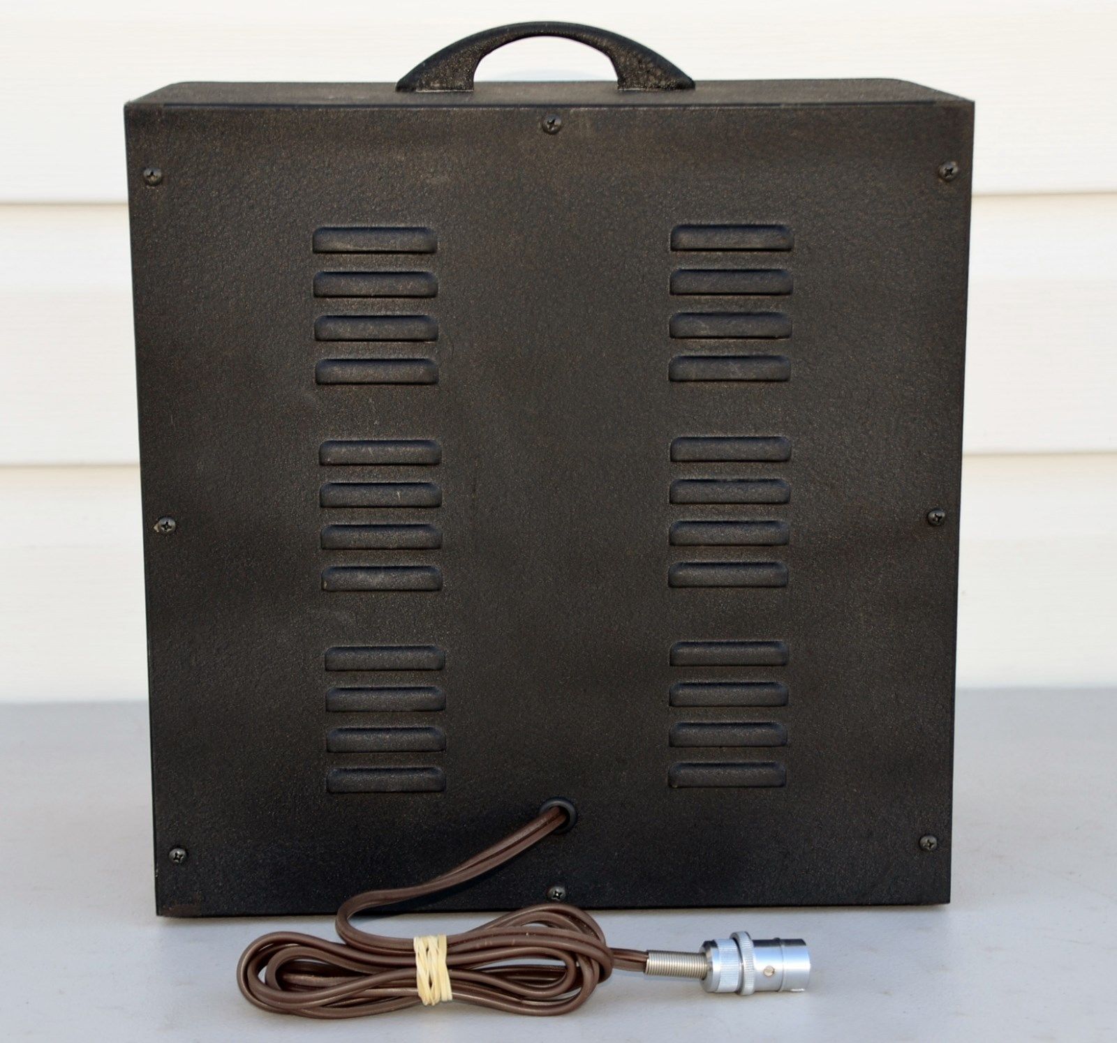
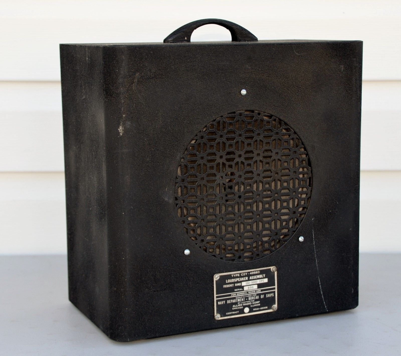
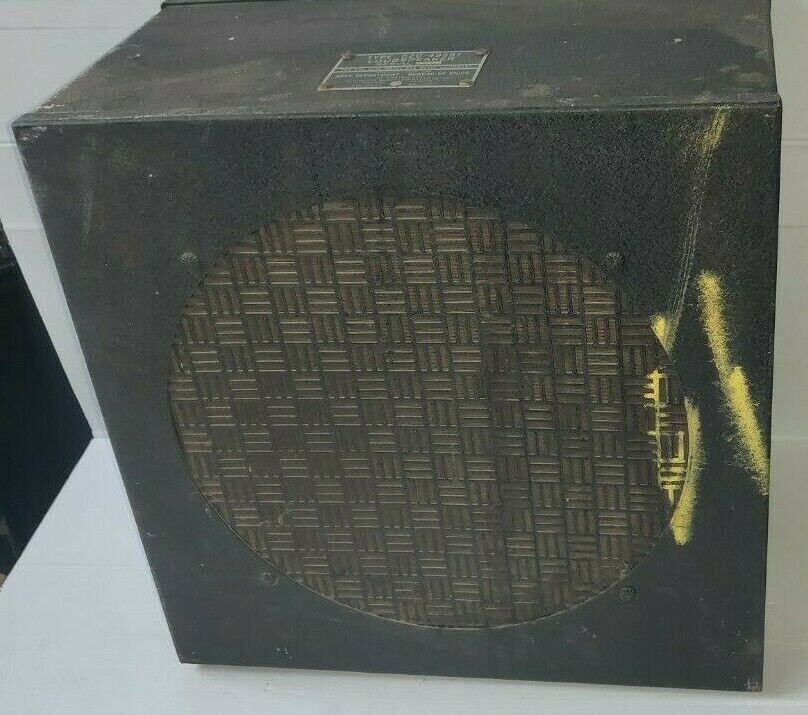
CZY-49583
|
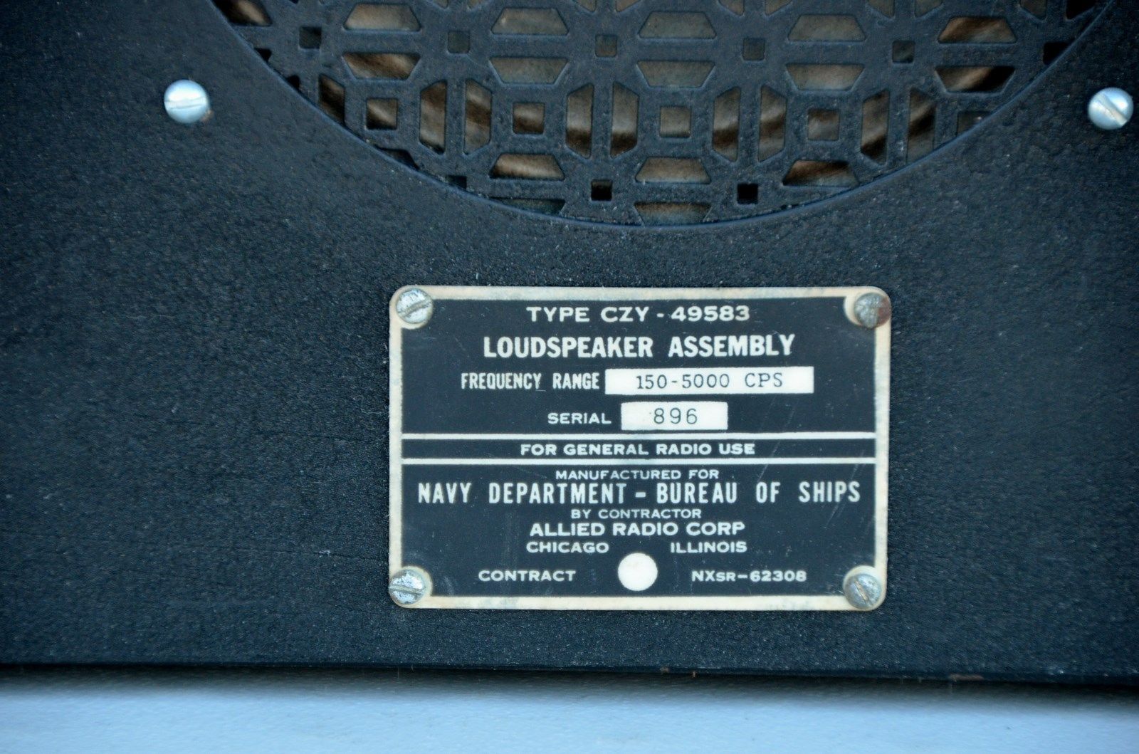
manuf CZY Allied Radio |
 |
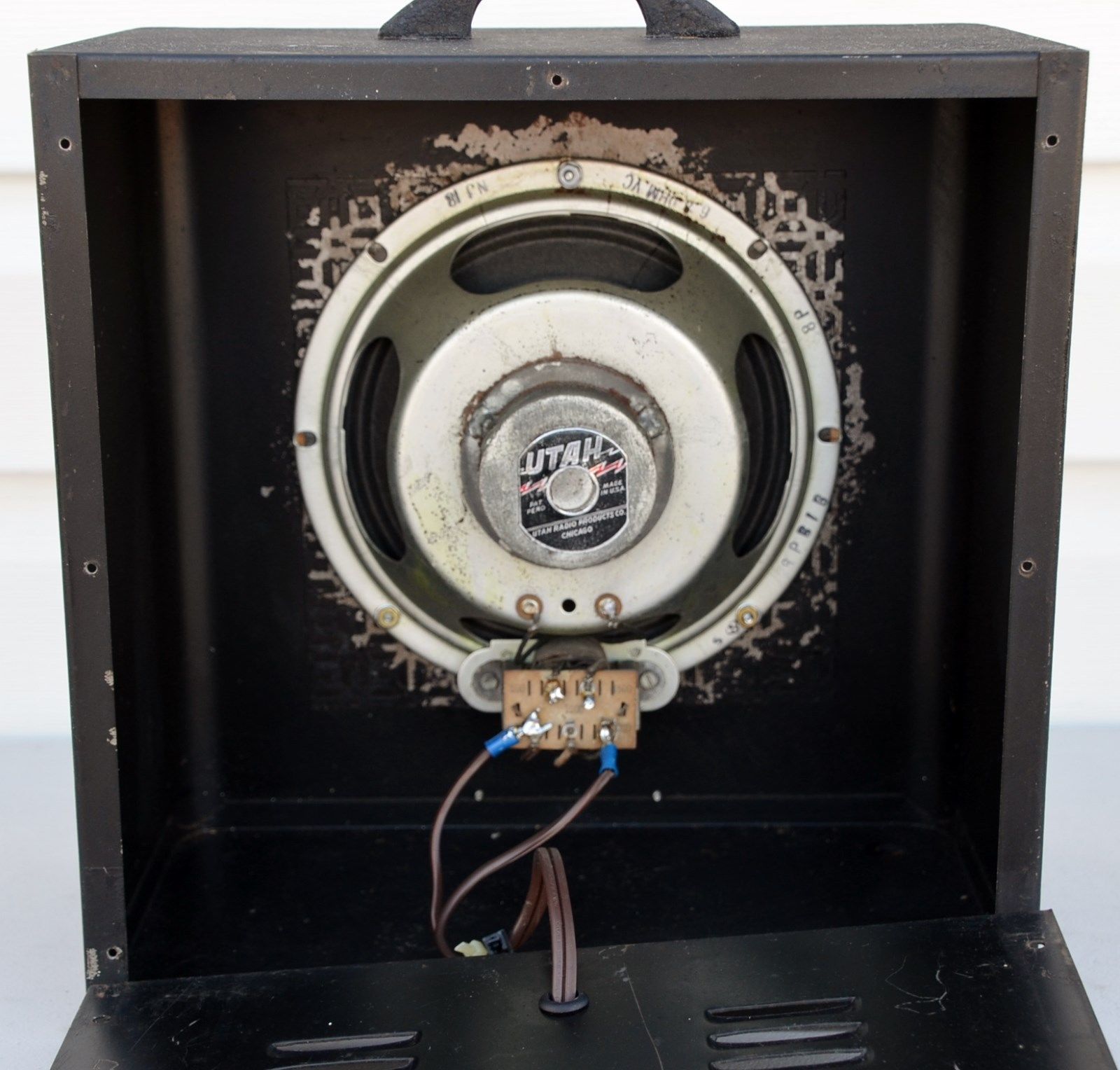 |
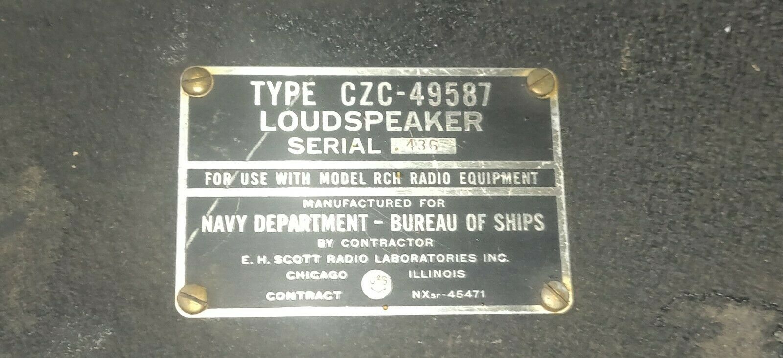
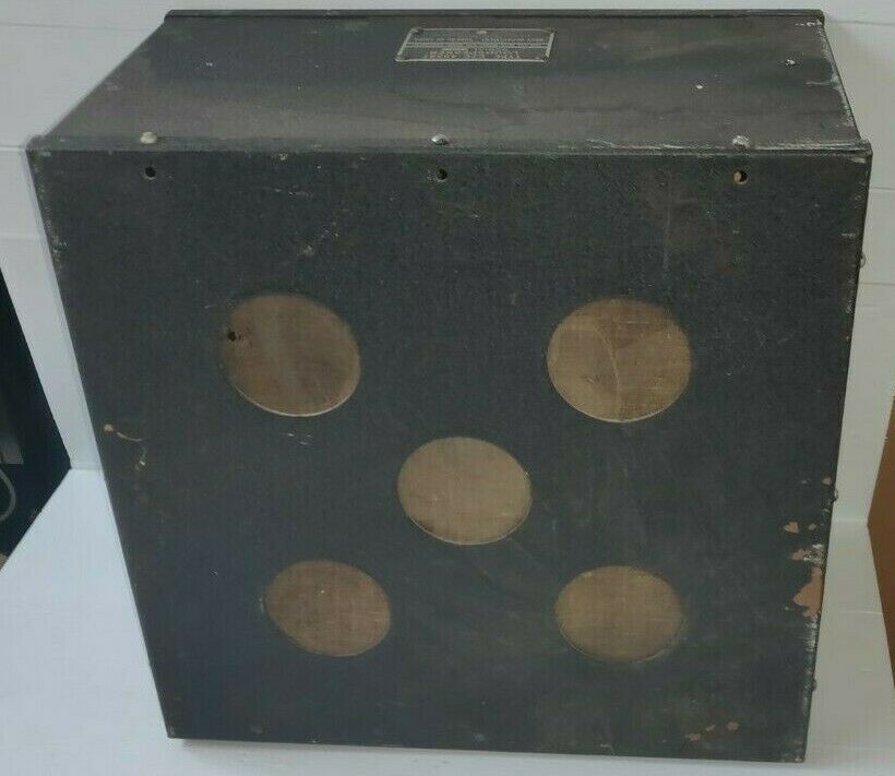
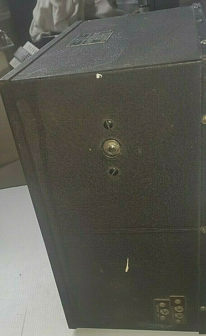
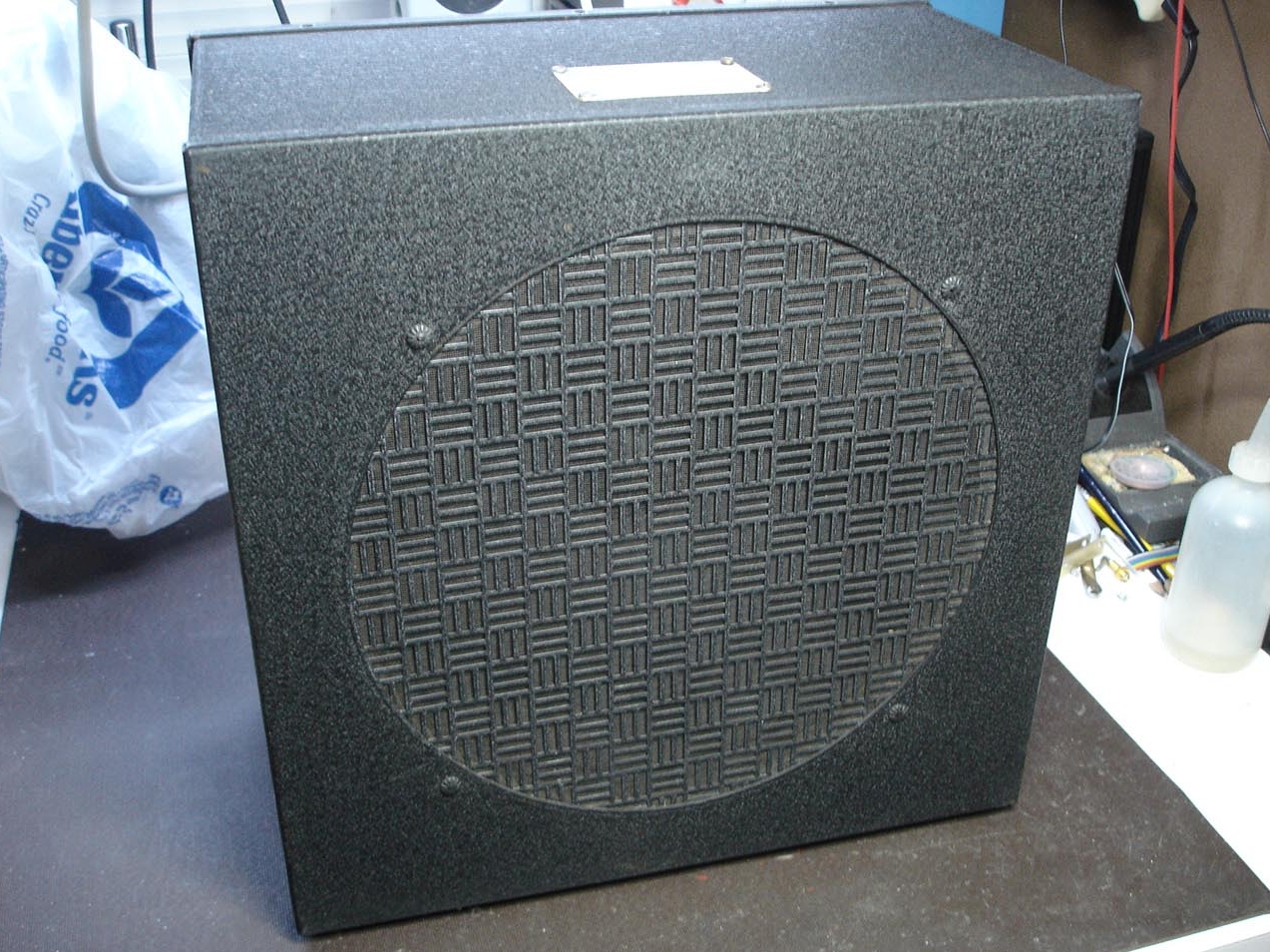
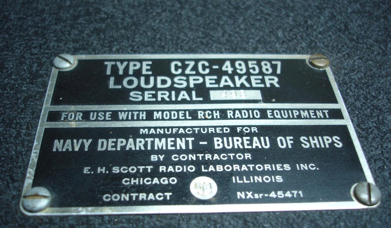
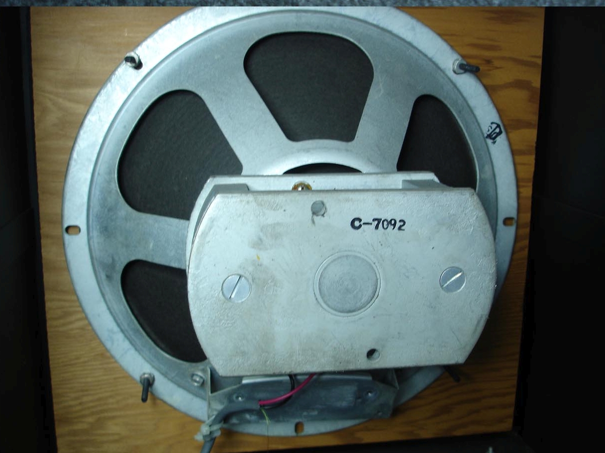
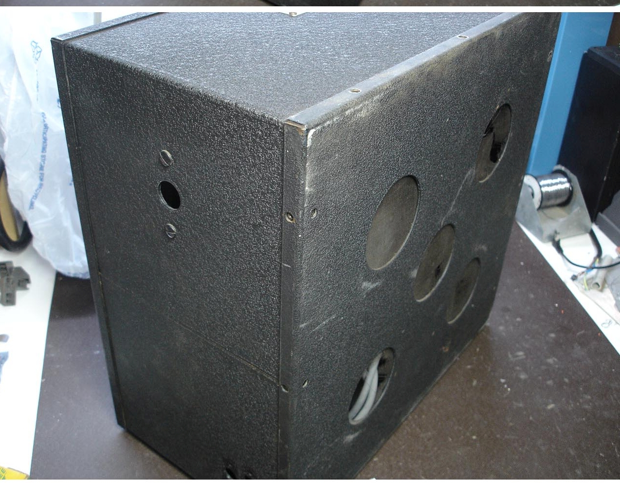
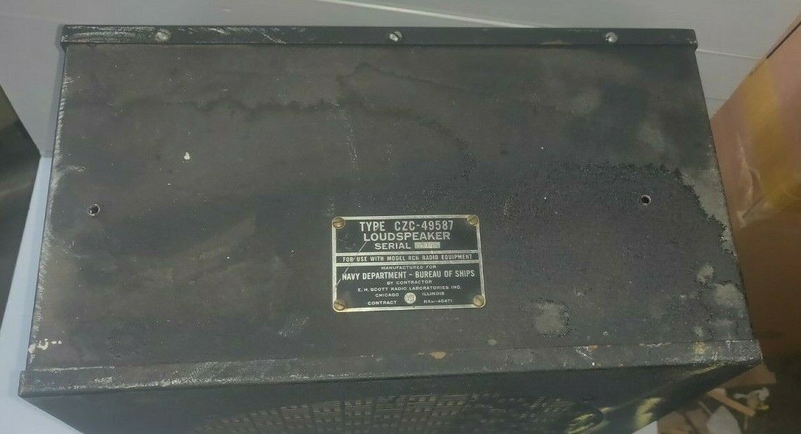
CZC-49587 (used with RCH)
|
|
 |
 |
 |
 |
 |
 |
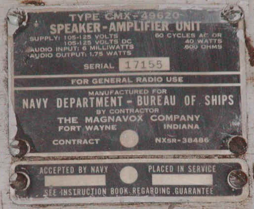
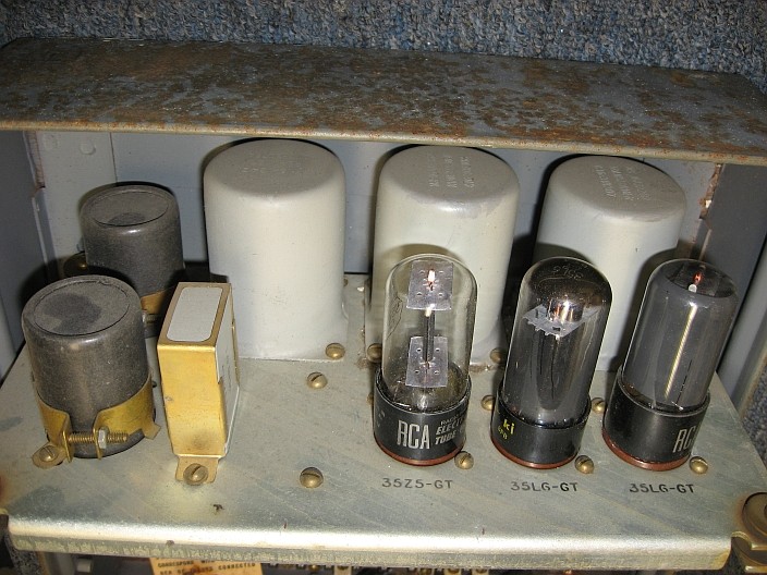
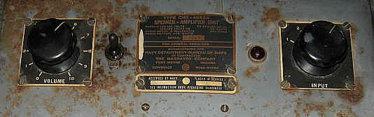
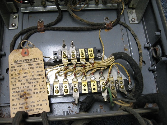
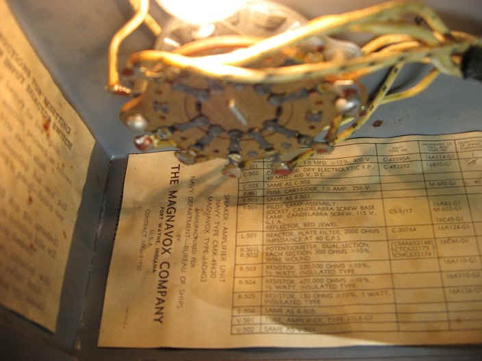
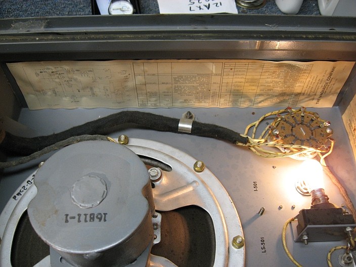
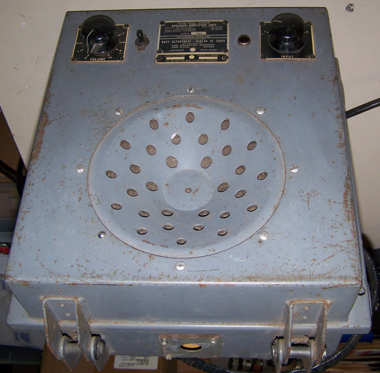
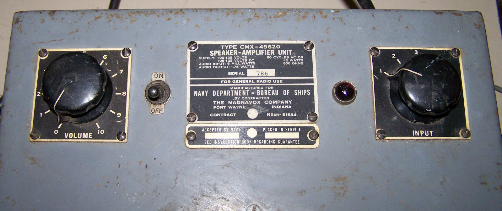
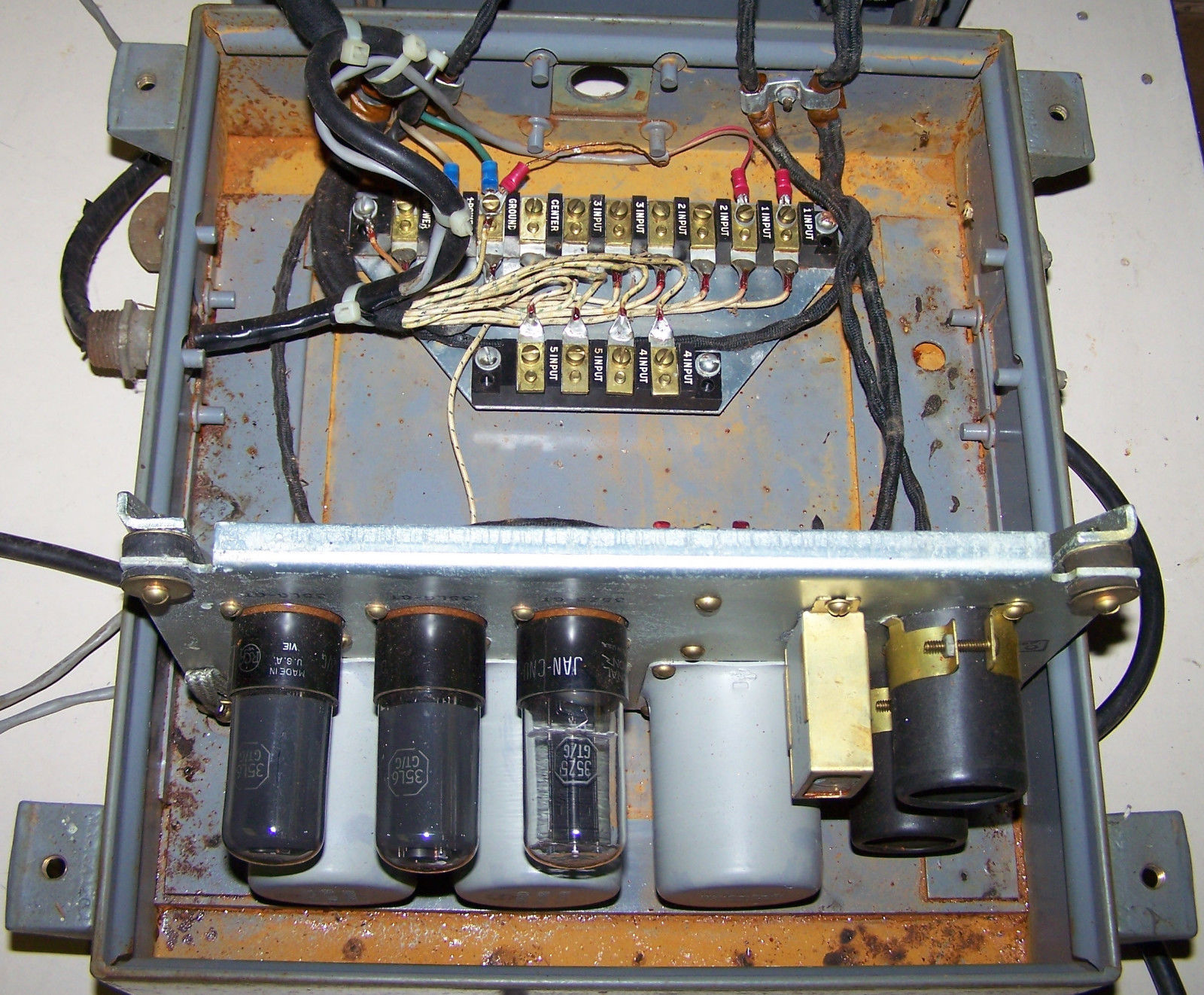
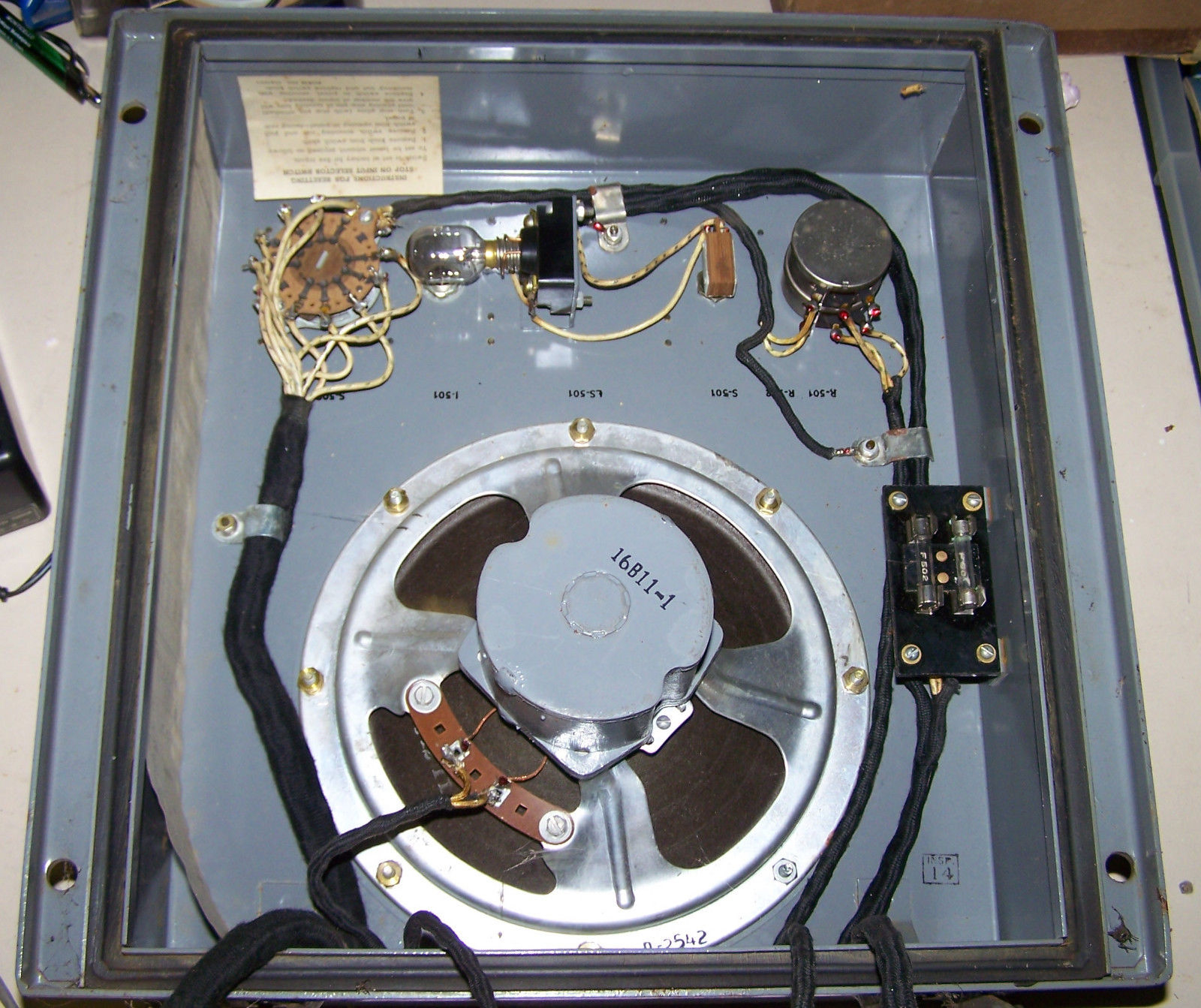
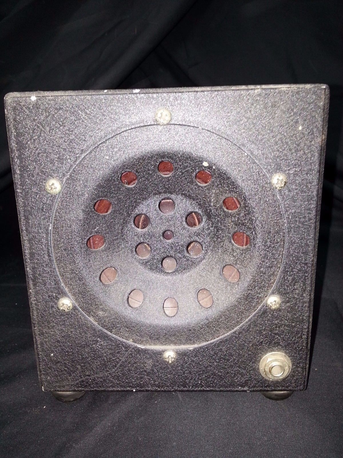
CMX-49620 amp/speaker
|
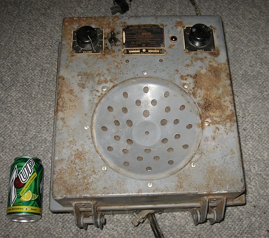 |
Amp & 8" Speaker
|
 |
 |
 |
|
manuf CMX Magnavox-
|
 |
 |
 |
-- |
 |
|
 |
|
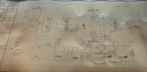
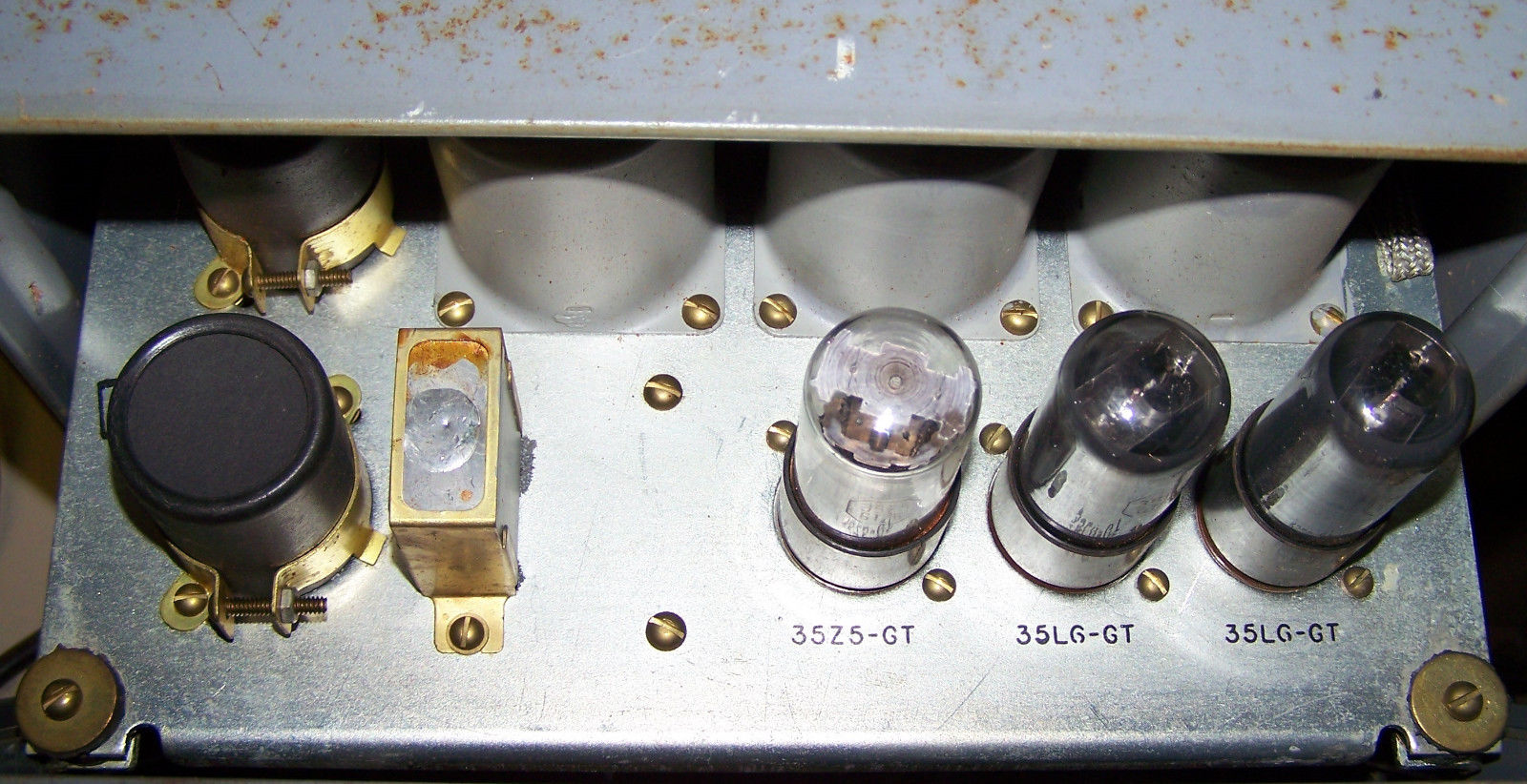
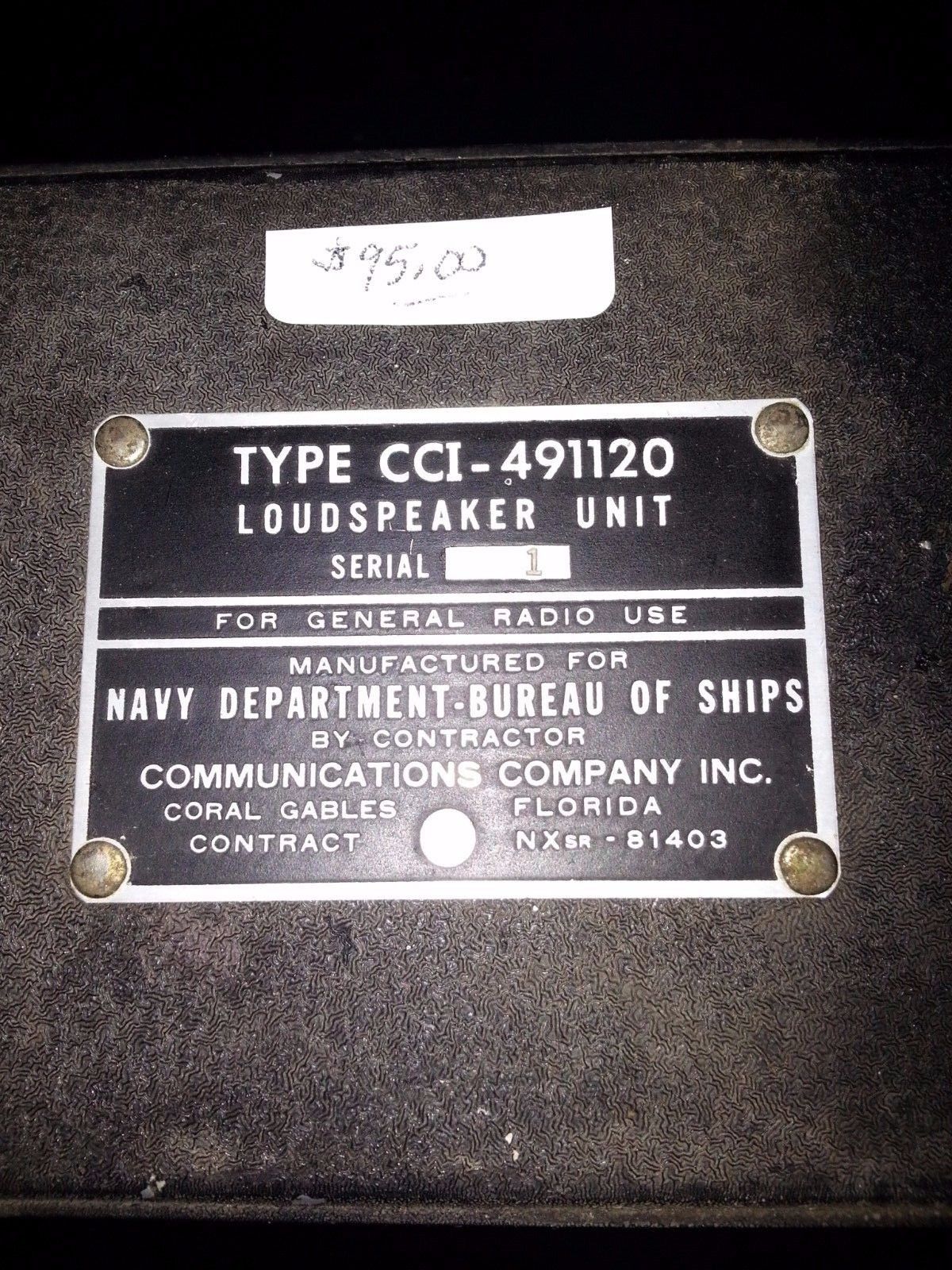
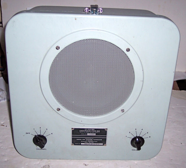
CCI-491120
|
 |
 |
== |
General Purpose & PA loudspeakers (Interior Communications) |
|||
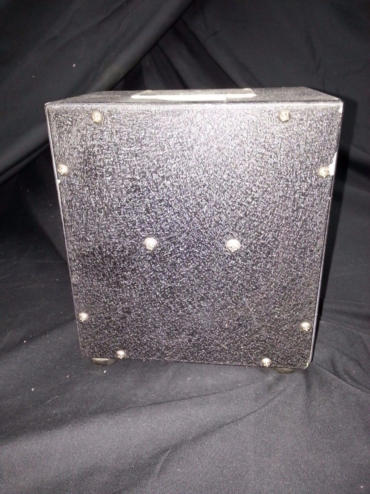
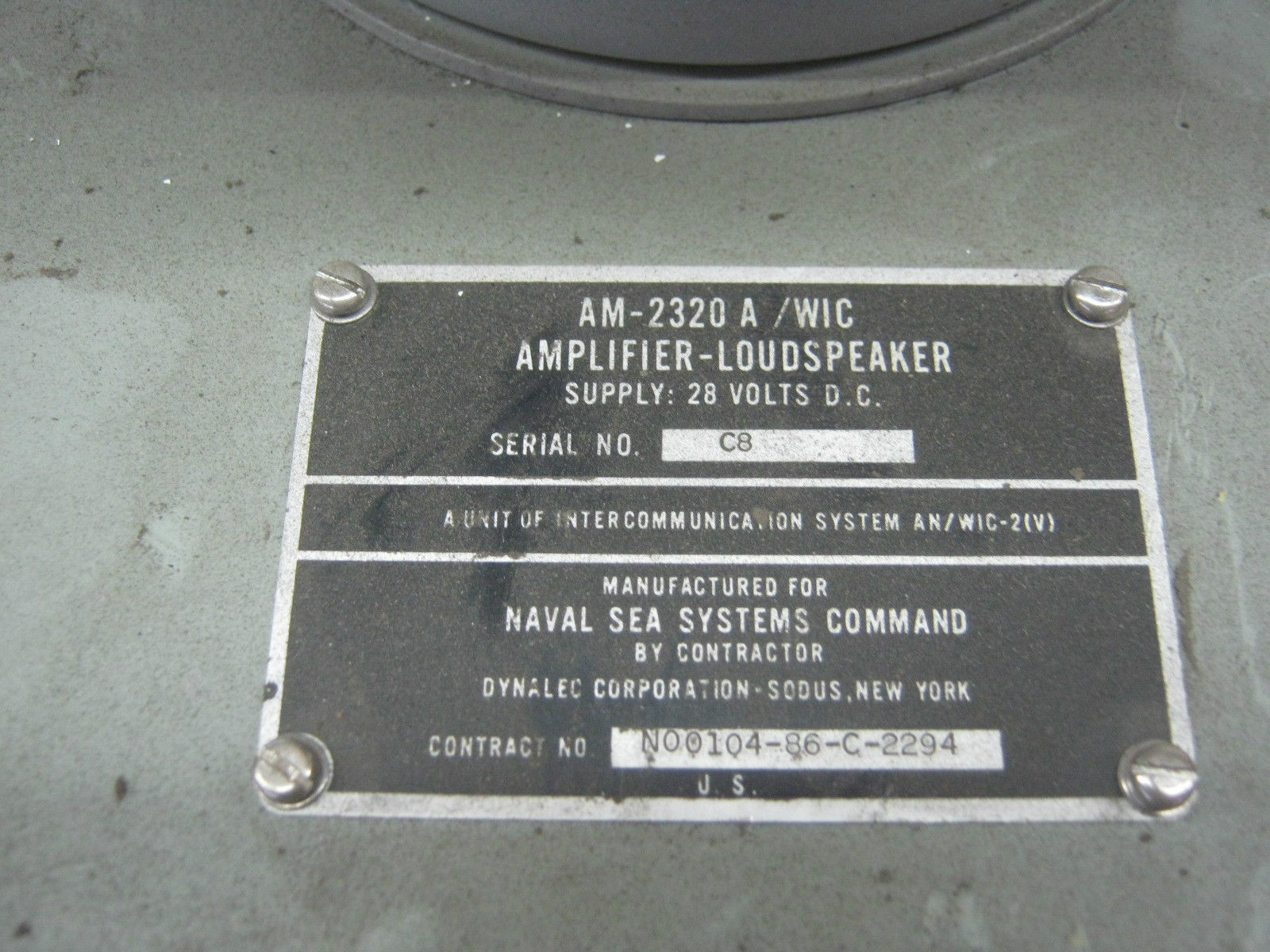
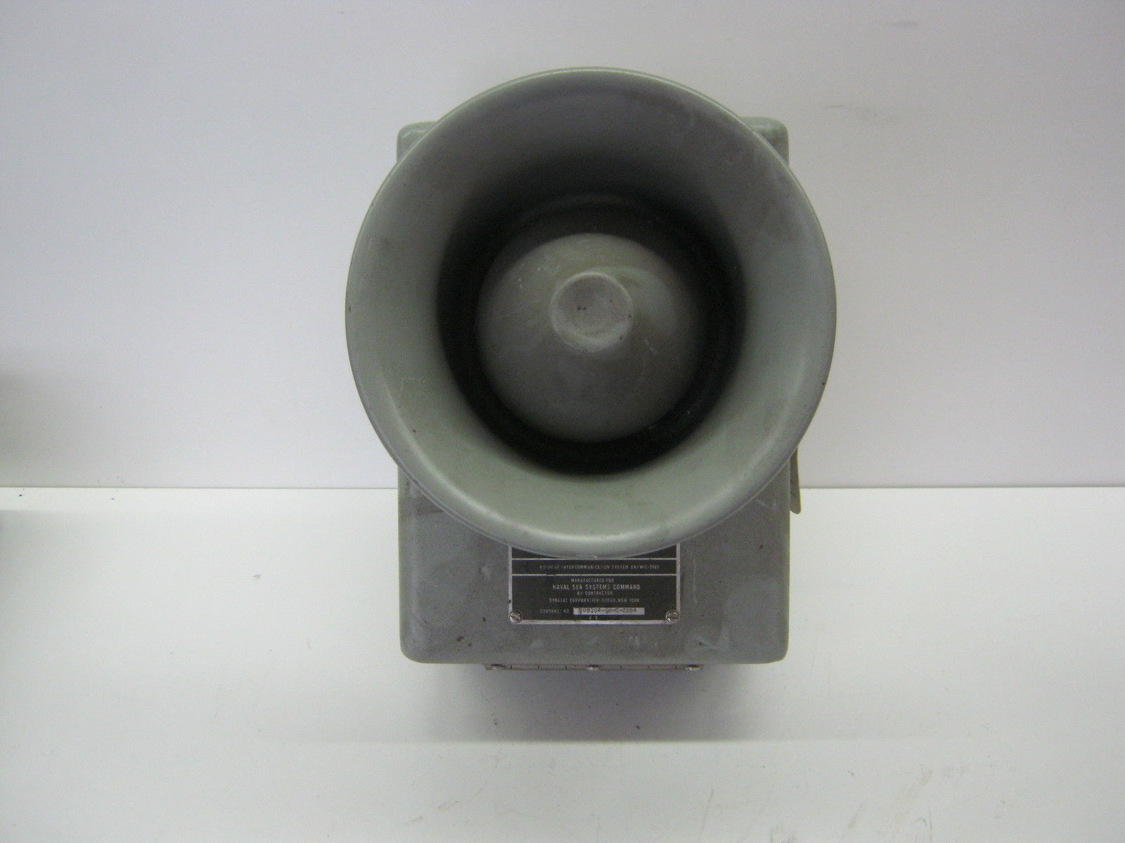
AM-2320A/WIC amplifier-loudspeaker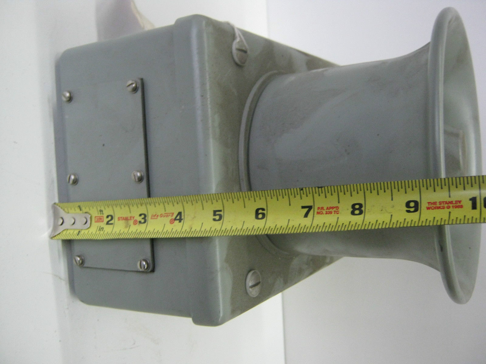 |
 |
 |
|
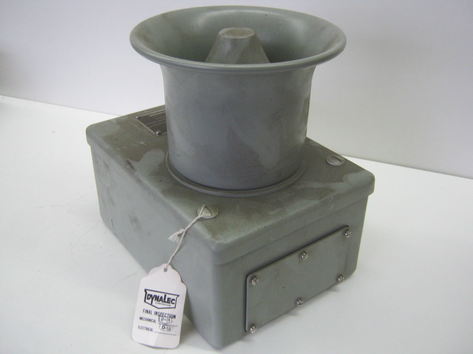
LS-305/SIC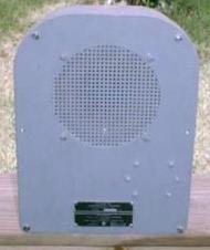 |
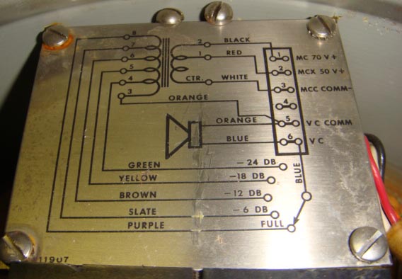
 70v line input. Transformer taps give up to -24dB attenuation |
 |
manuf Tabet, Dynalec
Download spec sheet |
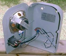
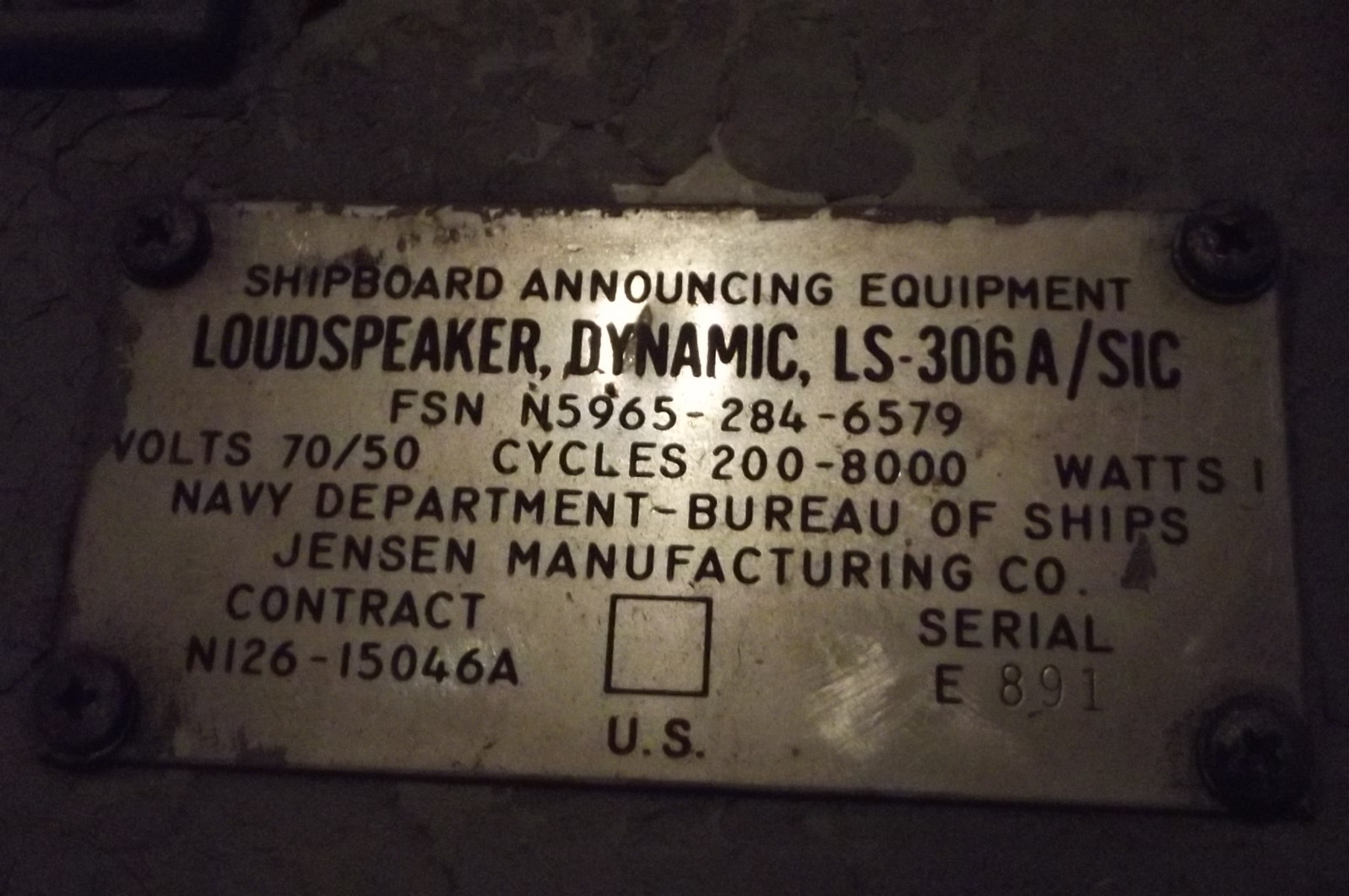
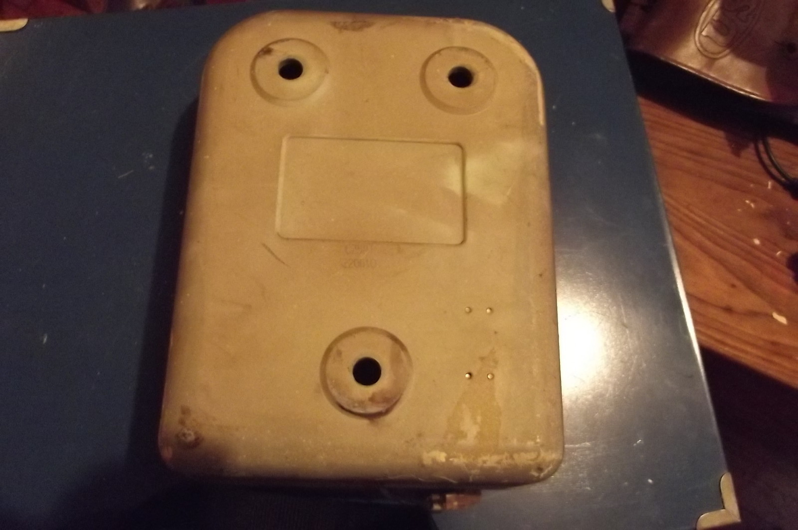
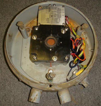
LS-306A/SIC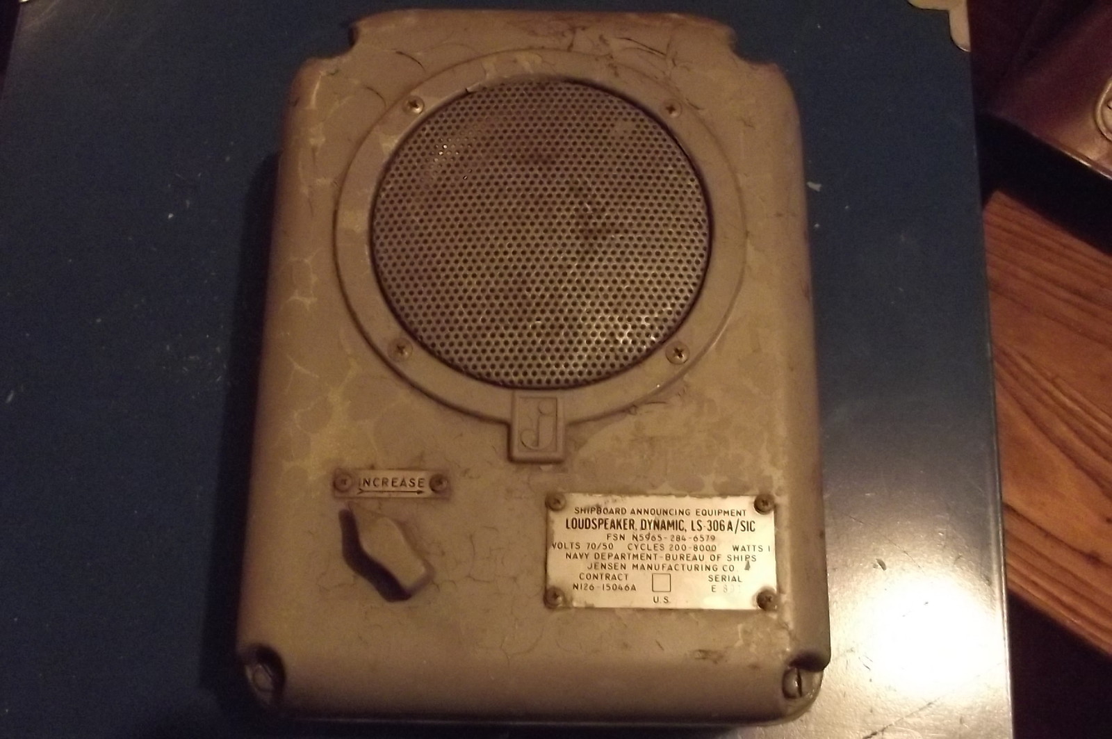 |
 |
 |
== |
LS-388/SIC |
 70v line |
 |
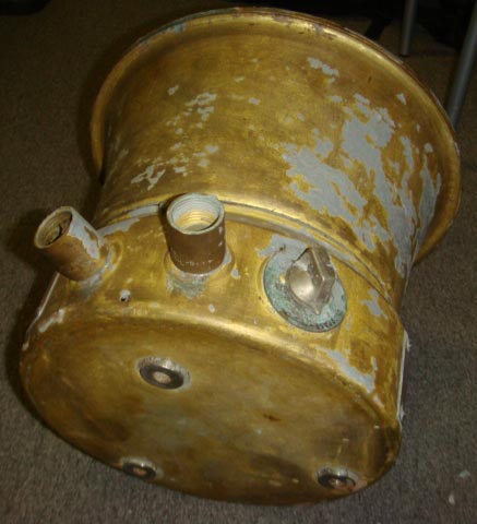 |
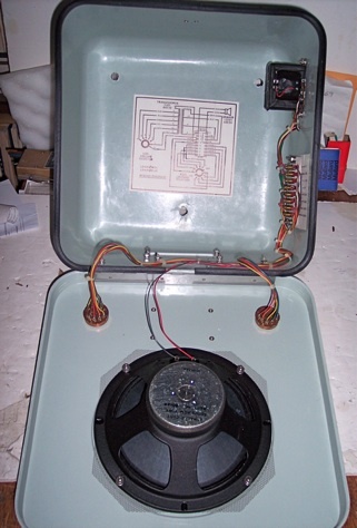
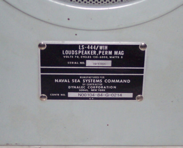
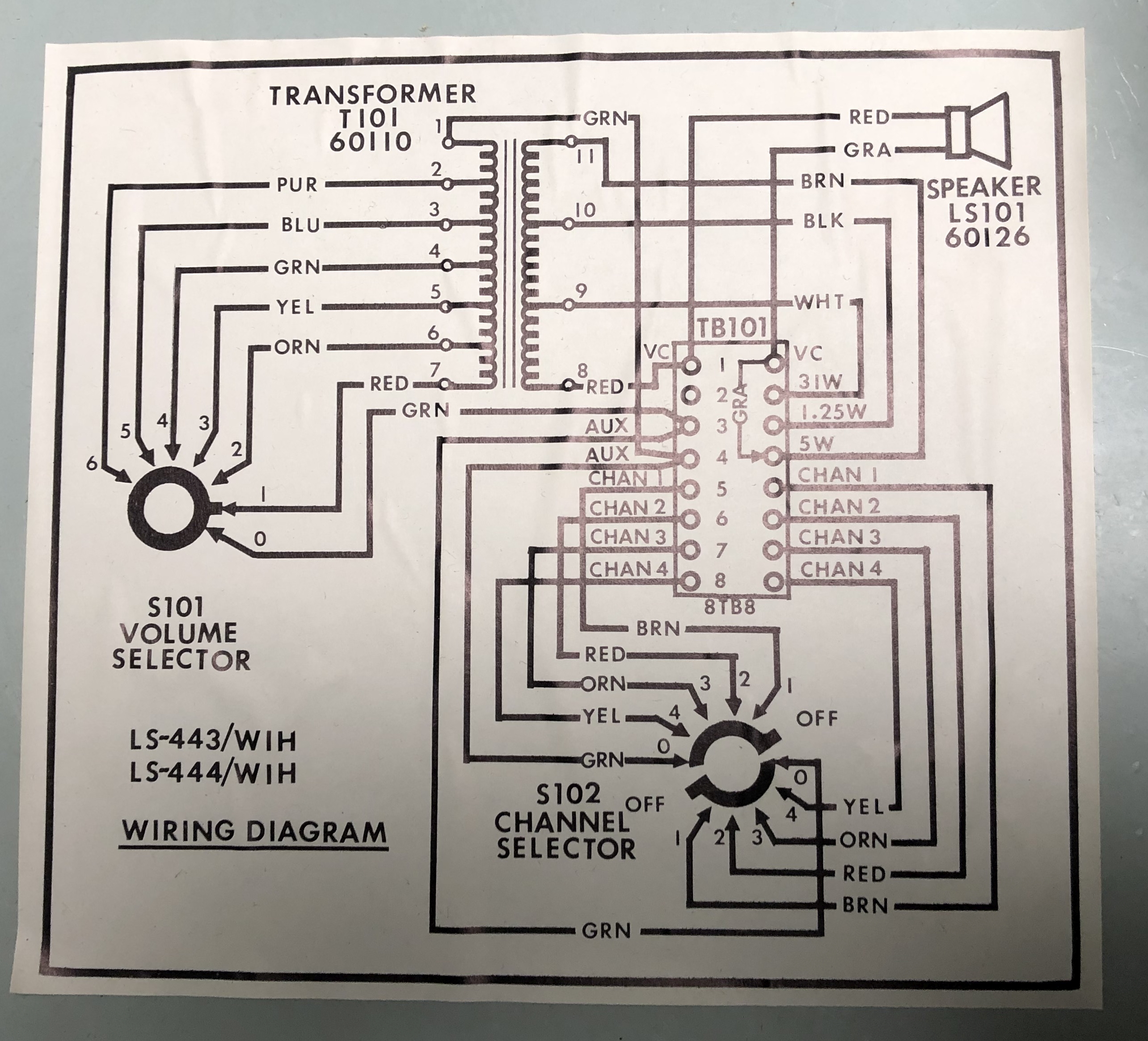
LS-444/WIH, LS-443/WIH
Manual - thanks to K7HUE
|
 |
|
 |
LS-519/SIC |
 |
||
LS-530/SIC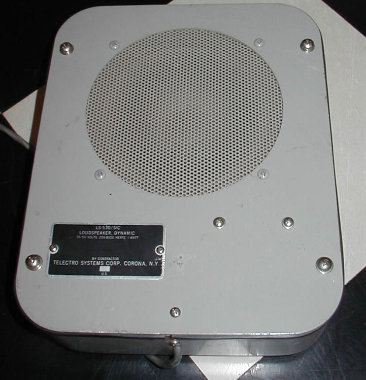 |
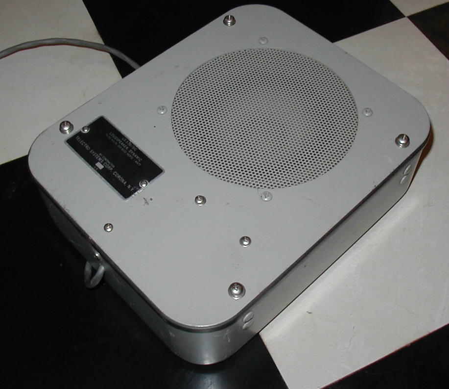 70v line input |
 |
manuf Telectro Systems |
LS-543/SIC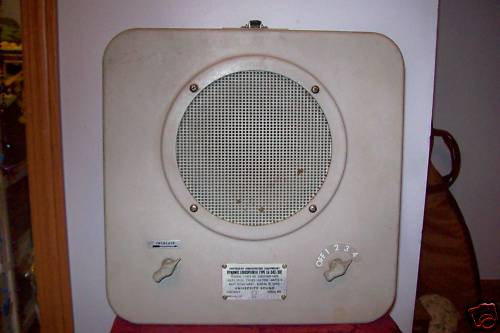 |
 |
- | manuf University |
RCA MI-2915-FA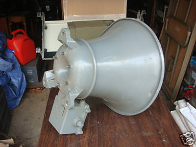 |
 |
 |
manuf RCA |
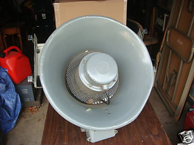
RCA MI-2917-J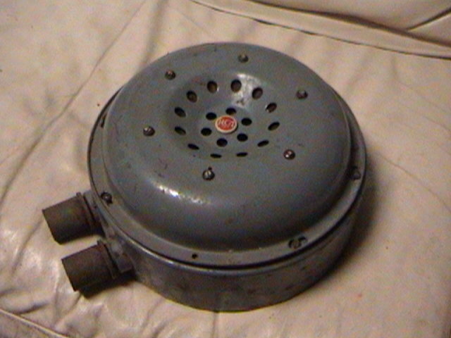 |
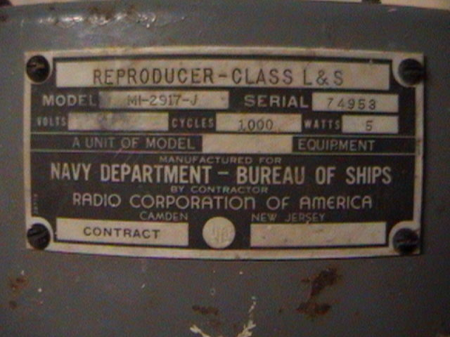 |
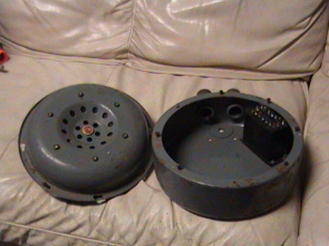 |
manuf RCA |
RCA 2917-S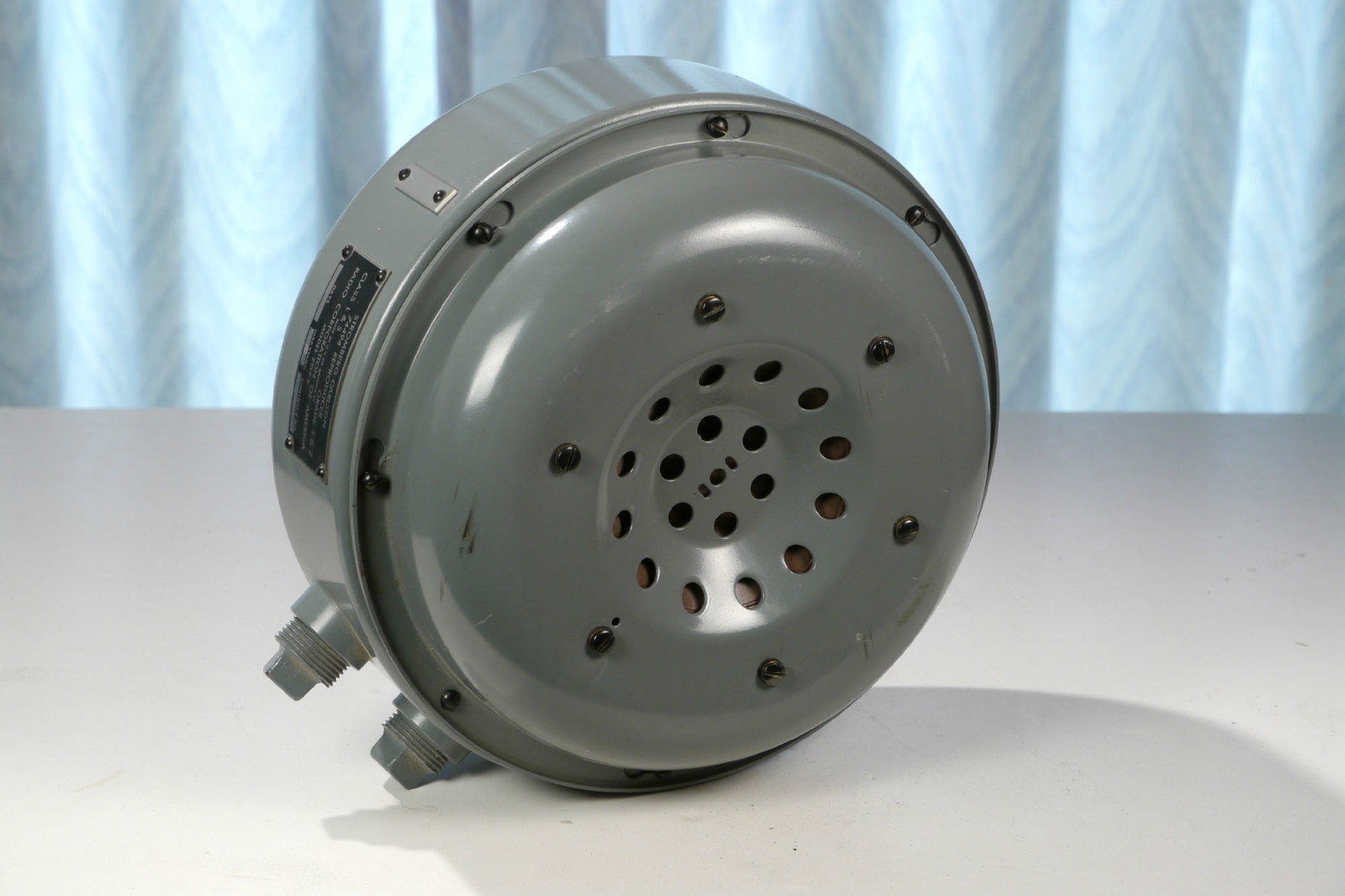 |
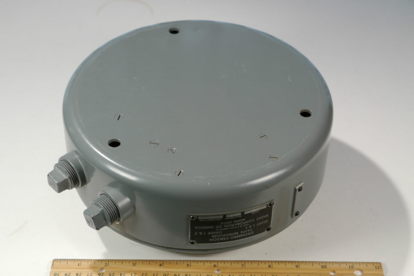 |
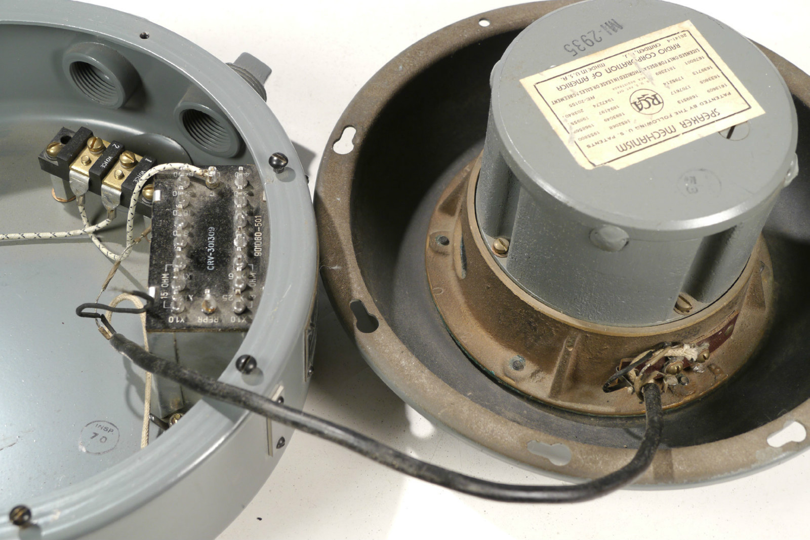 |
manuf RCA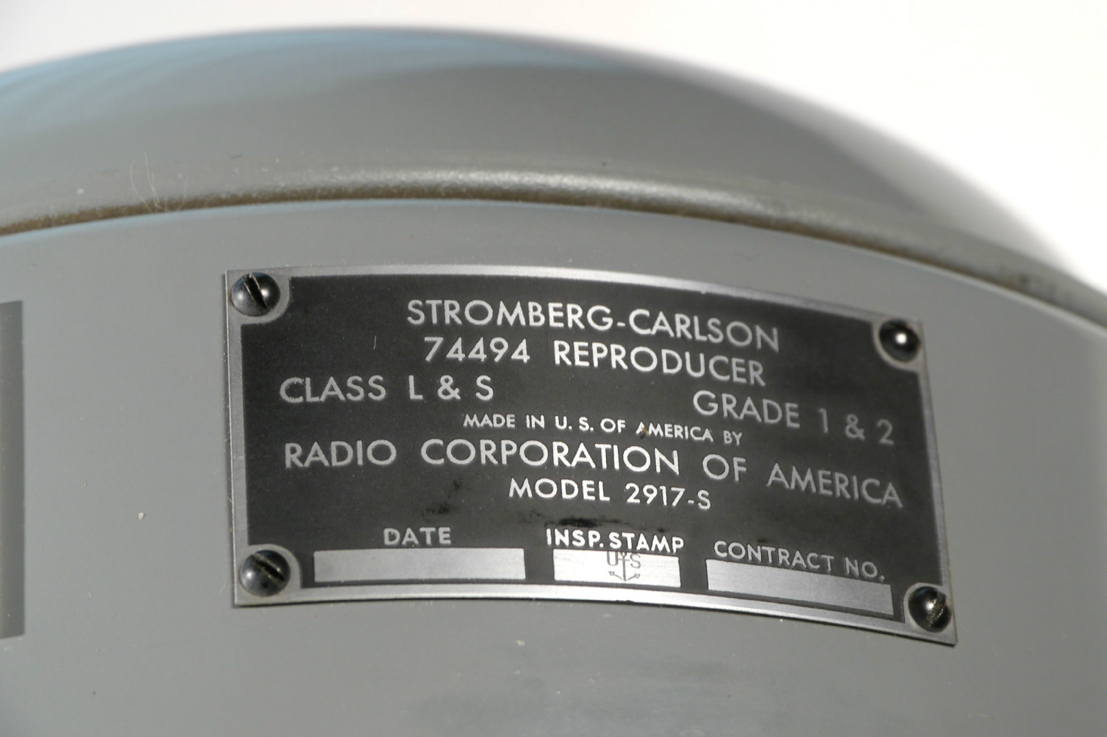 |
RCA MI-2961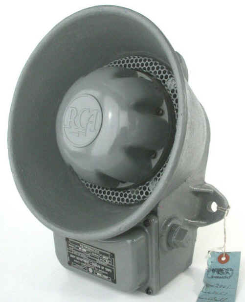 |
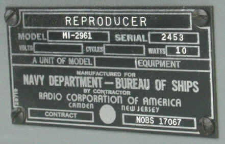 |
- | manuf RCA |
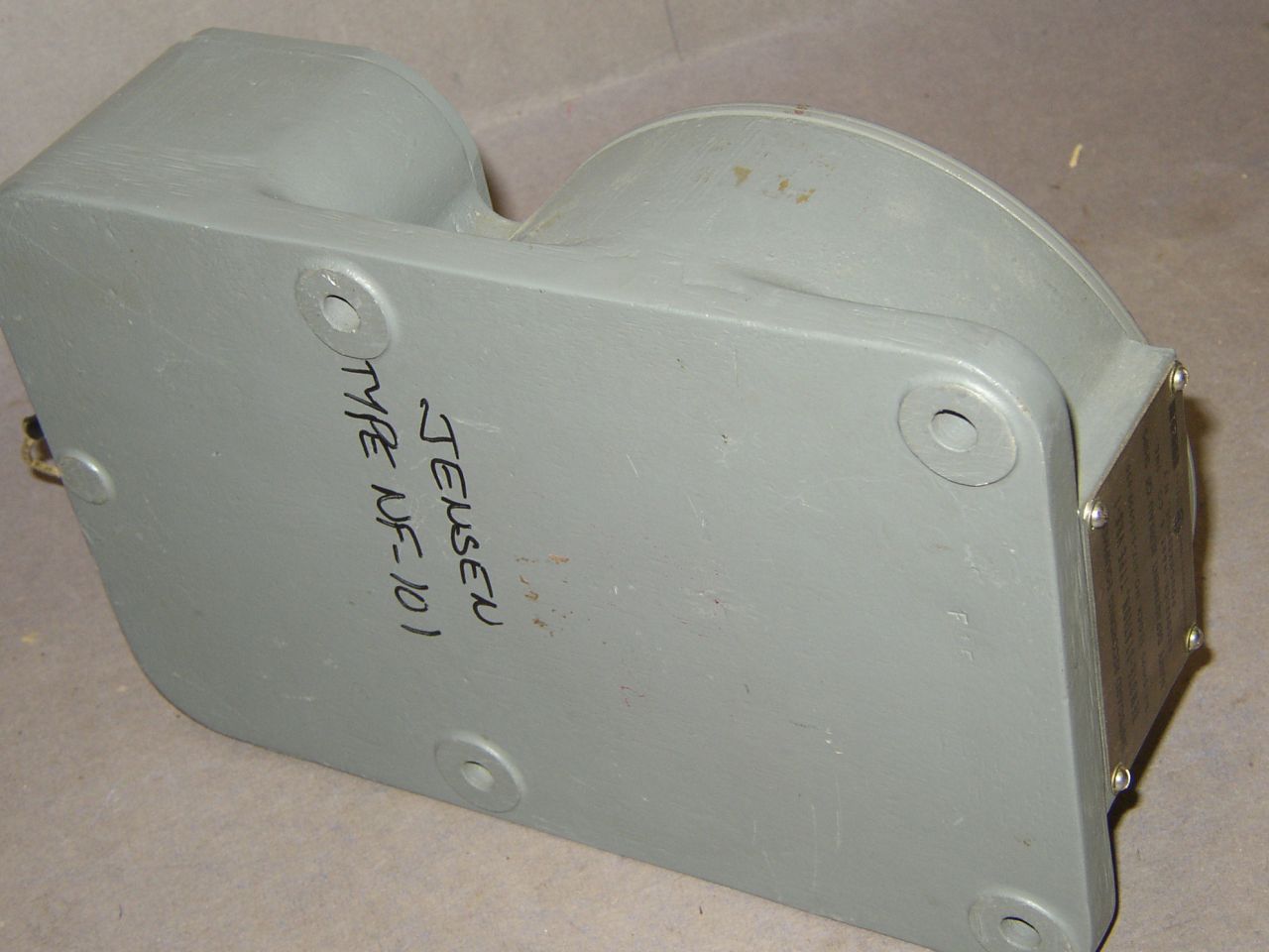
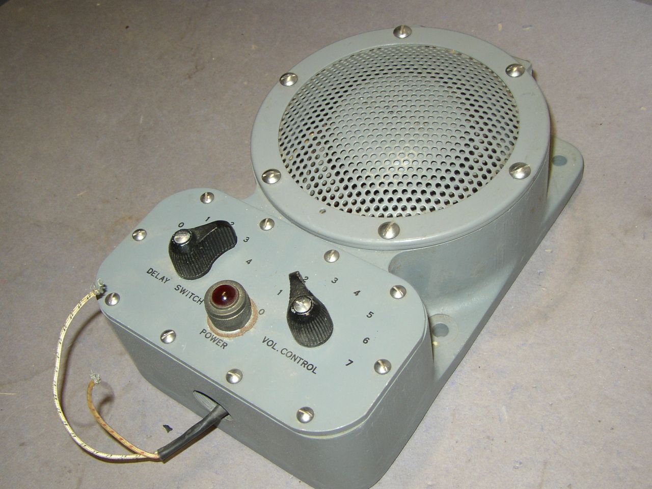
Jensen NA-10001 |
 |
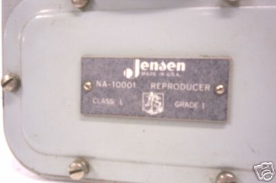 |
manuf Jensen |
VRS-1 recording equipment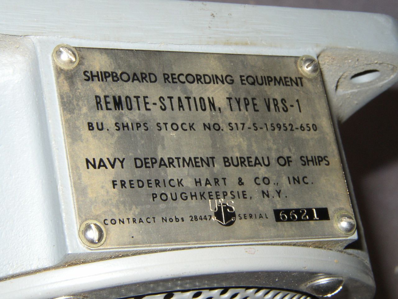 |
 |
 |
== |
Speakers for use with Underwater Sound Equipment |
|||
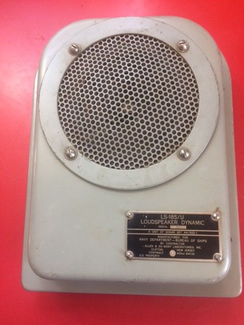
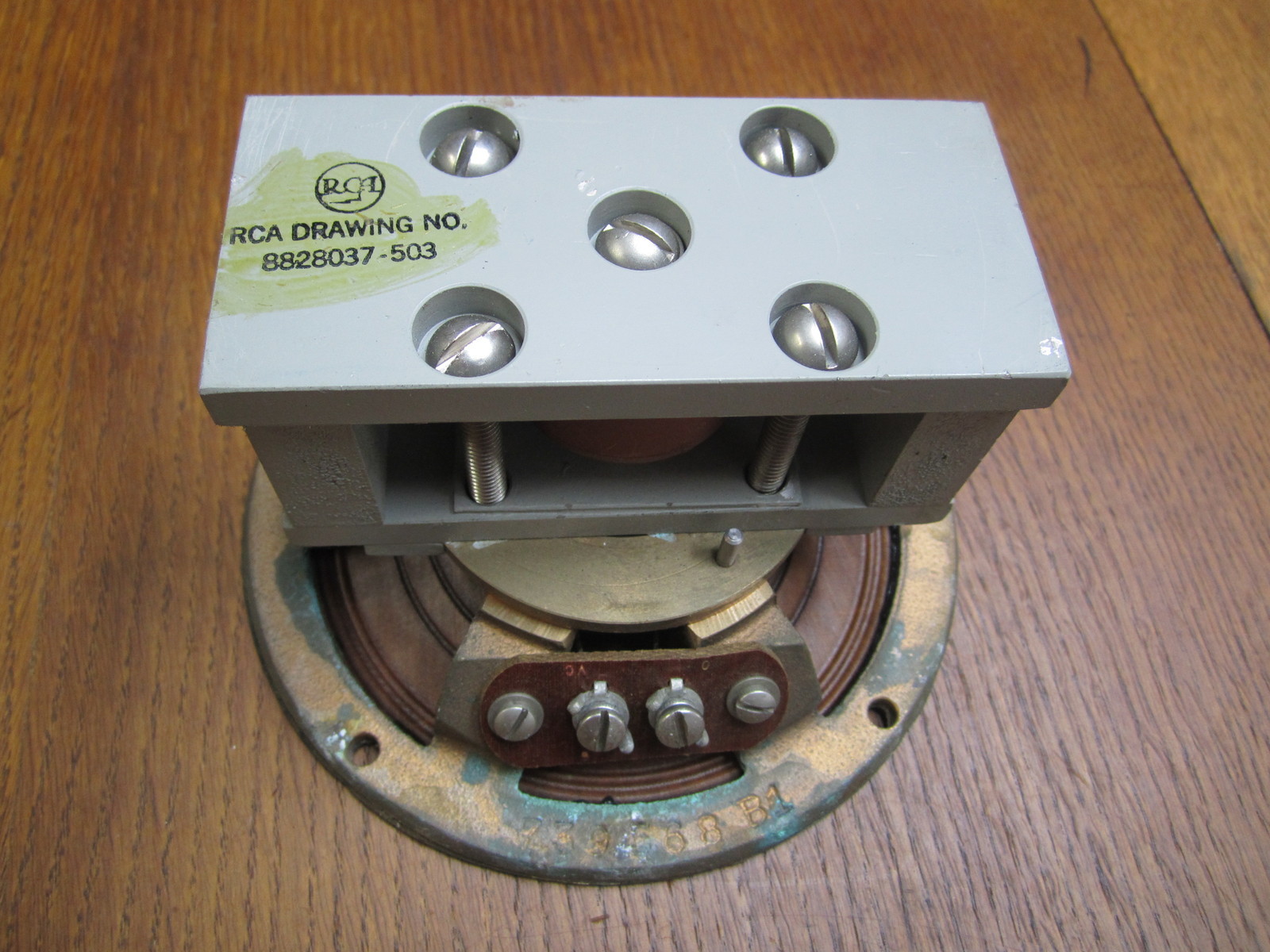
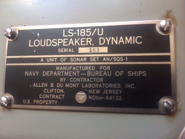
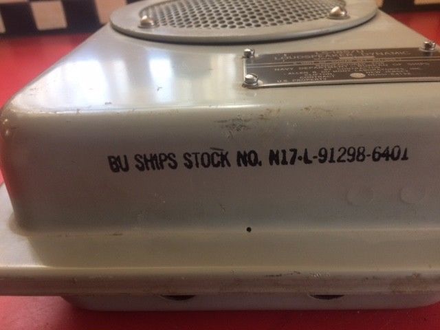
LS-185/U for AN/SQS-1 Sonar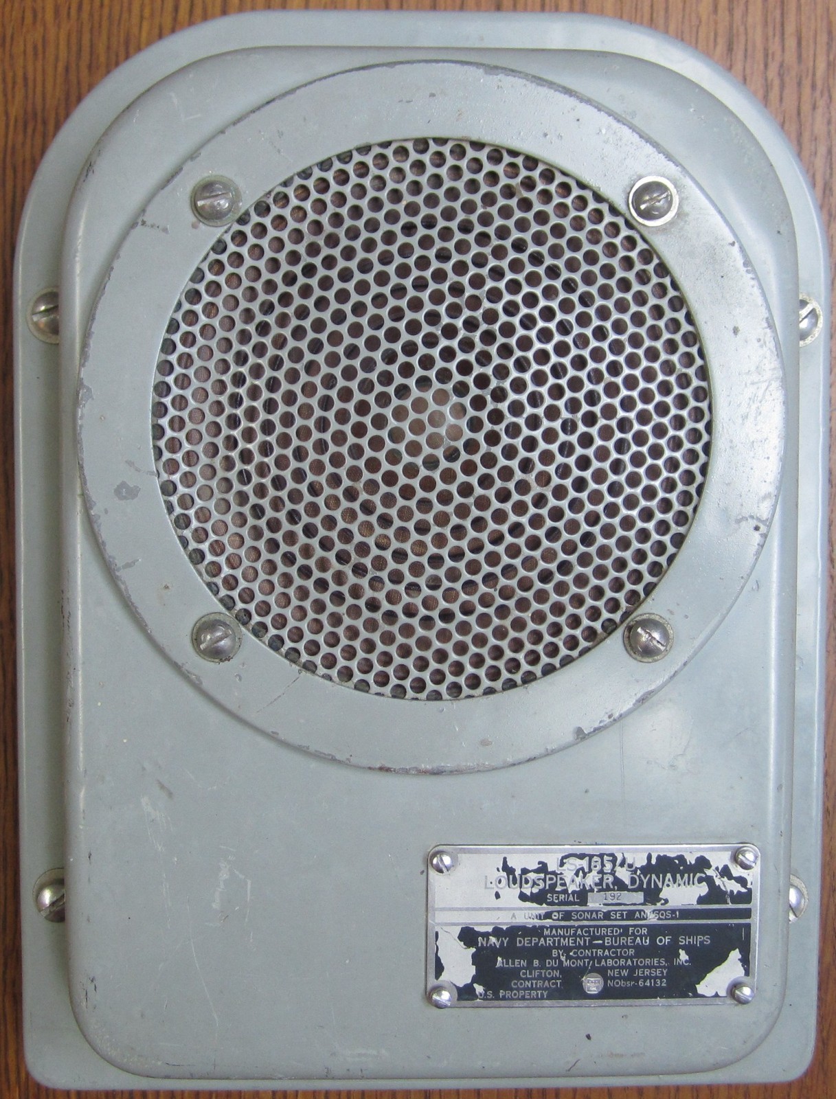
|
|

|
|
|
|
manuf Dumont | == |
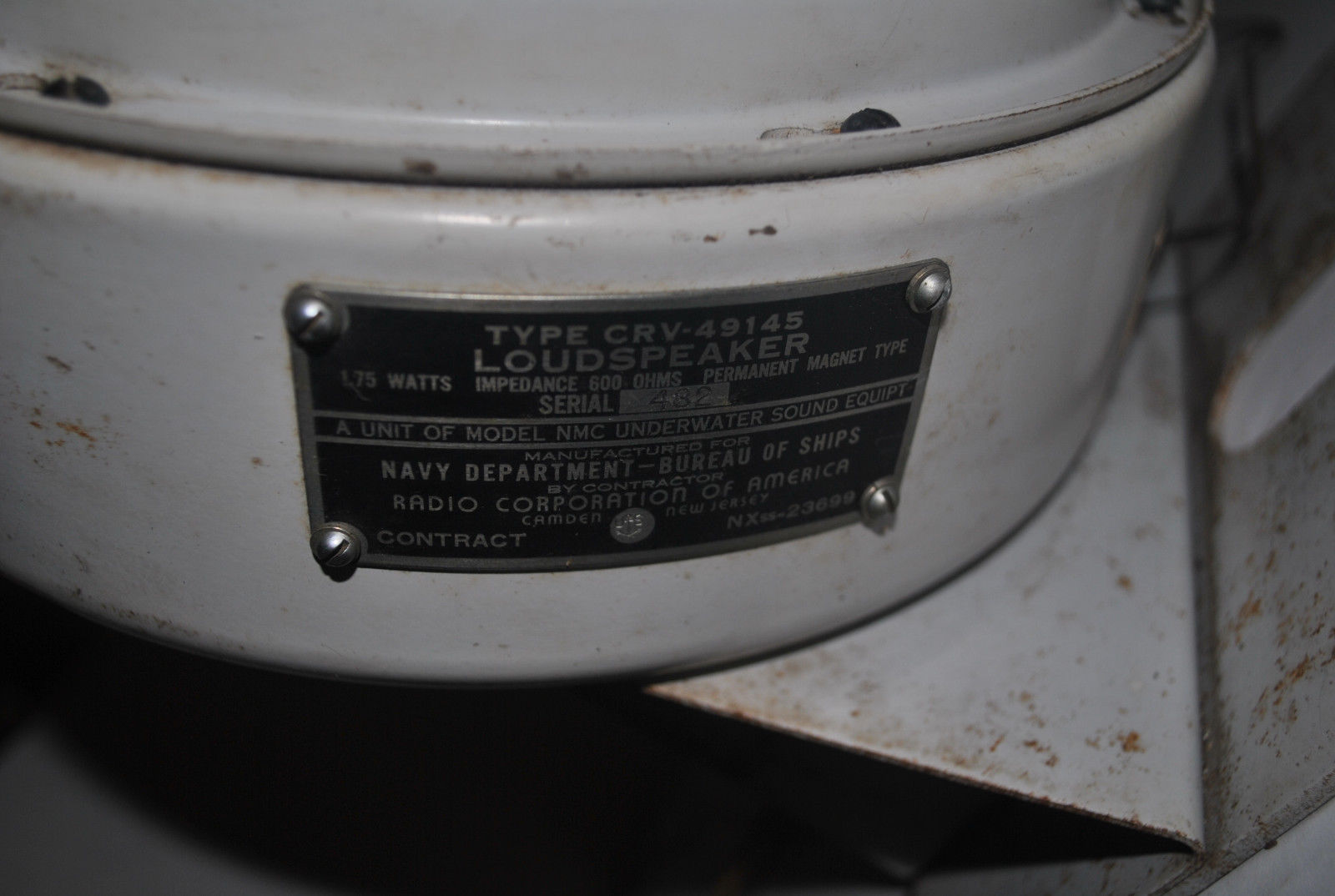
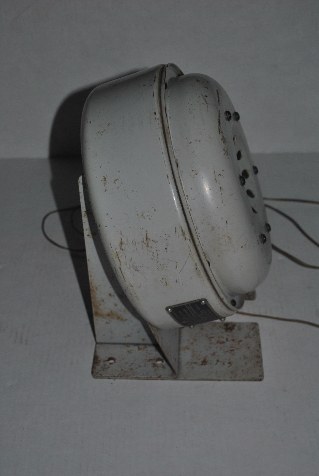
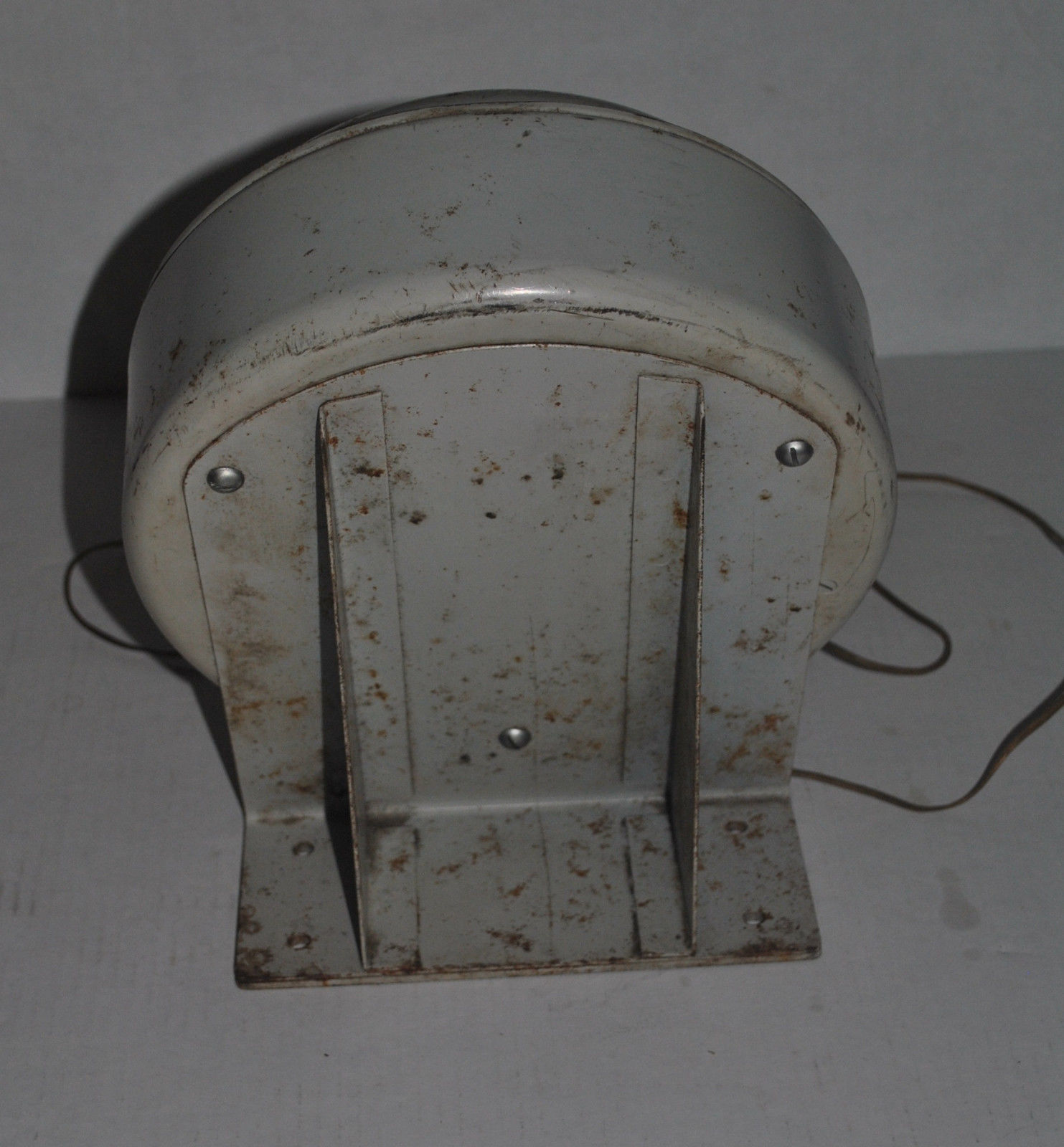
CRV-49145 for NMC equipment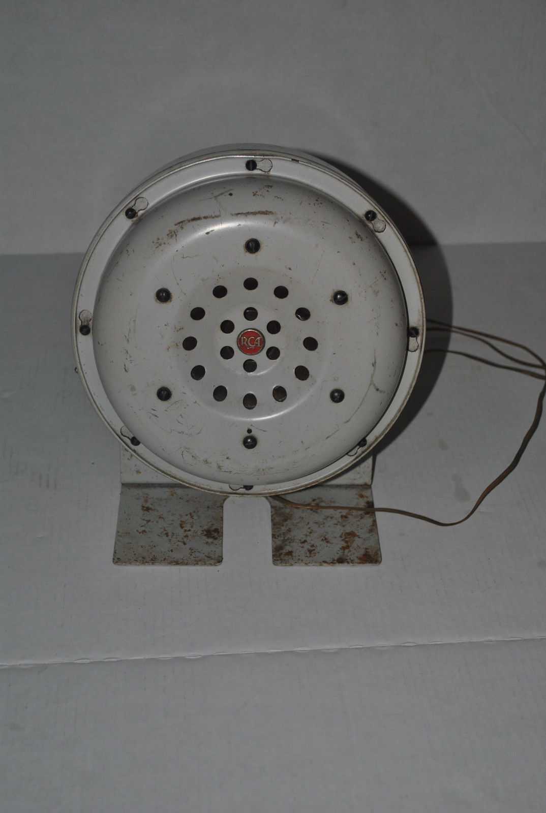
|
|
|
|
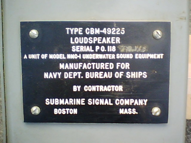
CBM-49225 for NMC-1 equipment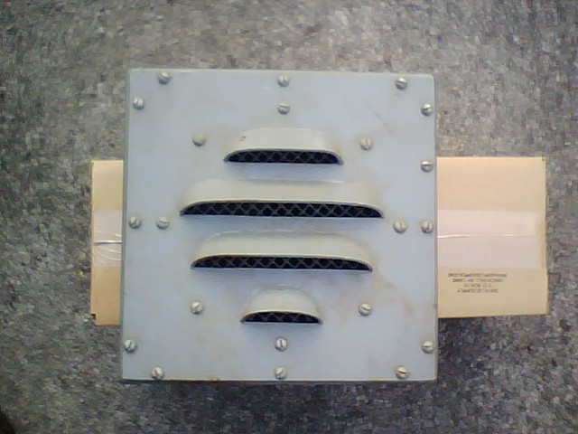
|
|
== | == |
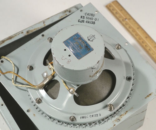
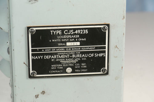
CJS-49235 for QJB Sonar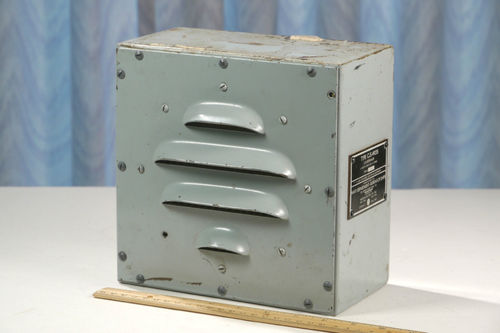
|
|
|
== |


