AN/URT-3 RF Oscillator - Restoration Page 2
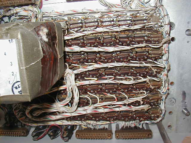
The RFO is a tube-type frequency synthesizer based on multiple oscillator,
multiplier, divider, and mixer modules. The frequency can be set with 10 cps
resolution either manually by 7 knobs (XX.XXX XX0 Mc) or remotely by dialing up
one of 10 channels, each set with 7 miniature rotary switches.
Switch wafers within the modules are activated by Ledex rotary actuators,
advancing one switch position per pulse. The actuator keeps pulsing until the
switch shaft gets to the position it is seeking. The manual knobs are on the
same shafts as 7 of the 21 Ledex units - the knobs are used for manual control
and the Ledex actuators for remote control. The other 14 actuators are slaved to
the 7 masters - turning a knob may make 4 or 5 other Ledex units start seeking a
new position. All in all, it is a marvelously complex design! (Note - the
closely related AN/SRT-14 design does not have remote control so knobs and
module switch shafts are slaved together with multiple small "bicycle
chains")
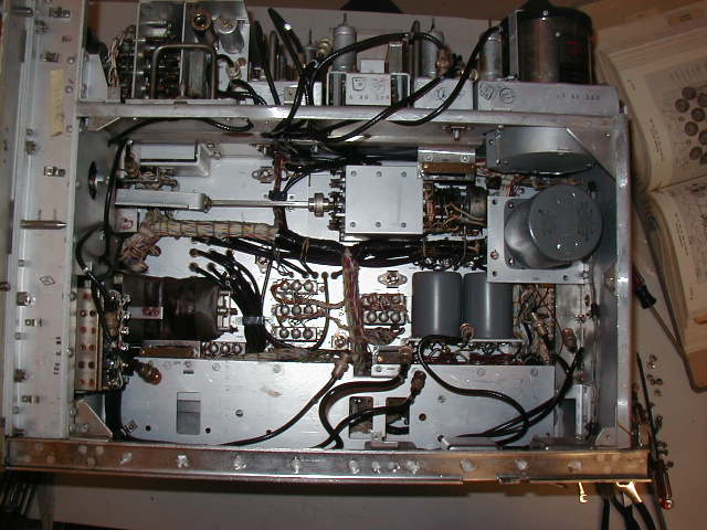
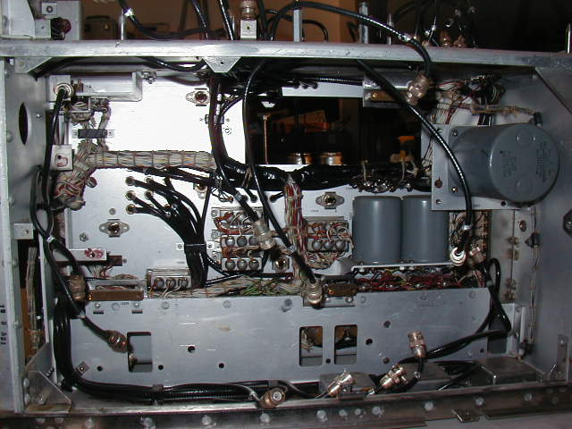
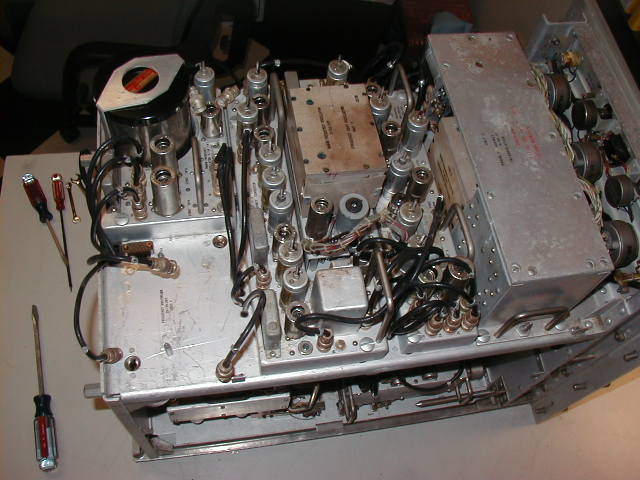
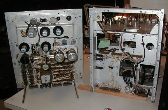
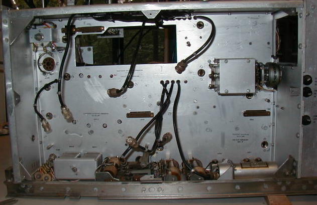
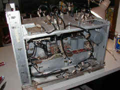
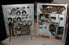
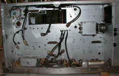
The RFO is built around a central chassis with removable modules mounted on
right, left, top, & bottom sides. The front panel is also removable. This
page shows removal of the modules for cleaning. RFO page 1
shows the initial cleanup of piles of mouse poop on the top of the unit. This
page shows removal of the modules for access to the main chassis. RFO
Page 3 shows cleaning and reassembly.
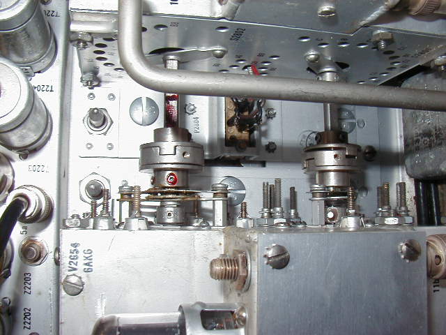
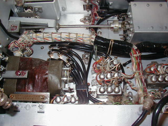
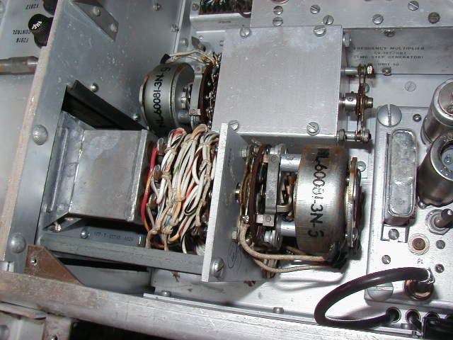
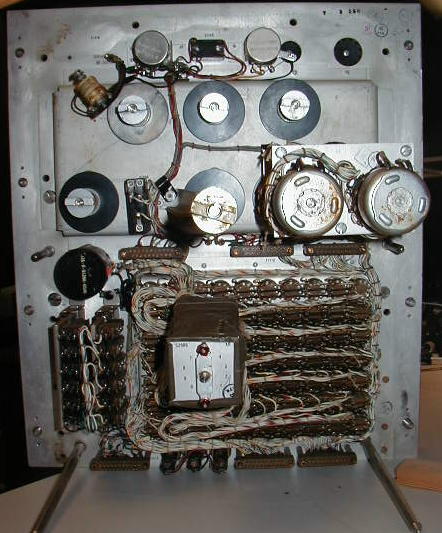
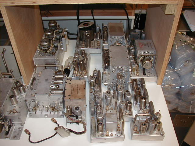
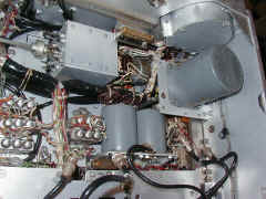
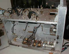
RIGHT SIDE
|
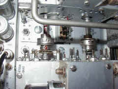
right side module shaft couplers |

right side module shaft couplers |
right side Ledex rotary actuators |
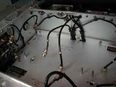
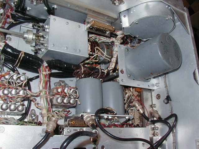
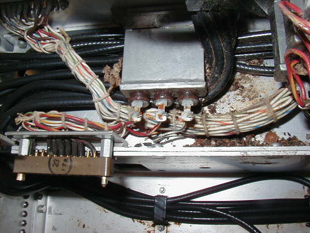
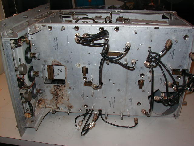
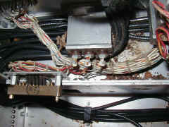
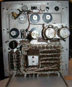
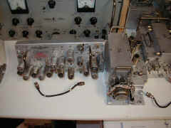
Right side modules removed to access interior cover. |
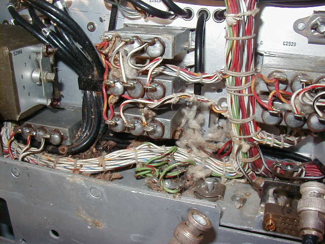
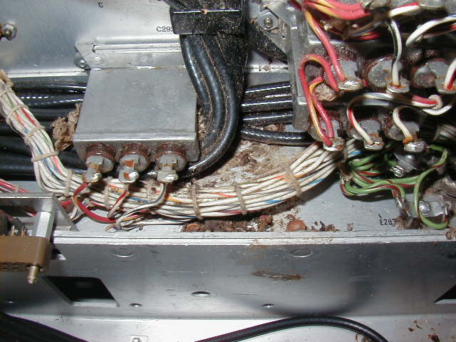
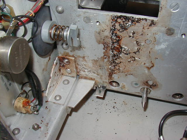
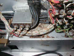
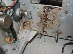
Right side interior cover removed -
Another mouse nest! |
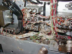
Right side interior cover removed
-
Another mouse nest! |
Right side interior cover removed
- |

Right side interior cover removed
- |
Right side interior cover removed
- |
 |
 |
|
 |
 |
 |
|
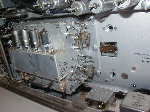
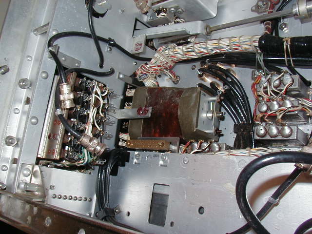
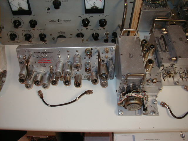
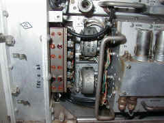
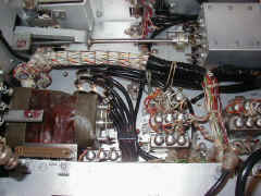
LEFT SIDE
|
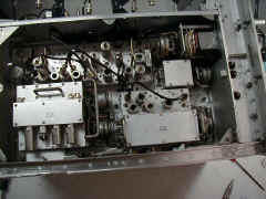
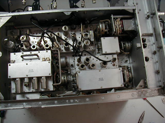
Left side modules |

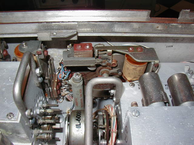
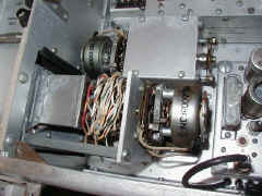
remote dial-up stepper switch |
Ledex pulser motor/switch at top |
 |
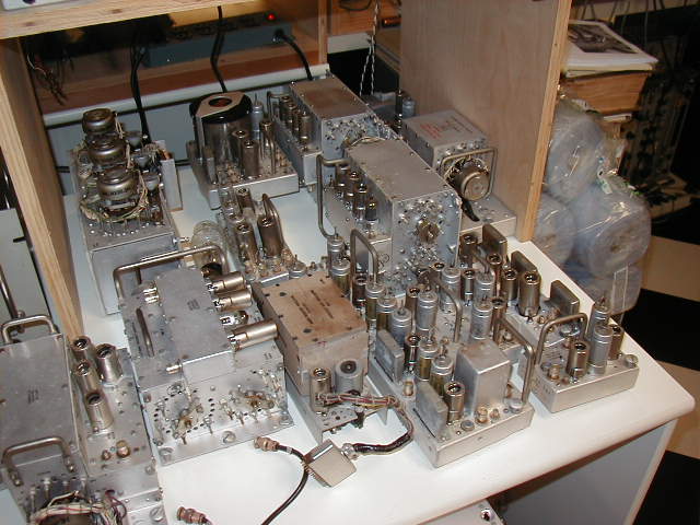
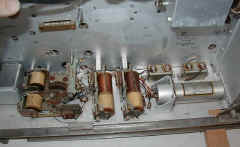
TOP
|
Top modules |
after removal |
cleanup needed |
|
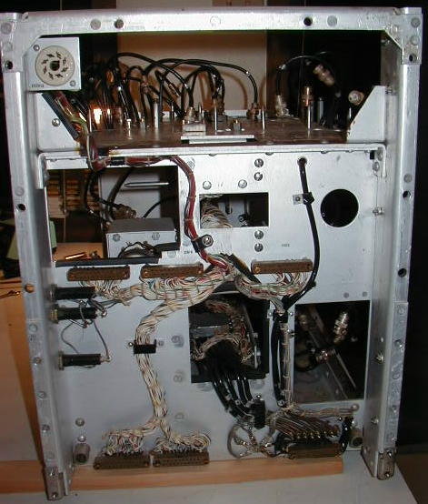
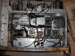
FRONT PANEL
|
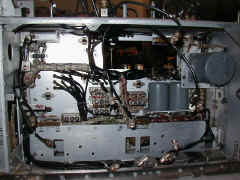
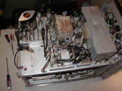
Front Panel removed |

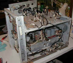
Chassis behind front panel |
front panel and chassis |
remote frequency select switches -
10 channels XX.XXX XX0 Mc |
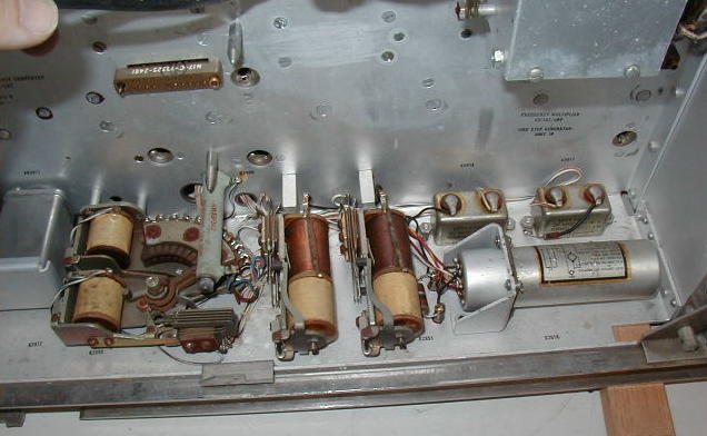
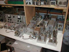
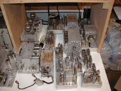
Modules awaiting cleaning
|
 |
 |
 |
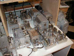 |
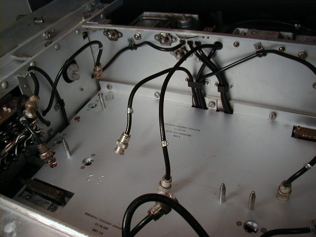
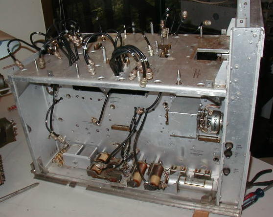
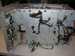
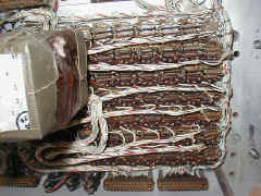
Chassis awaiting cleaning
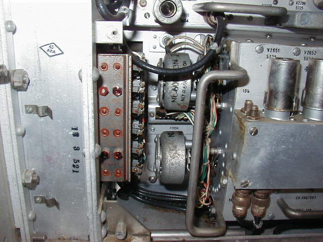
|
Right side & Top |
Top & Left side |
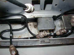
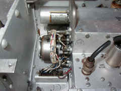
Left side - coax switch box is not removable |
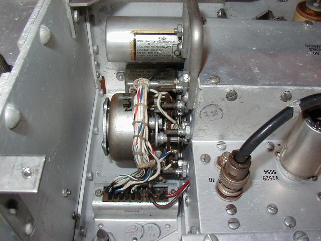
Left side - channel stepper and Ledex pulser |
| |
|
|
|