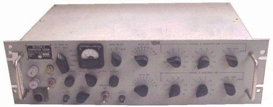
Spectrum Analyzer Equipment
AN/GRM-33 Single Sideband Analyzer Set (TMC PTE)
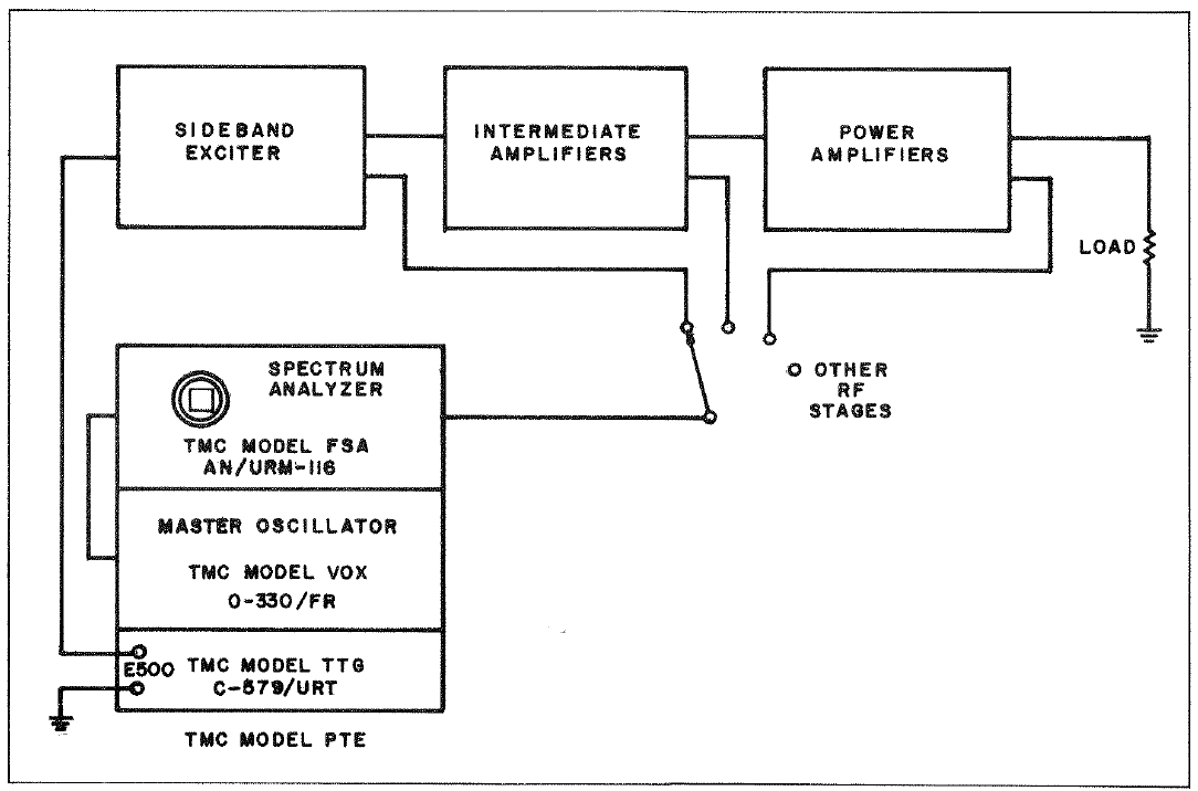
TMC Model PTE, -1, -2, -3, -4
Includes
- AN/URM-116 Spectrum Analyzer
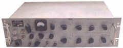
- O-330/FR Master Oscillator (TMC VOX)
- O-579/URT Two-tone generator
(TMC TTG)
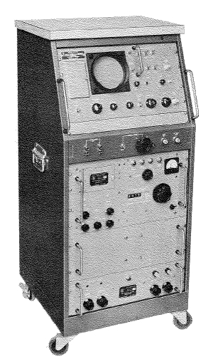

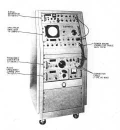
AN/URM-135A Spectrum Analyzer Set
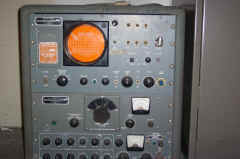
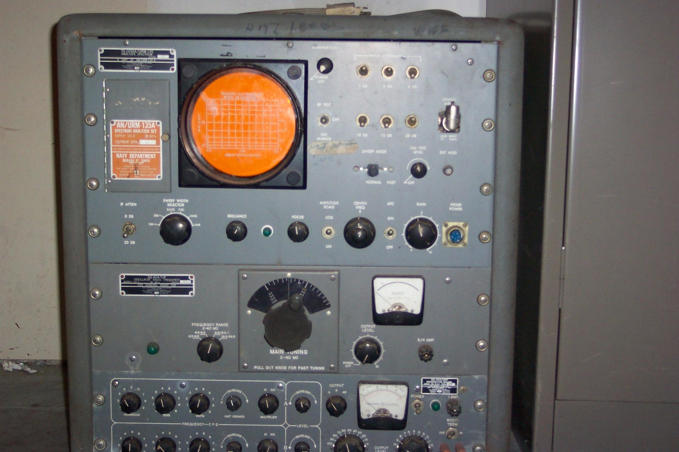
2-40 mc center freq.
150cps-14kc sweep width
. Includes:
- TS-1456A/URM-135 analyzer
- SG-404/UR 2-40 mc tuner
- SG-403/URT two-tone AF generator
Please let me know if you have a manual for the complete URM-135A or any of the other components
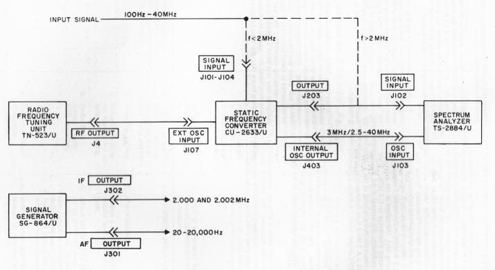
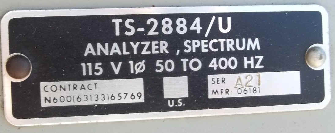
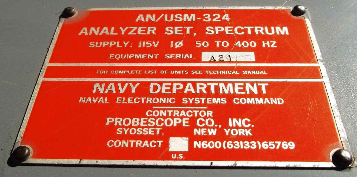
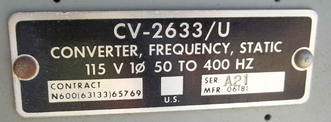
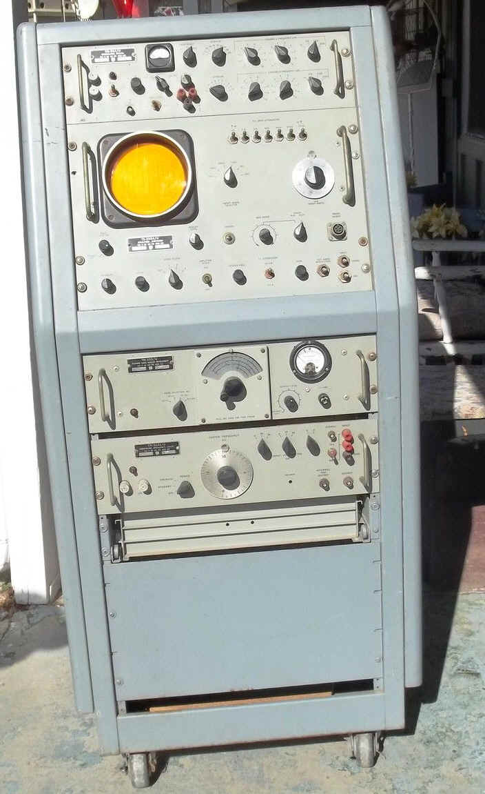
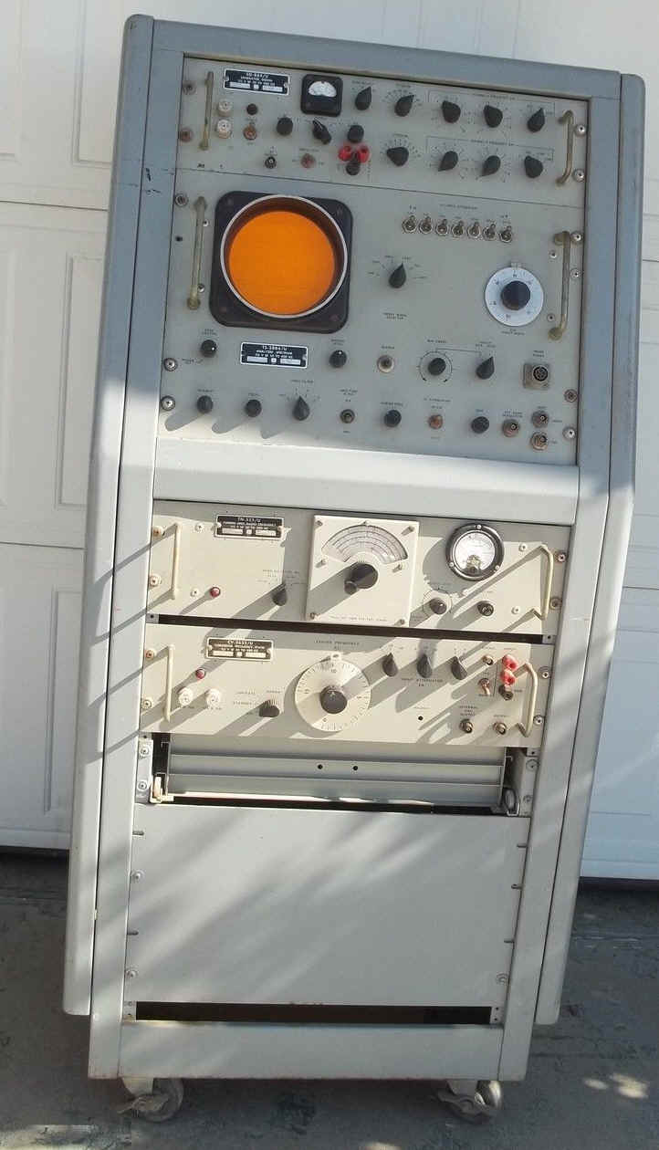
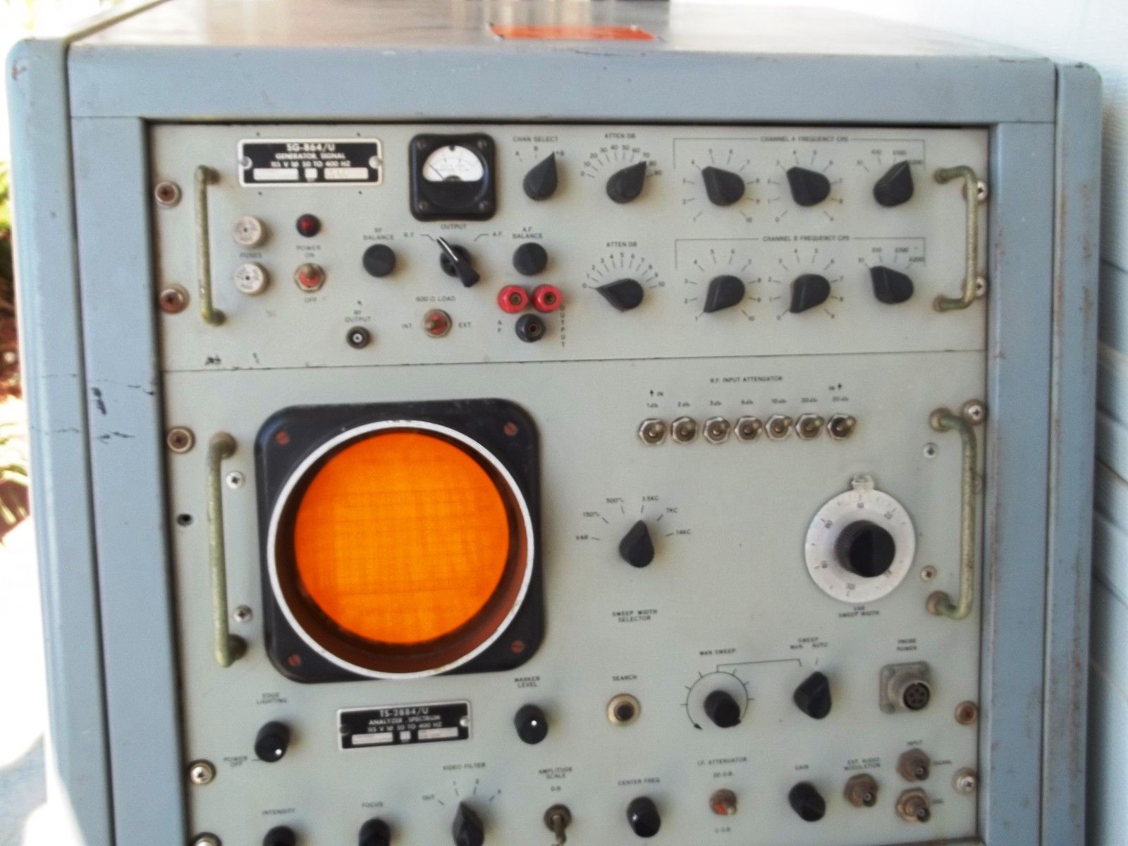
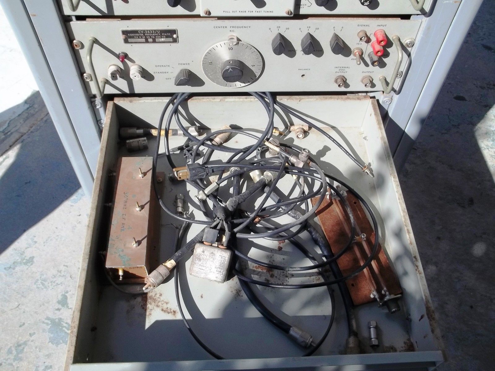
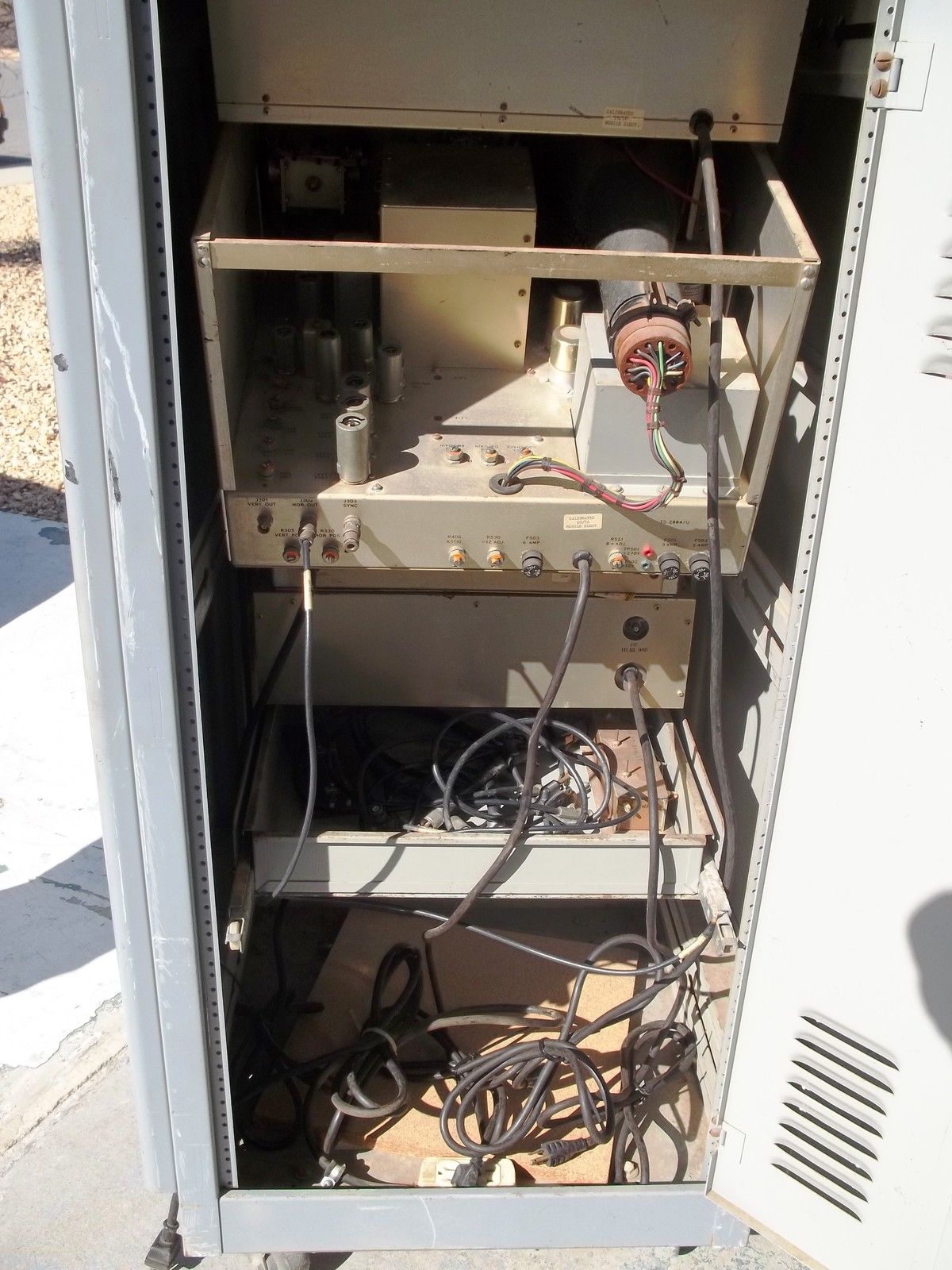
AN/USM-324 Spectrum Analyzer Set
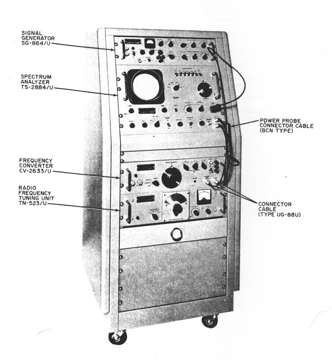
100cps-40 mc center freq.
150cps-14kc sweep width
- TS-2884/U Spectrum Analyzer
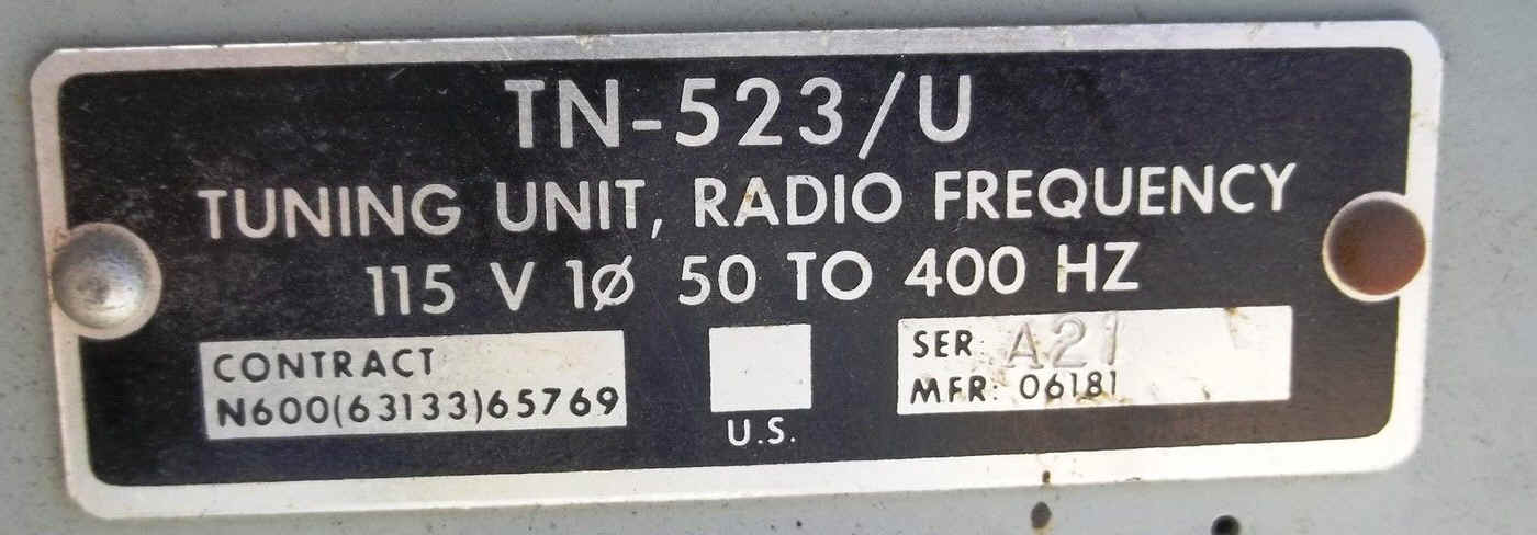
- TN-523/U 2-40 mc tuner
- CV-2633/U converter (100 cps-2mc)
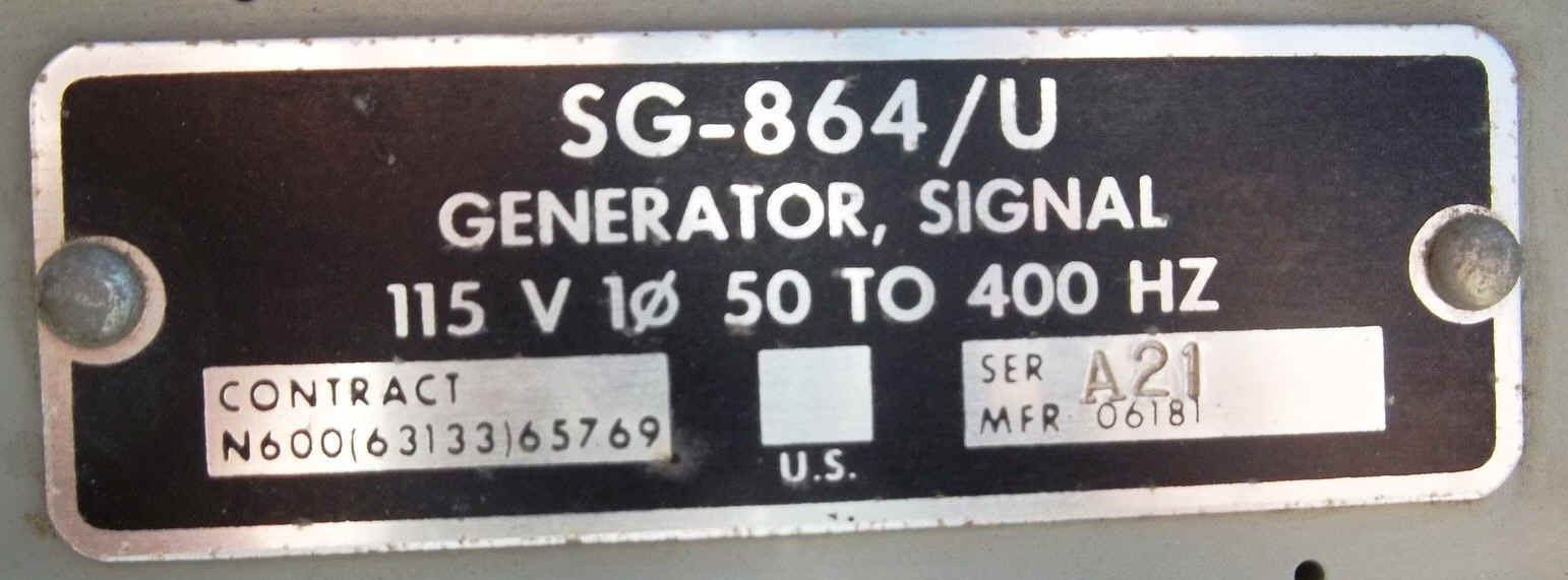
- SG-864/U two-tone AF/RF generator
See individual component manuals for schematics, parts, etc.
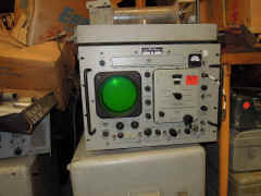
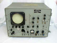
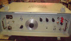
TS-1379/U Spectrum Analyzer

manuf by Intercontinental Instruments
equip. available from www.fairradio.com
Manual available from www.vintagemanuals.com
-
(NOT the same as TS-1379A/U manual)
485-515kc
2mc-31.5mc
100cps-2mc with CV-2353/U or CV-2353A/U
Sweep Width
150cps-30kc
manual NAVSHIPS 0969-246-4010
TS-1379A/U Spectrum Analyzer
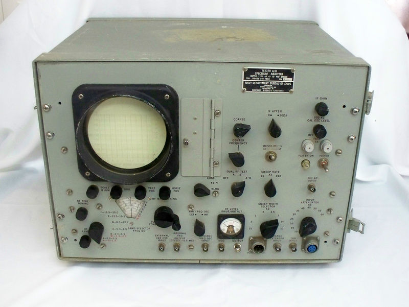

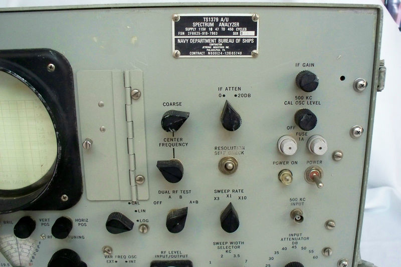

485-515kc
2mc-30mc
100cps-2mc with CV-2353A/U
150cps-30kc
- download here
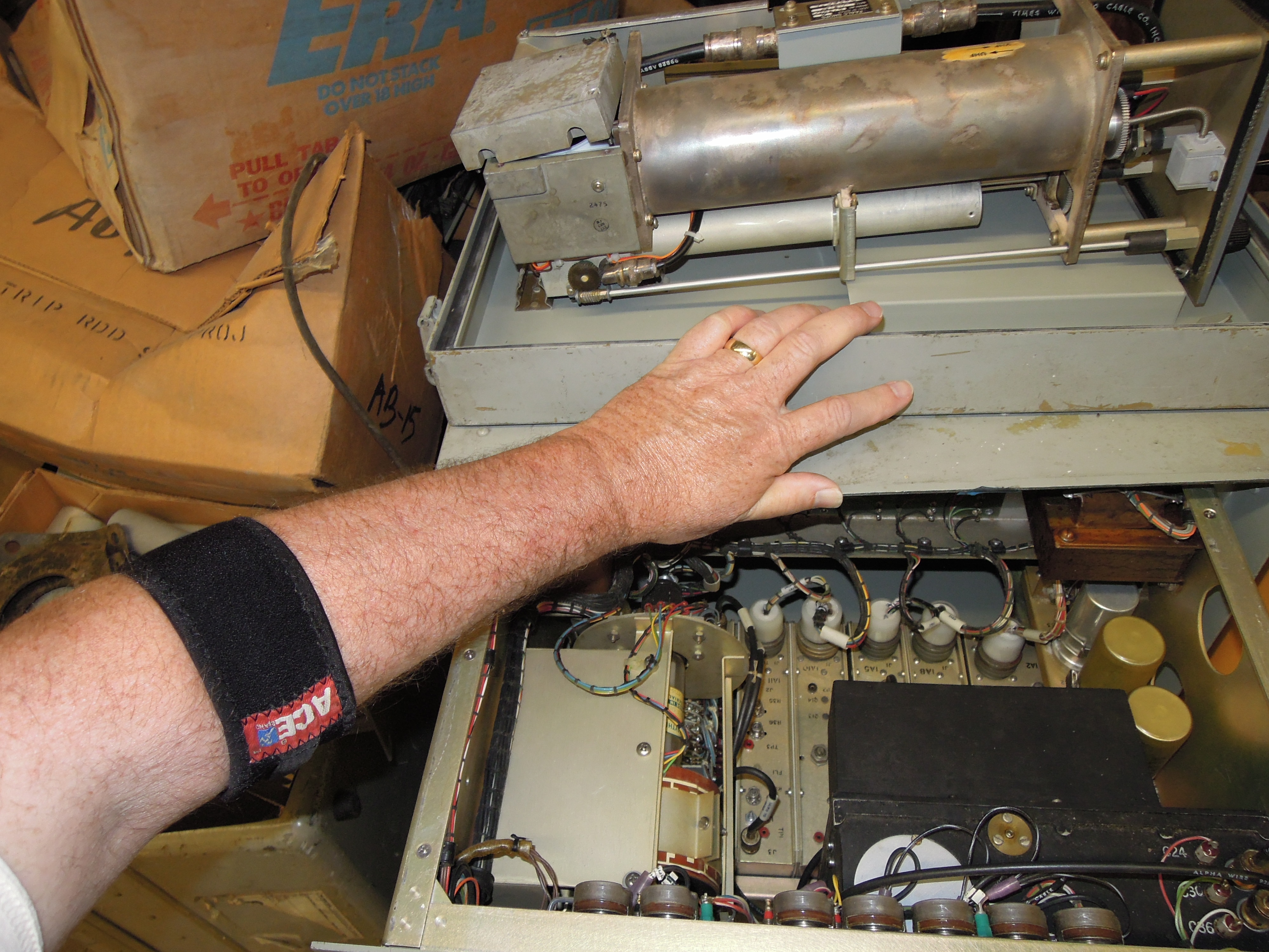
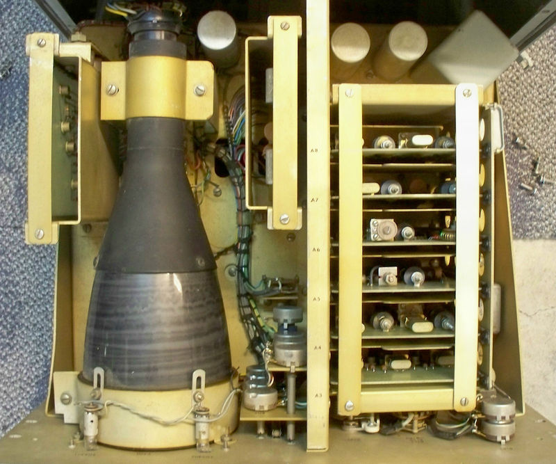
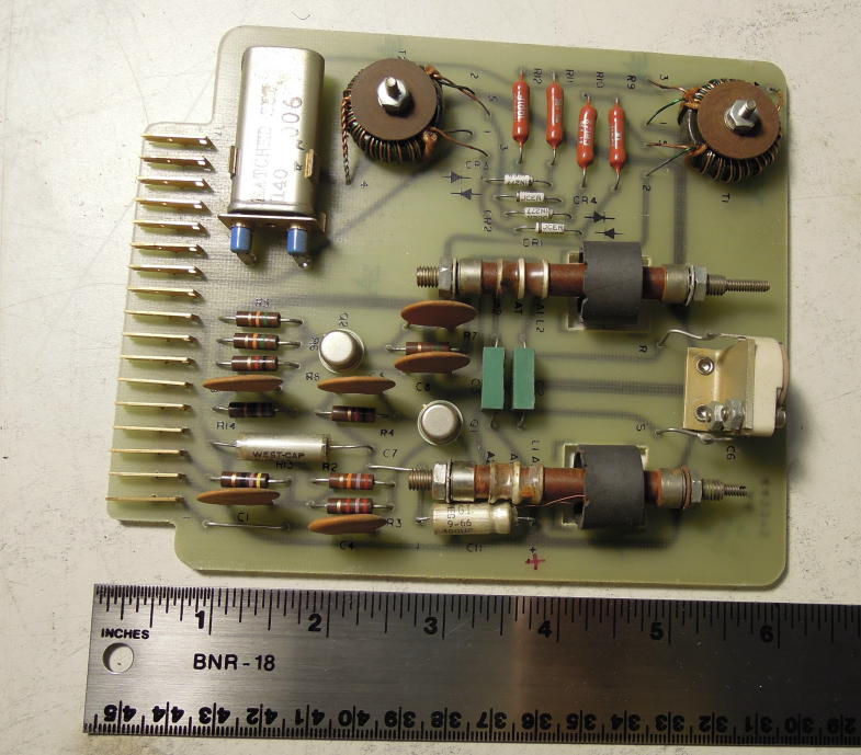
WANTED - board A4 or A6 for TS-1379A - Please help!
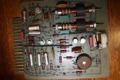
A4 board needed to restore my TS-1379A
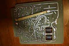
A4 board - reverse side
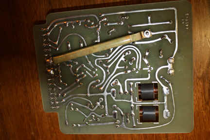
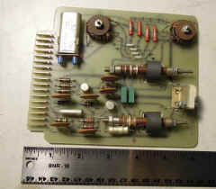
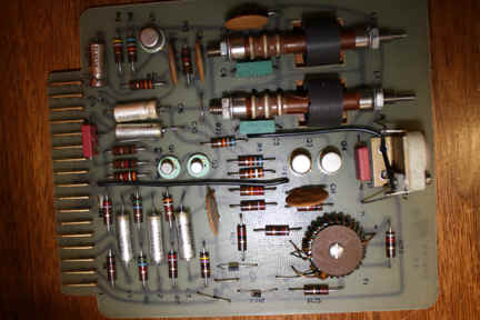
A6 board - it has the same coils and I could use them to make
an A4 board.
The Spectrum Analyzer permits analysis of one or many signals simultaneously, Each signal within the band scanned (sweep width) is displayed on the CRT element as one of a series of "pips". The pip amplitude indicates the signal level. The pip position along the horizontal axis indicates the signal frequency.
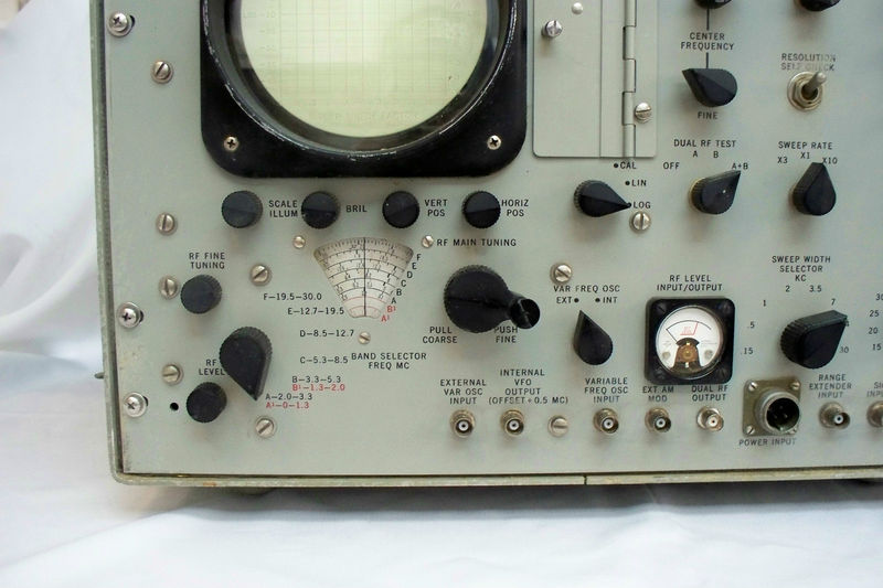
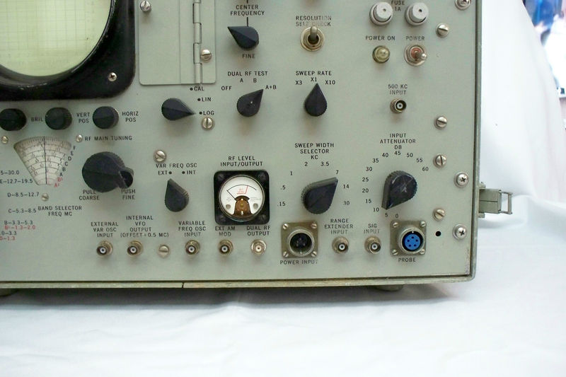
Any one of six parts of the RF band - the "Band Scanned" - within the 2mc - 30mc range of the Analyzer may be selected by means of the Band Selector tunable oscillator, and the "Scanning Width" may be selected by the Sweep Width Selector. The Sweep Width Selector positions provide eight different degrees of frequency separation of the signal display. A preset operating mode automatically adjusts Sweep Width, Gain, Resolution, and Scanning Rate at each one of the Sweep Width positions.
The Band Selector tunable oscillator is a high stability continuous tuning signal generator designed to provide local injection signals over the frequency range of 2. 5mc to 30mc. It is a fully transistorized, precision, variable capacitor tuned oscillator. The 0. 3 volts rms output signal is the first local oscillator in the heterodyne system. The tunable oscillator is free from spurious signals, hum and noise are suppressed at least 60db below signal level. The unit is particularly suitable for use in intermodulation testing.
The Spectrum Analyzer is also valuable for monitoring a frequency band for the appearance of or disappearance of and shift of signals. A display of frequency distribution can be obtained by selecting the Sweep Width, bringing the "Scanned Band" into the narrowest position (150cps) to enable examination of signals so closely adjacent in frequency that their corresponding "pips" normally are merged together. At this reduced Sweep Width (150cps) signals with an amplitude ratio of 60db separated by 50cps are clearly indicated. One of the internal self-checking features, the Internal Dual Frequency RF Test, simulates such a test.
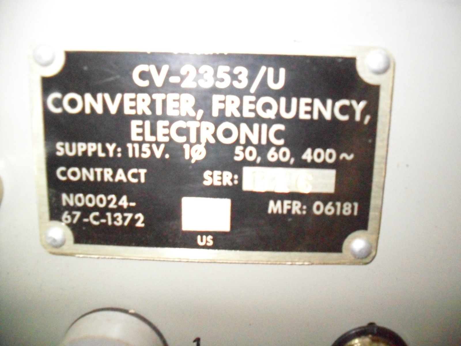
CV-2353/U Frequency Converter
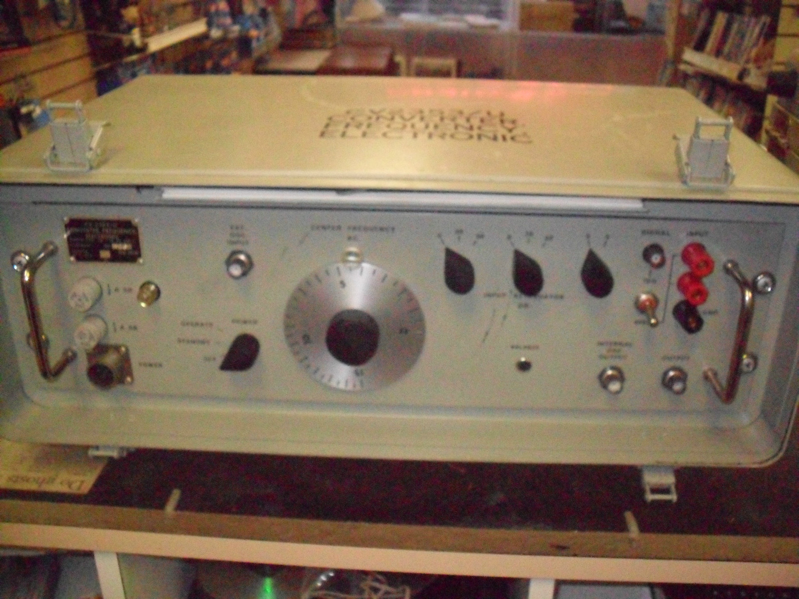
adds 100cps-2mc coverage
(thanks to Elden Meyer)
CV-2353A/U Frequency Converter
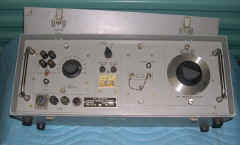
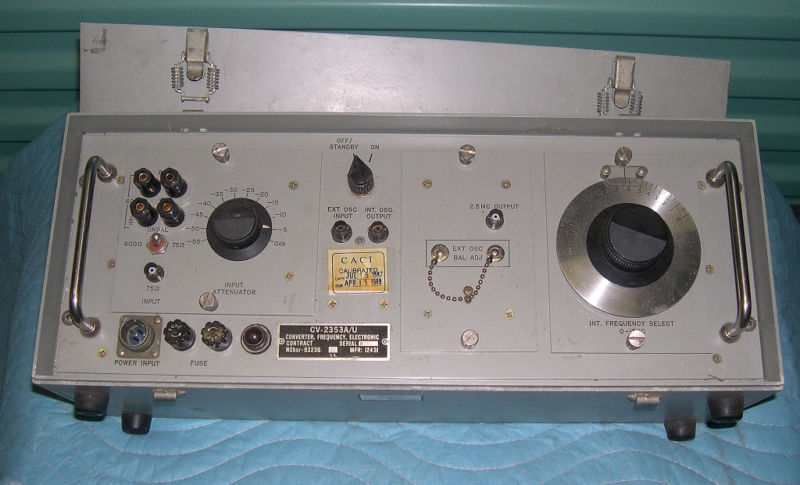
adds 100cps-2mc coverage
Please send e-mail if you have a manual or any info.
Available from www.fairradio.com
See manual for CV-2353 above - not the same, but operation is similar
Two-tone Signal Generators
two-tone AF & RF test generator
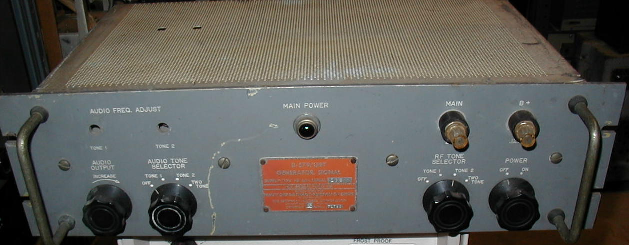
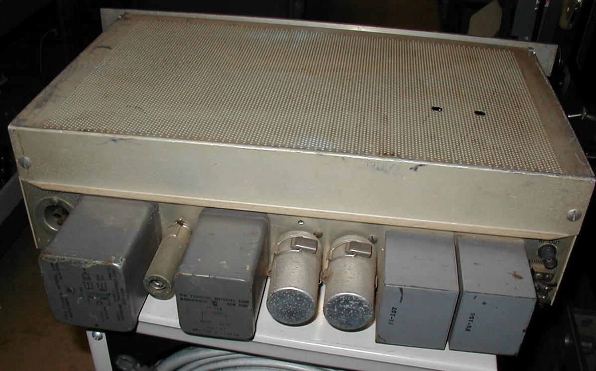
TMC model TTG-2 (O-579A)
manual & spec sheets thanks to K4OZY
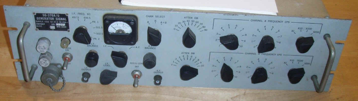
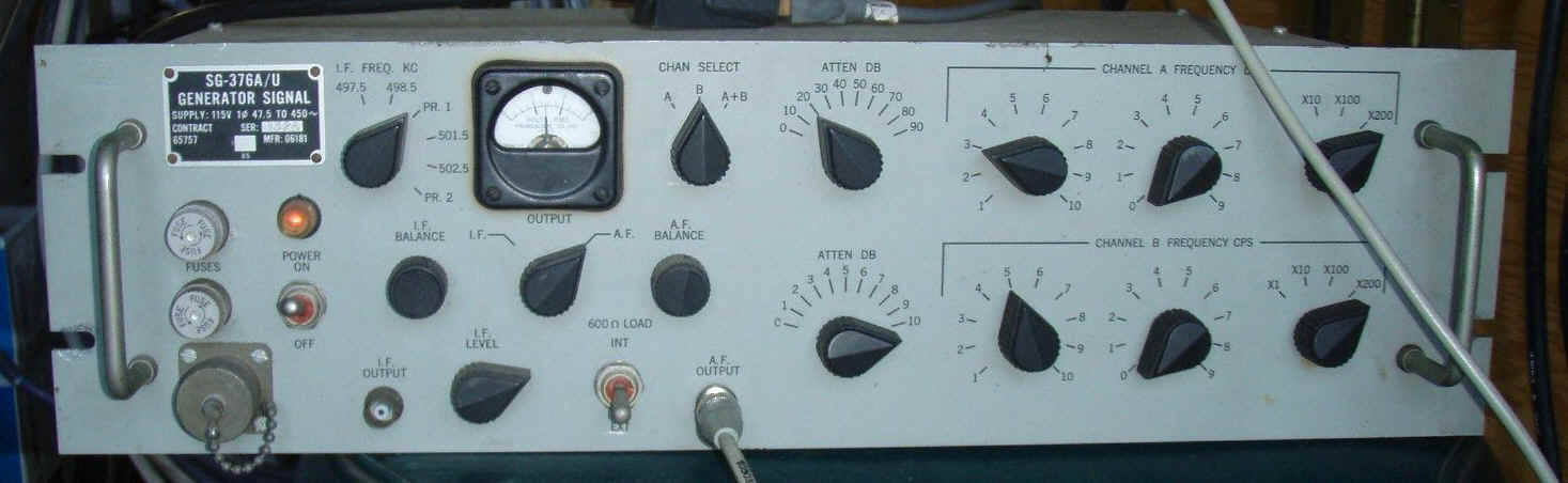
SG-376/U Two-tone test generator
Transistorized two-tone IF Signal Generator for testing SSB equipment. Has two 20 - 20Khz audio oscillators and two independent IF oscillators. IF outputs 497.5, 498.5, 501.5, or 502.5Khz . Output levels 2-2.5 V into 600 ohms (AF); 1-1.25 V into 60 ohms (IF) with attenuation to 100 db in 1 or 10 db steps. The AF and IF signal outputs are independent of each other. Generates two separate AF signals which can be used independently, one at a time, or both can be added for simultaneous use. It also generates four different, unmodulated IF signals which are available independently, one at a time, or in specific pairs simultaneously. Available from www.fairradio.com
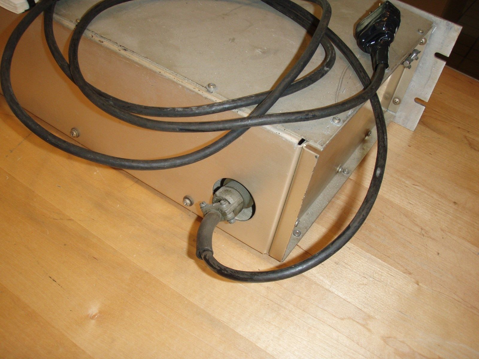
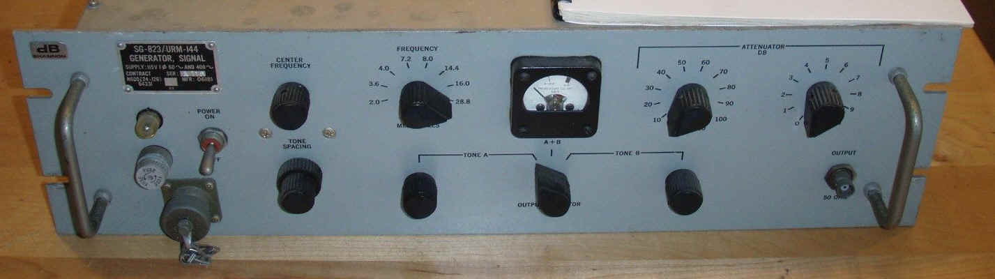
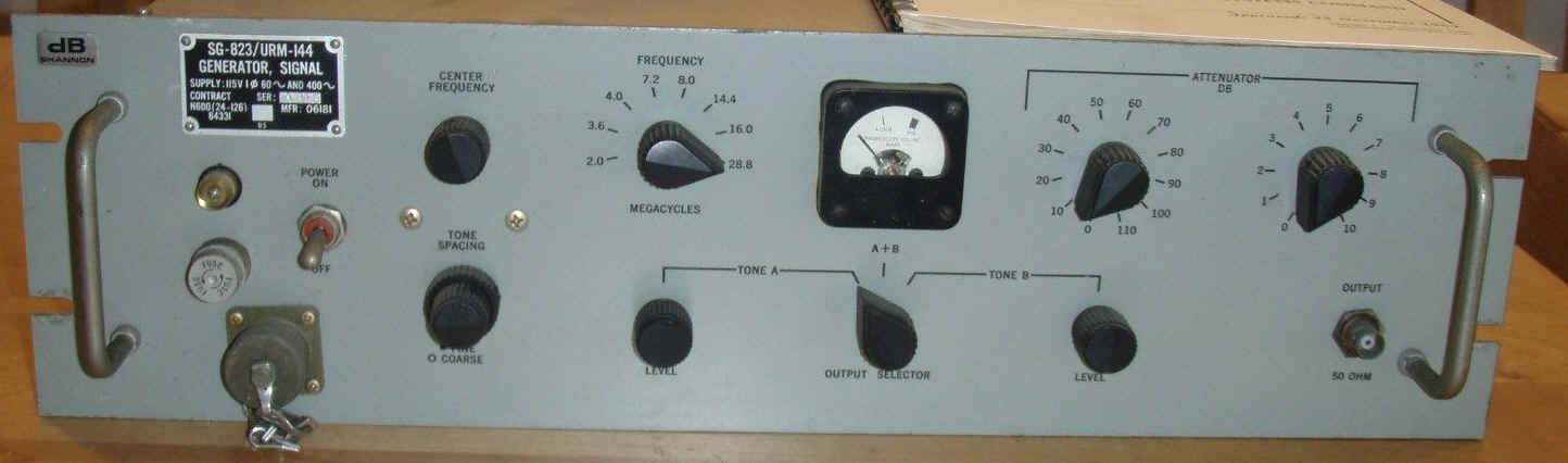
SG-823/URM-144 Two-tone RF generator
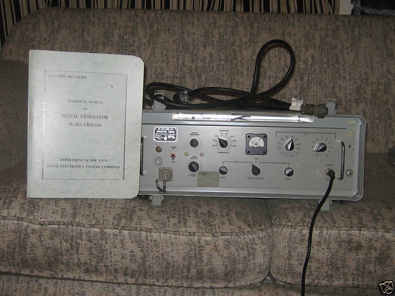
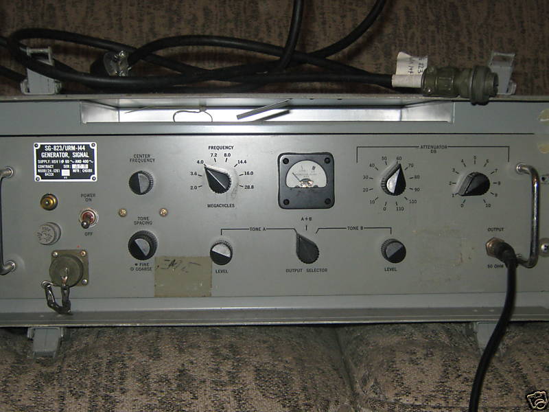
manual available from www.fairradio.com
Also check there for equipment
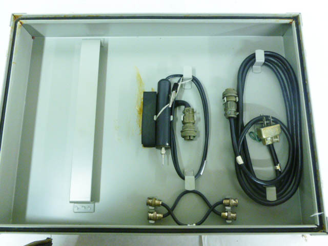
RF Signal Monitors
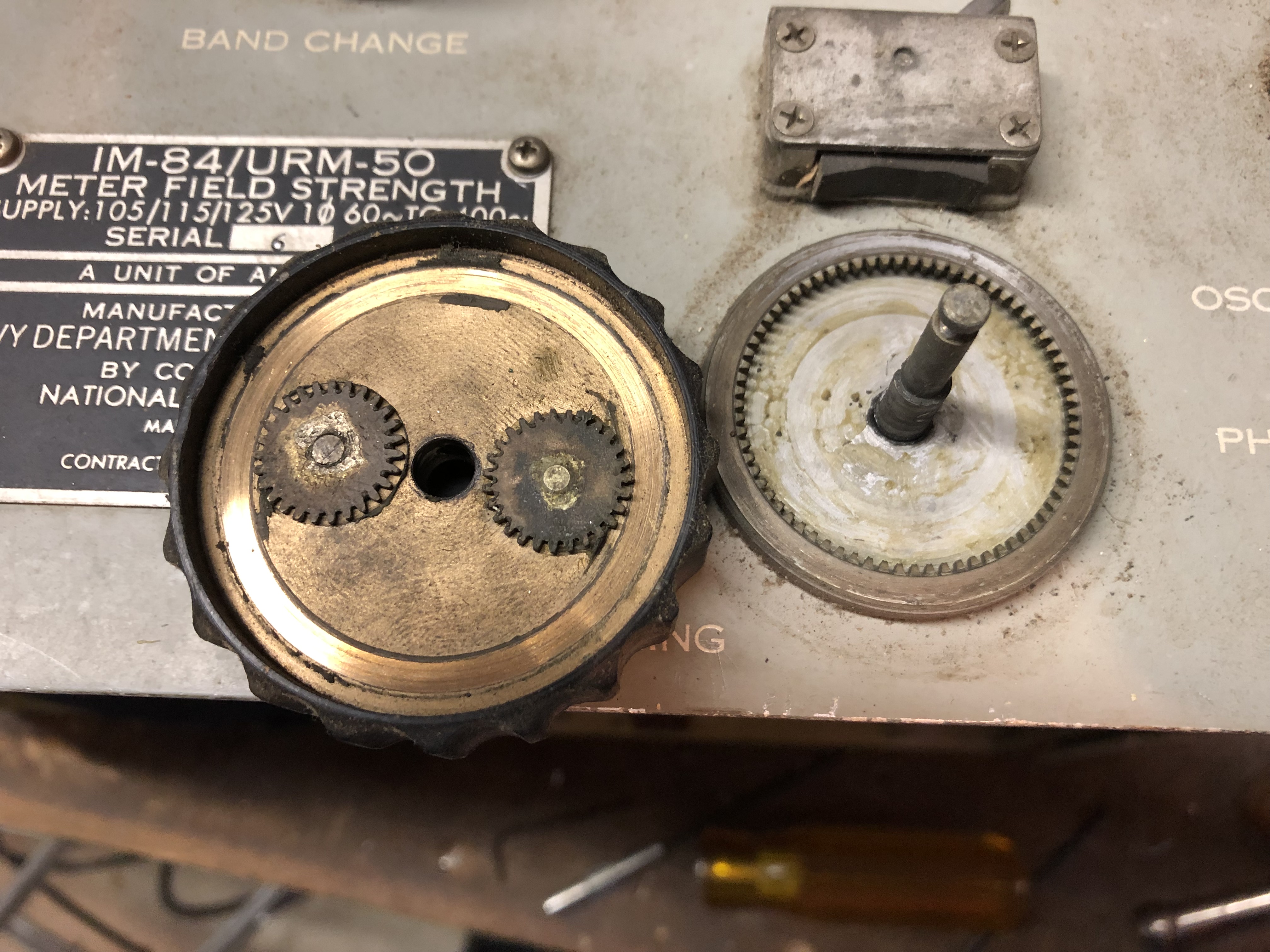
AN/URM-50
Field Strength Meter
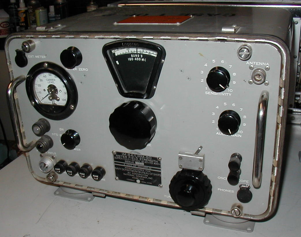
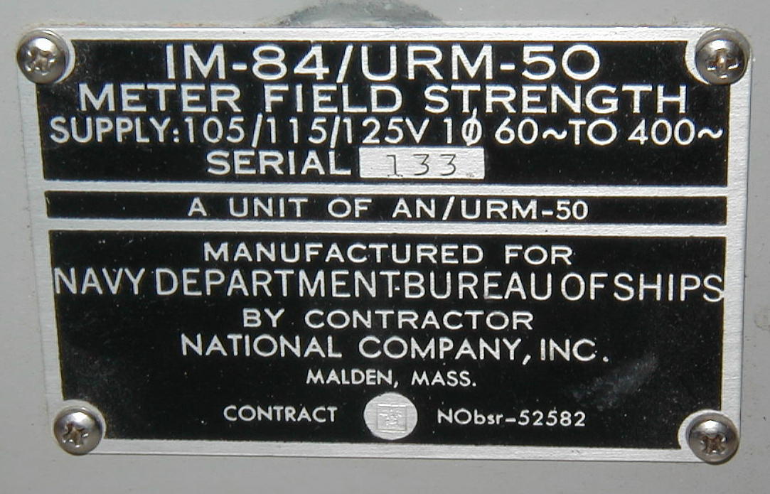
IM-84/URM-50
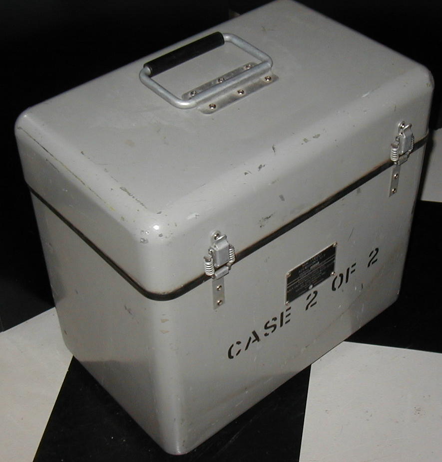
accessory case
used with external antenna or handheld RF sniffer to tune & monitor transmitters
- IM-84/URM-50 FSM
- accessory case
- remote meter
- RF sniffer coil
- mast-mounted antenna
schematic - download 0.3 MB pdf
NAVSHIPS 91946 -
download 28 MB pdf
>>>>>>>>>>>>>>
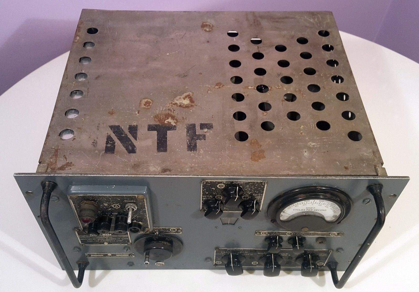
OCT-2 (cabinet)
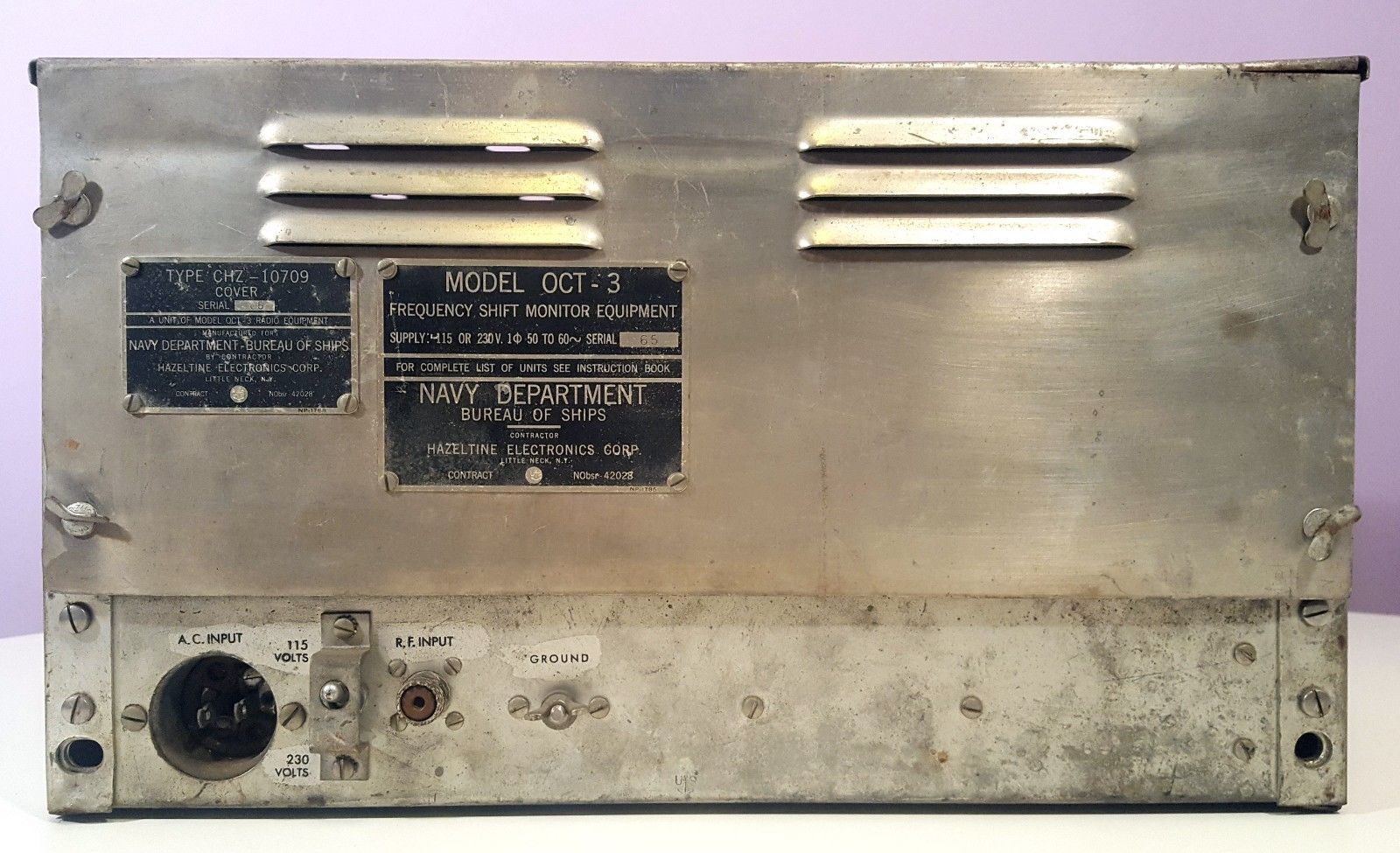
OCT-3 (rack mount)
Frequency Shift Monitor
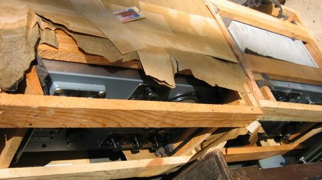
two OCT-3 new in crate -
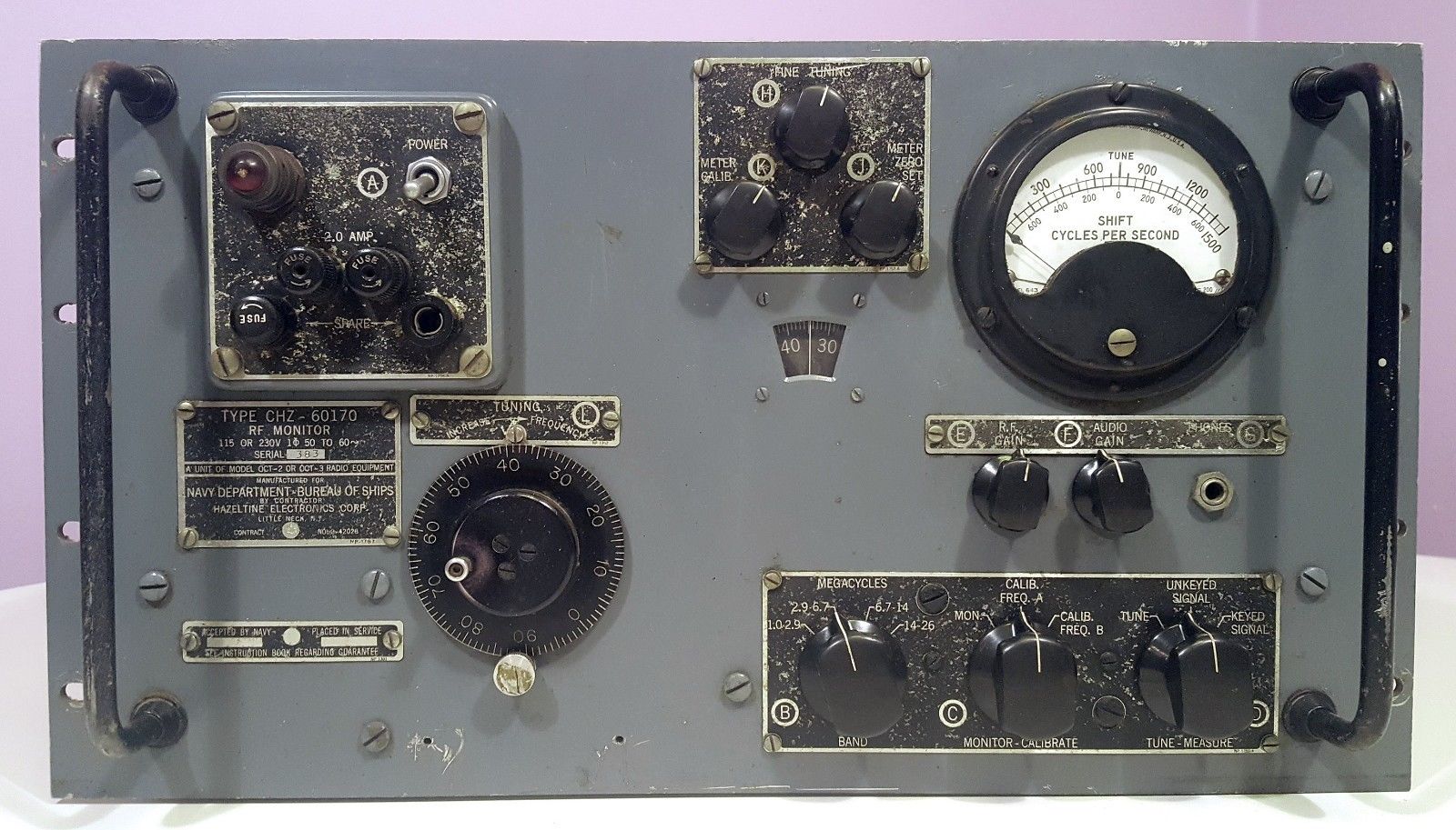
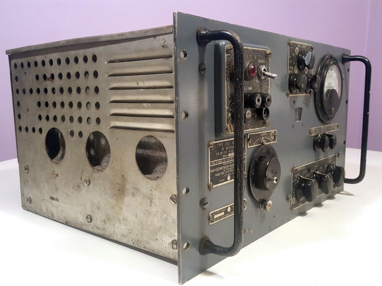
comprises CHZ-60170 receiver
Senses RF in transmitter room or uses external antenna
- see pp 172-173 of "RTTY from A to Z"
OCT-2 (cabinet) and OCT-3 (rack mount) are a 1947 contract. There was an earlier OCT with a different design before this model. It is used to monitor FSK shift in RTTY transmitters. It is basically a superhet receiver with two limiters and a discriminator whose output is supplied to a VTVM which indicates the amount of frequency shift. The audio output (phones) comes from the discriminator to aid in tuning, so it is essentially an FM receiver, not useful for AM or CW.
NAVSHIPS 91131 - download


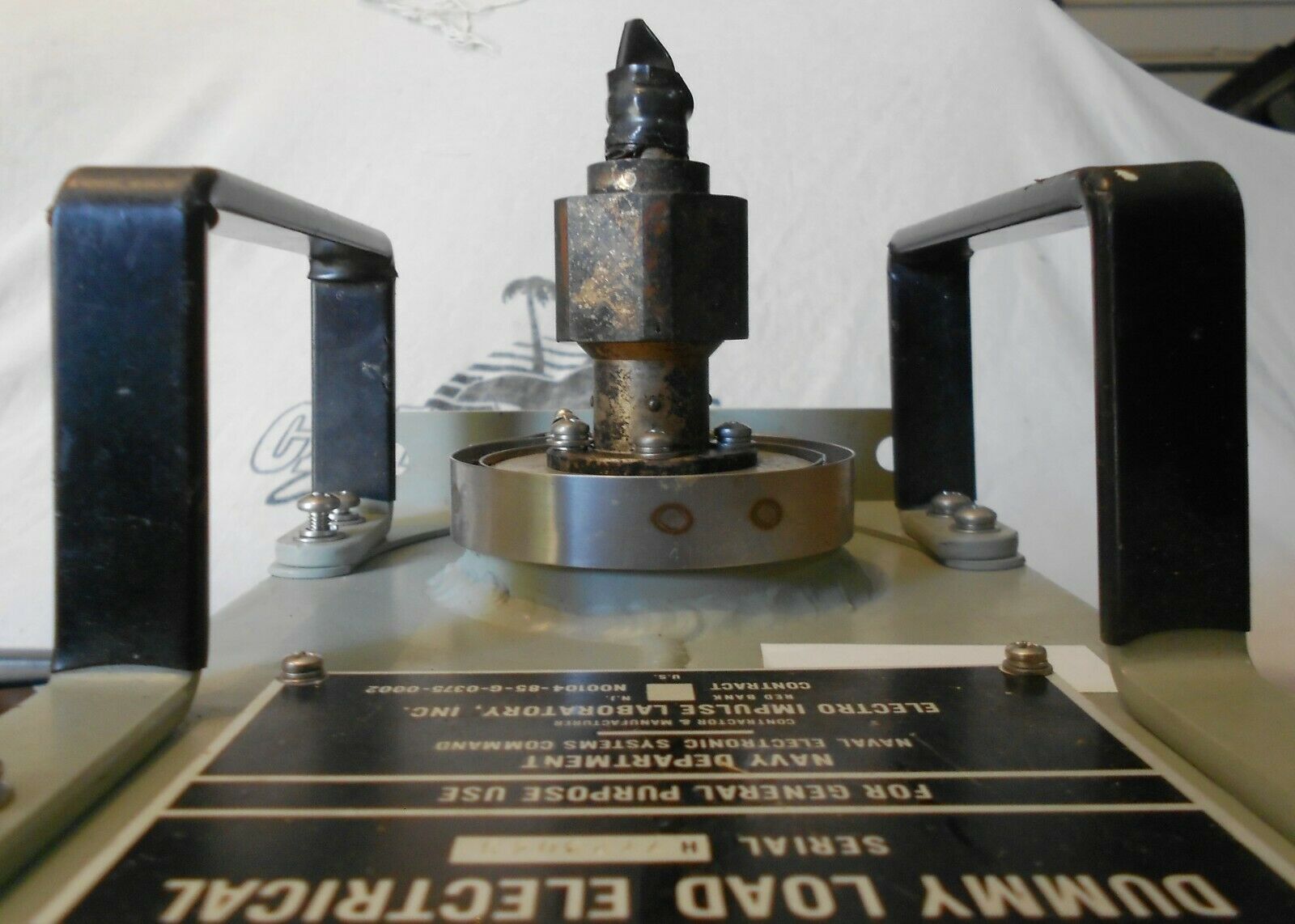
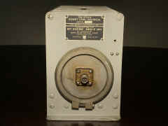
DUMMY LOADS & RF WATTMETERS (DA = Dummy Antenna)
DA-75/U Dummy Load

1000 W
50 ohms
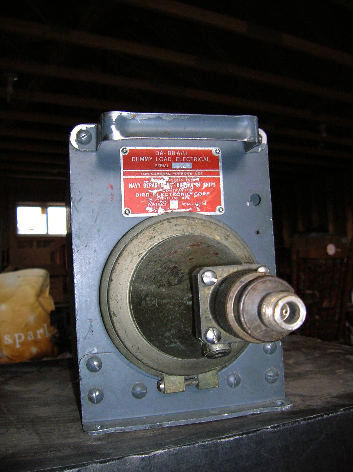
DA-88A/U Dummy Load

50 ohms
DC-4GHz


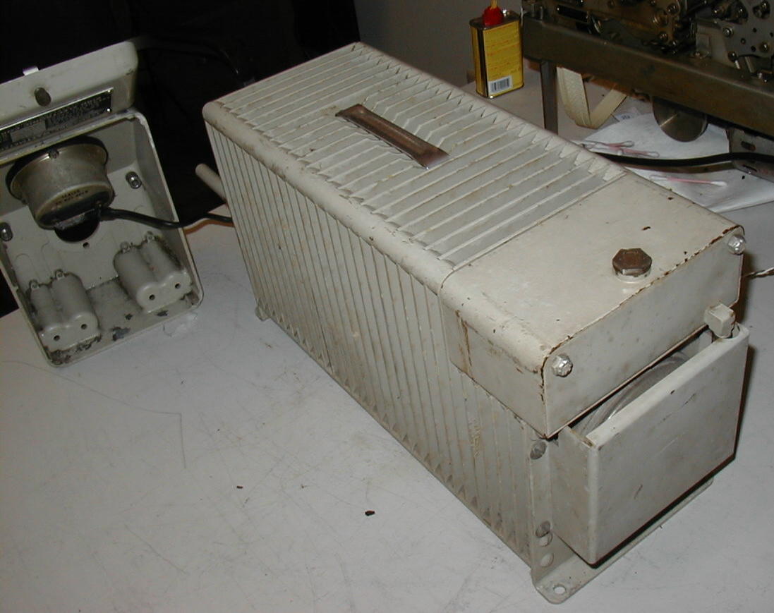
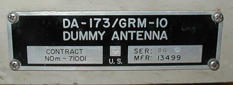
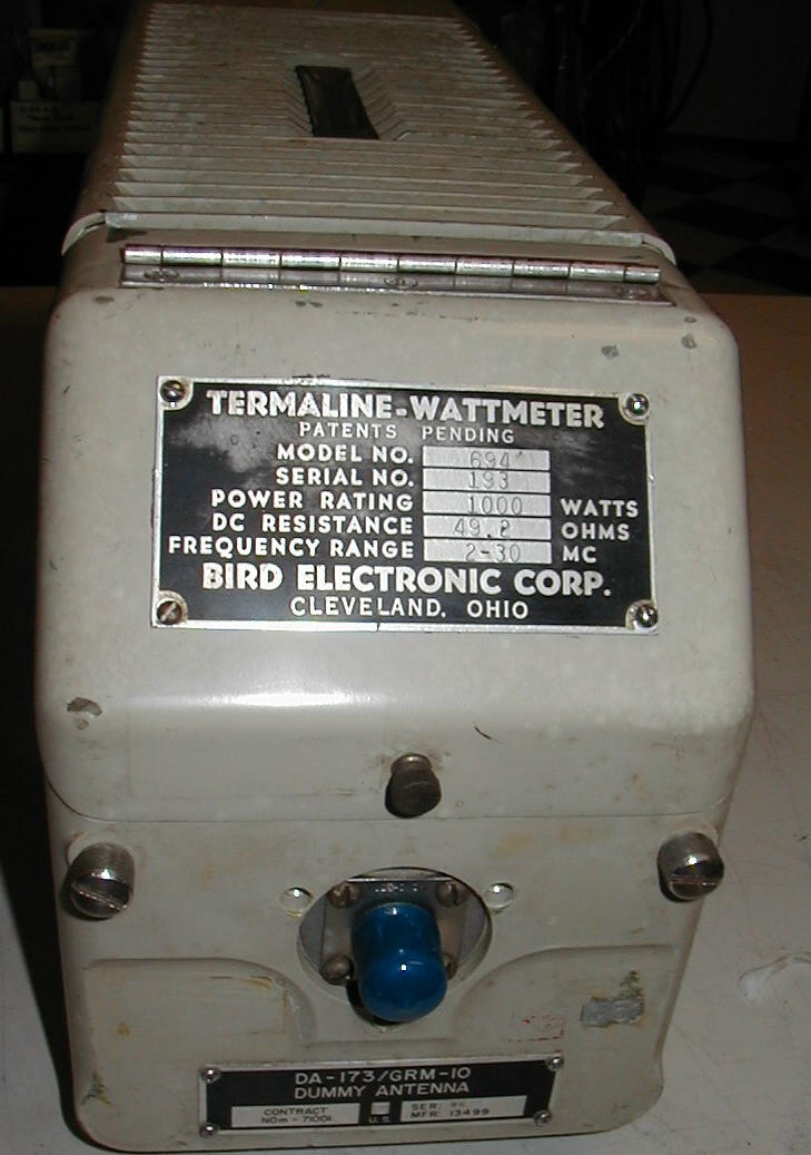
DA-173/GRM-10 Dummy Load & Wattmeter
Bird Model 694
DA-242A/U Dummy Load
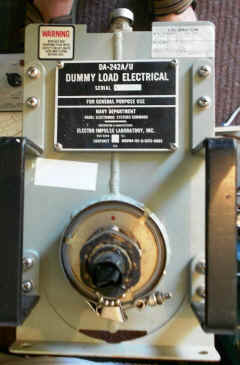

DC-500mc
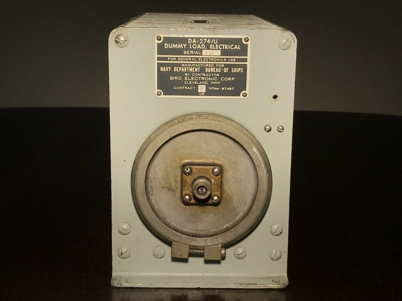
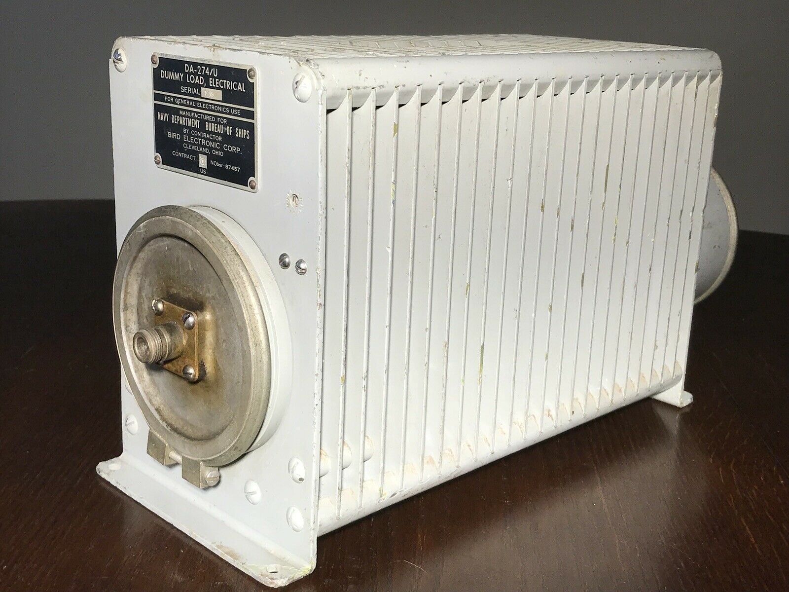
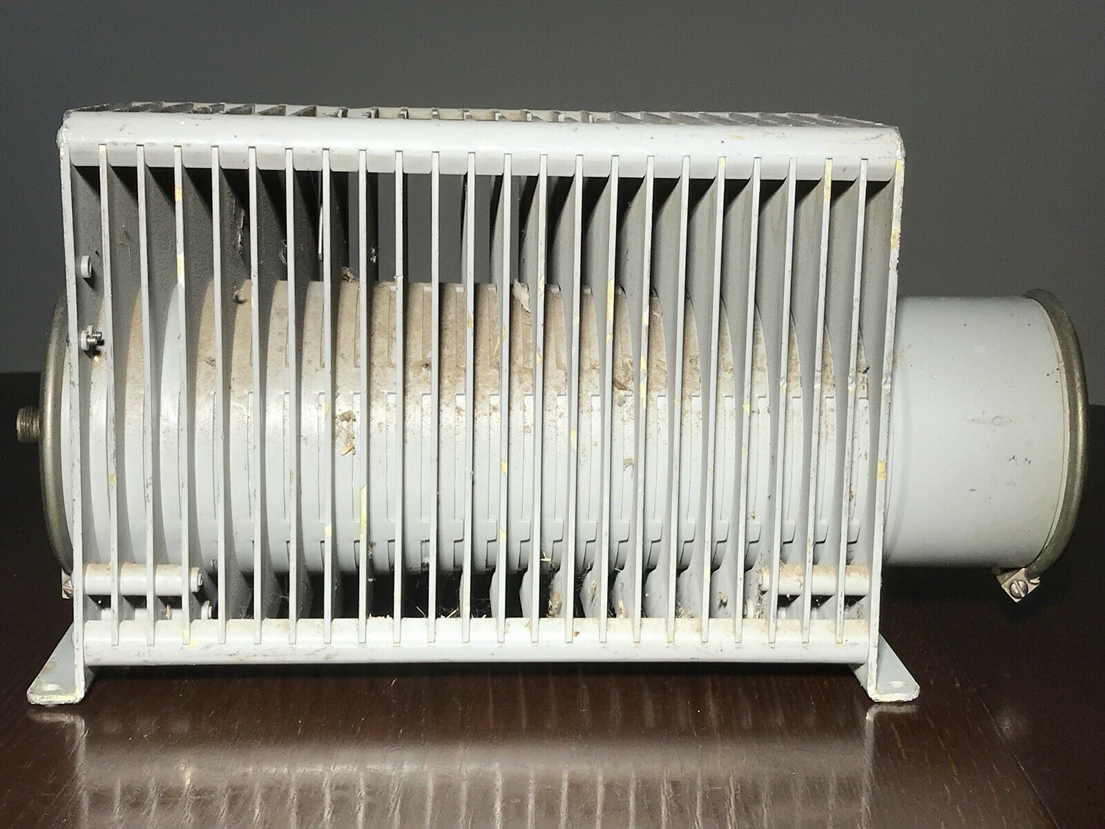
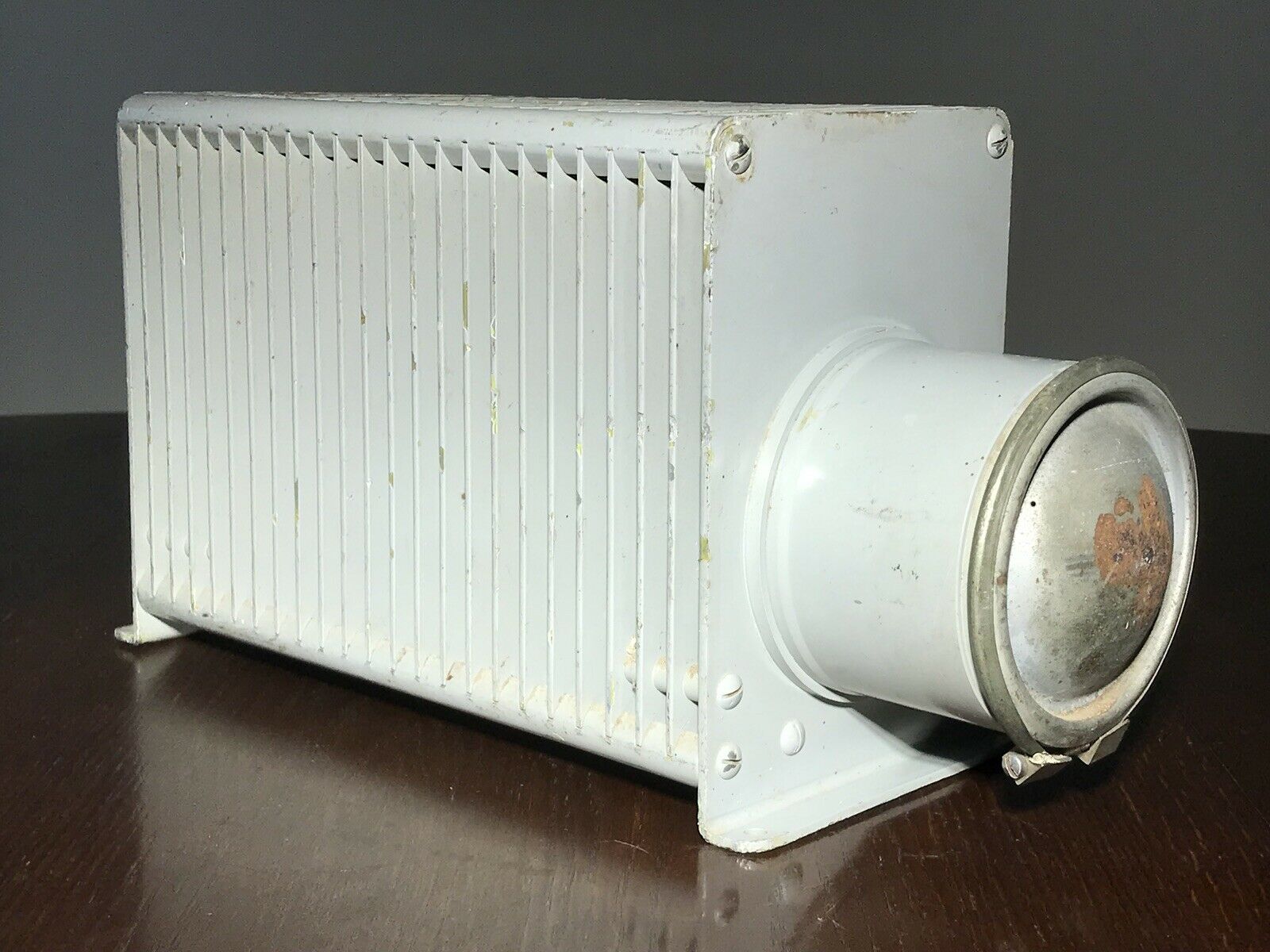
DA-274/U Dummy Load
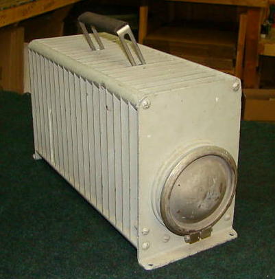
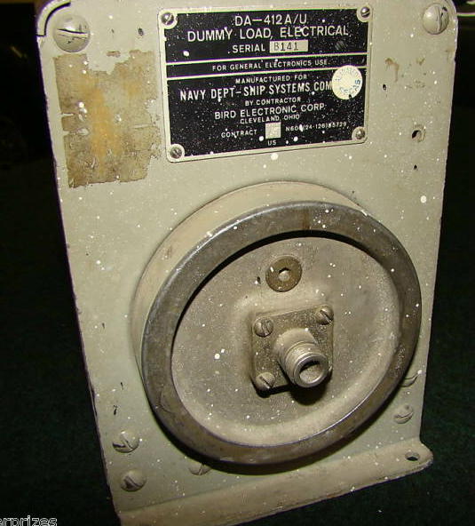
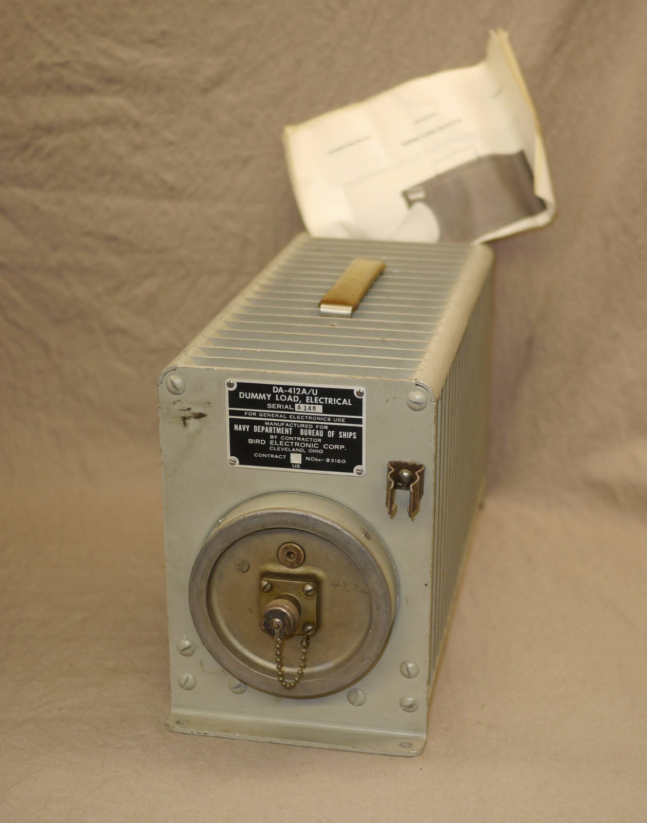
DA-412A/U Dummy Load
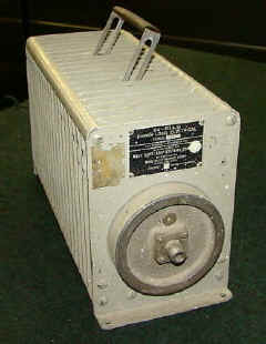
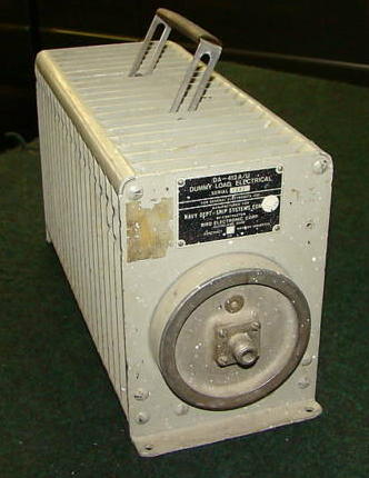

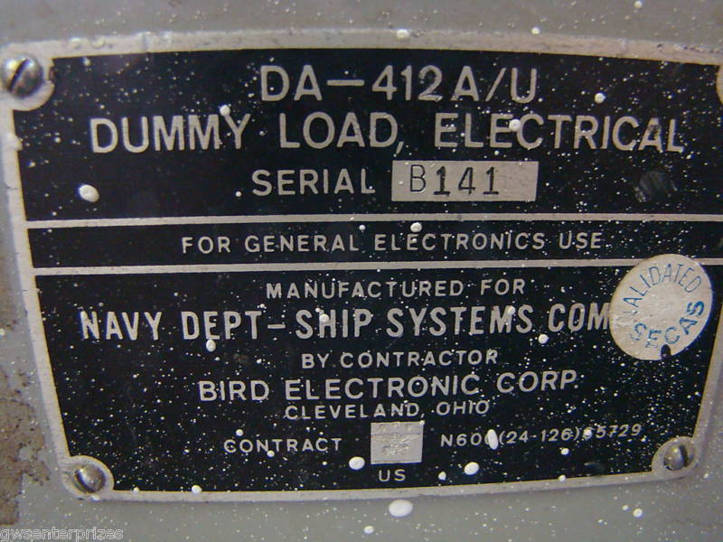
Instructions

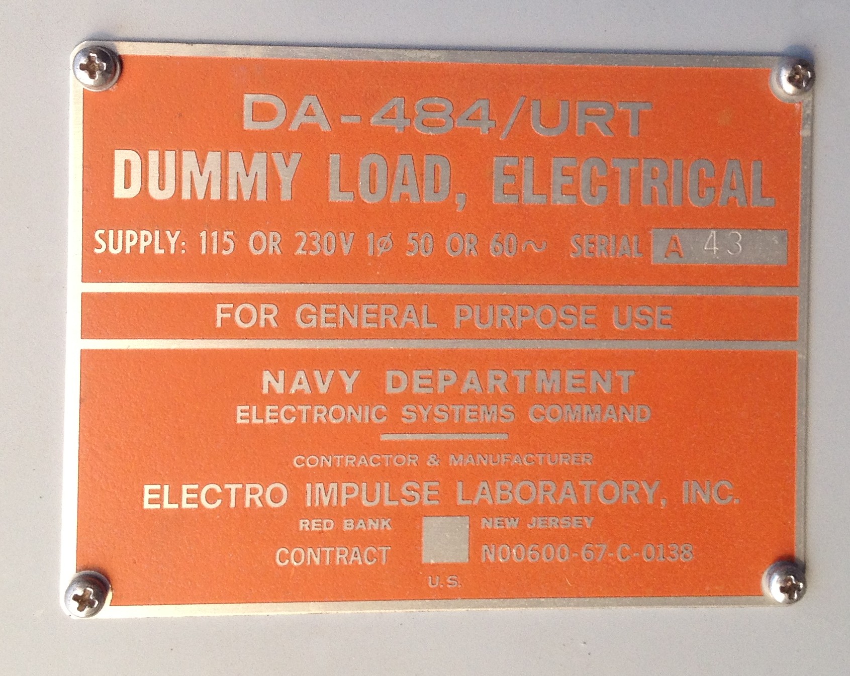
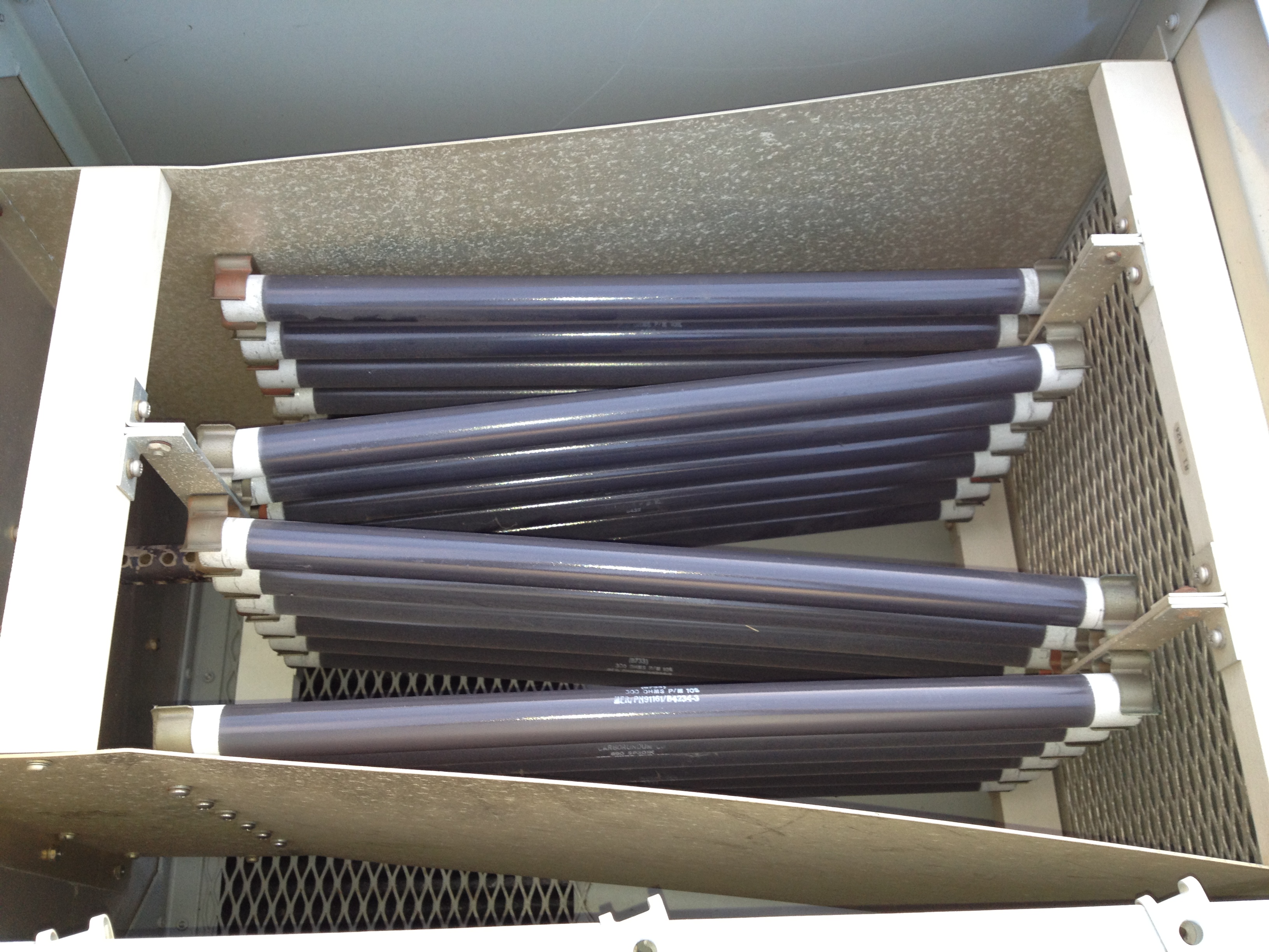
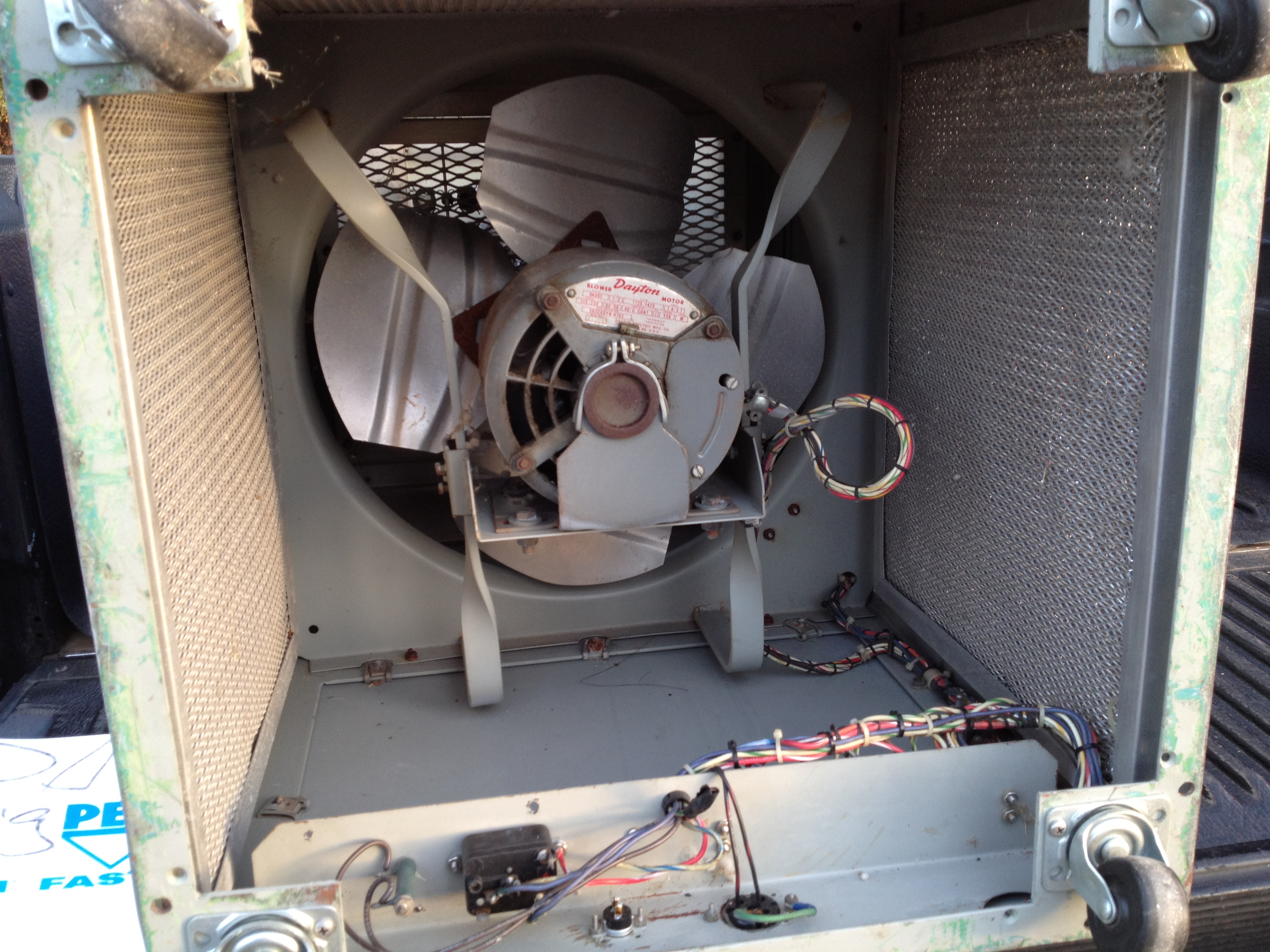
DA-484/URT Dummy Load
10kw air-cooled 2-30 mc - 5' tall cabinet with a large fan in the bottom and 24 ea. 300 ohm resistors in the top portion.
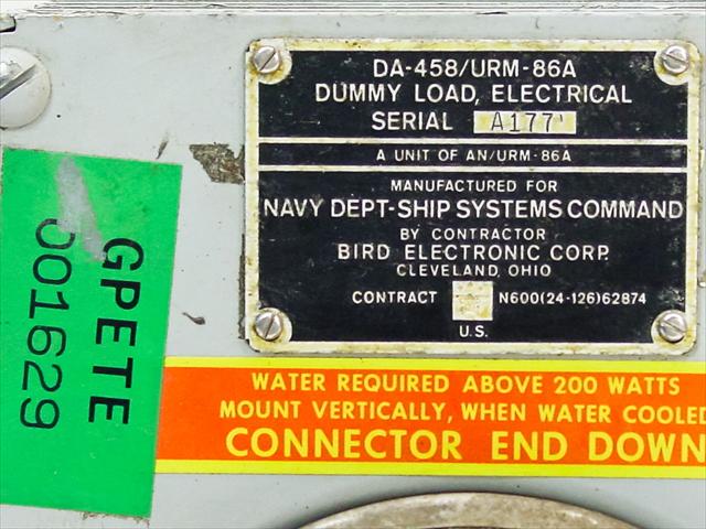
DA-458/URM-86A Dummy Load

used with IM-??/URM-86A meter?
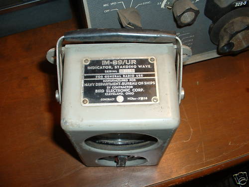
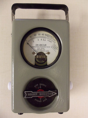
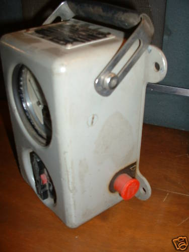
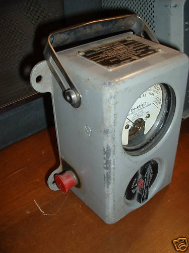
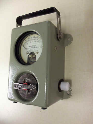
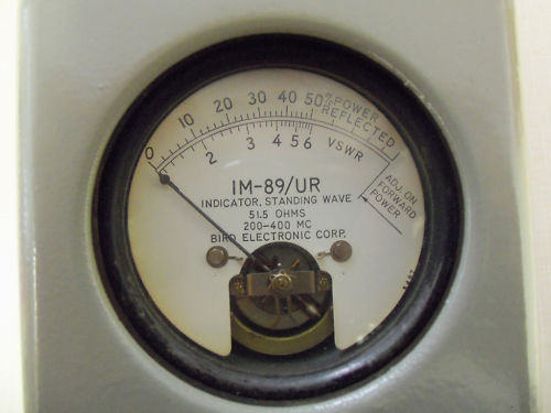
IM-89/UR SWR Meter
200-400 Mc
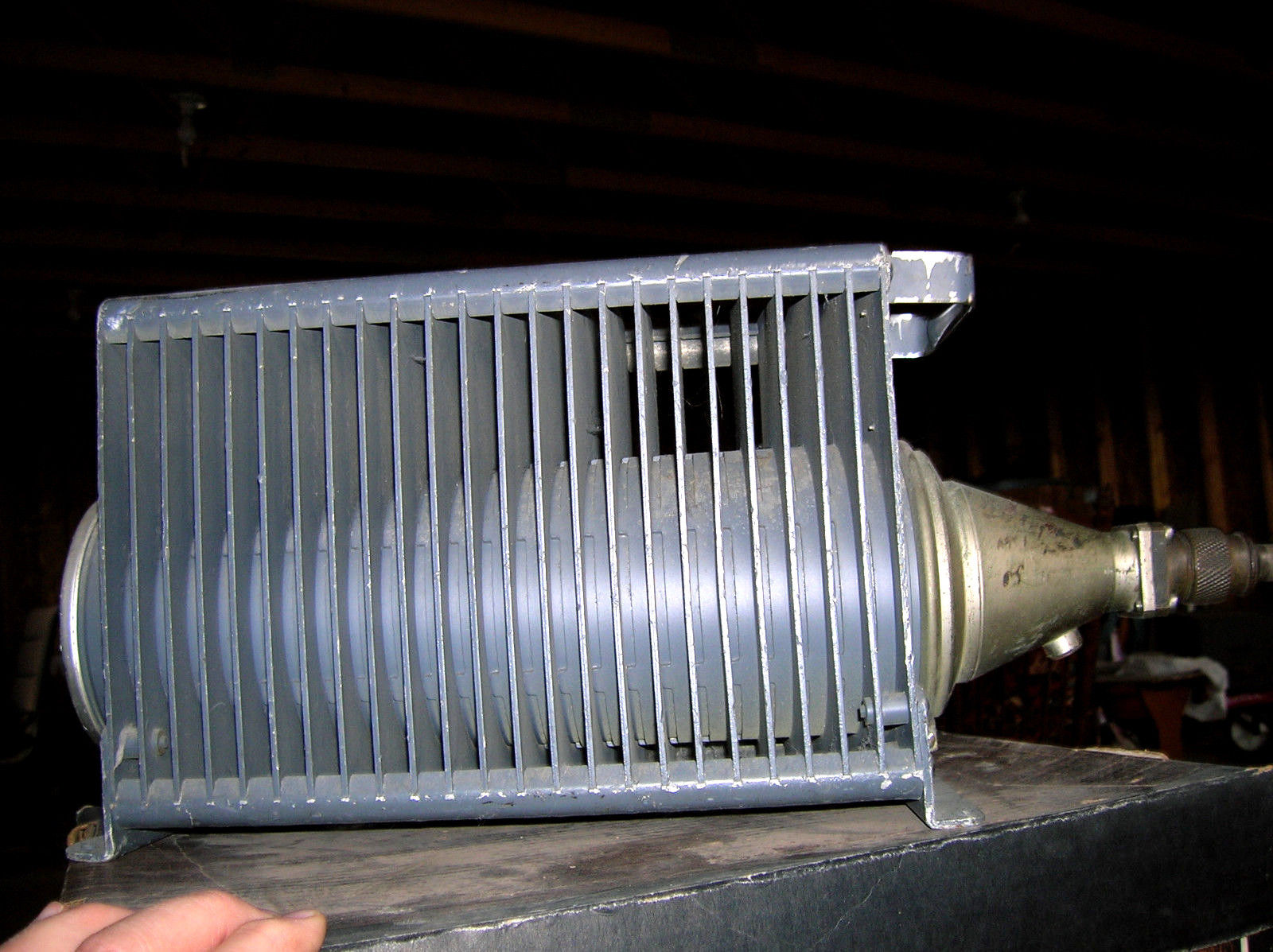
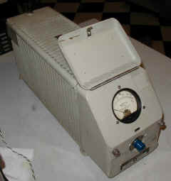
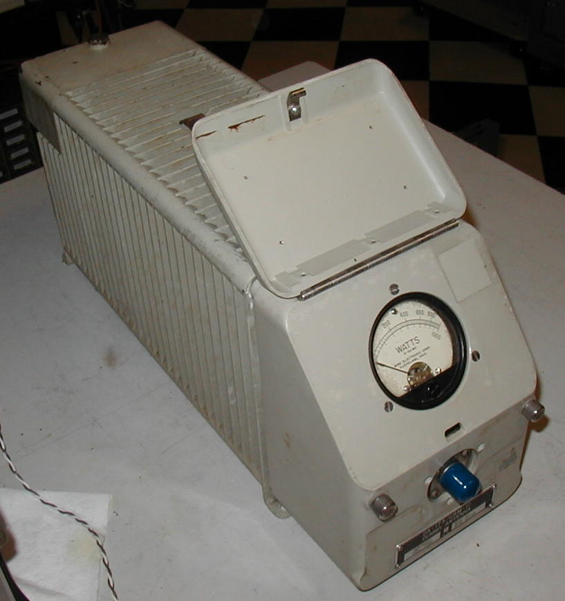
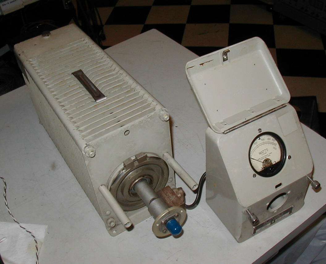
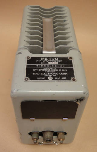
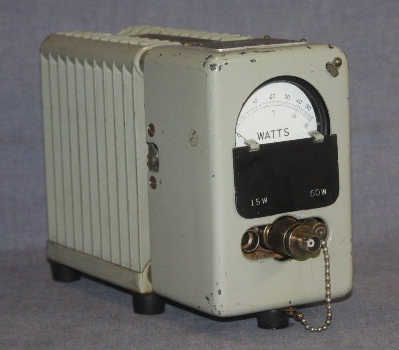
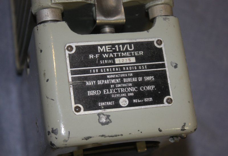
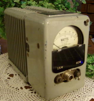
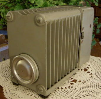
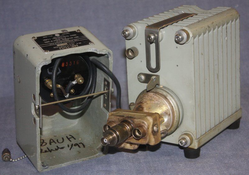
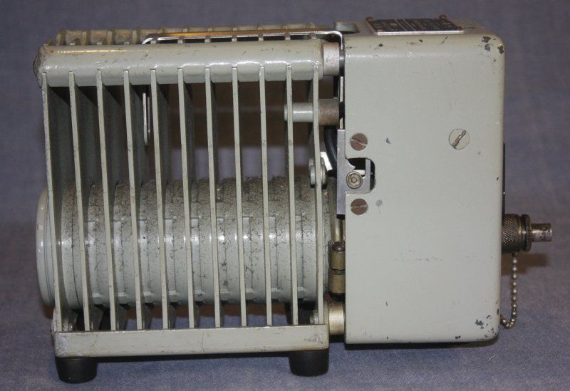
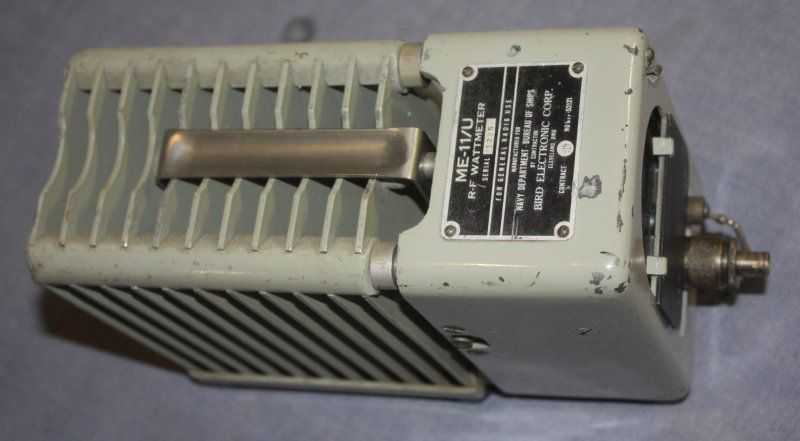
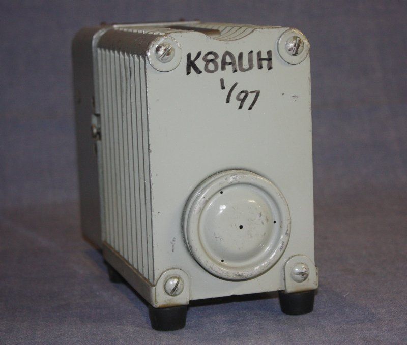
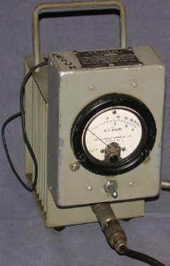
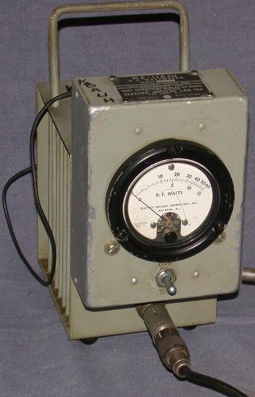
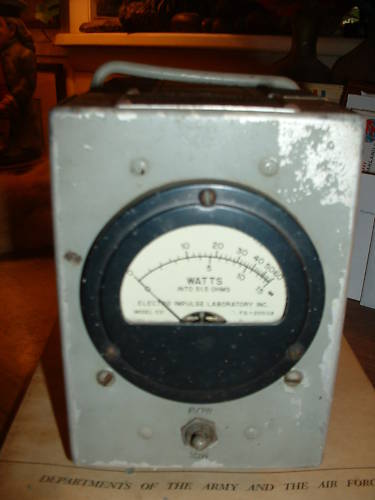
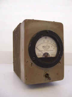
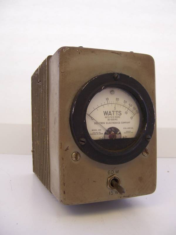
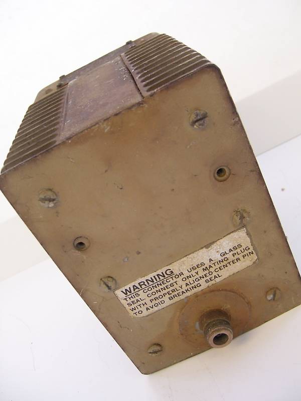
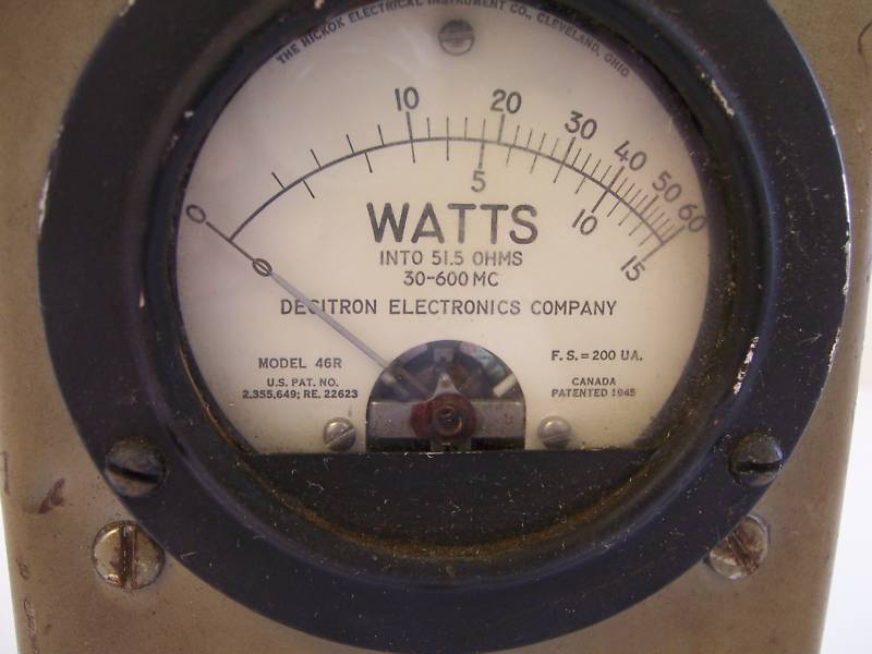
ME-11/U wattmeter & dummy load (15 w and 60 w scales)
(30-500 mc)
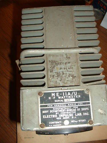
ME-11A/U
(30-600 mc)
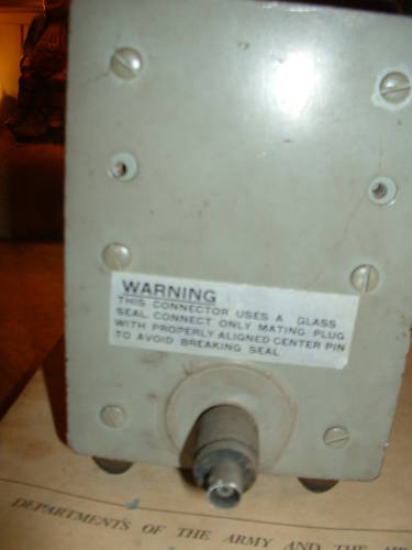
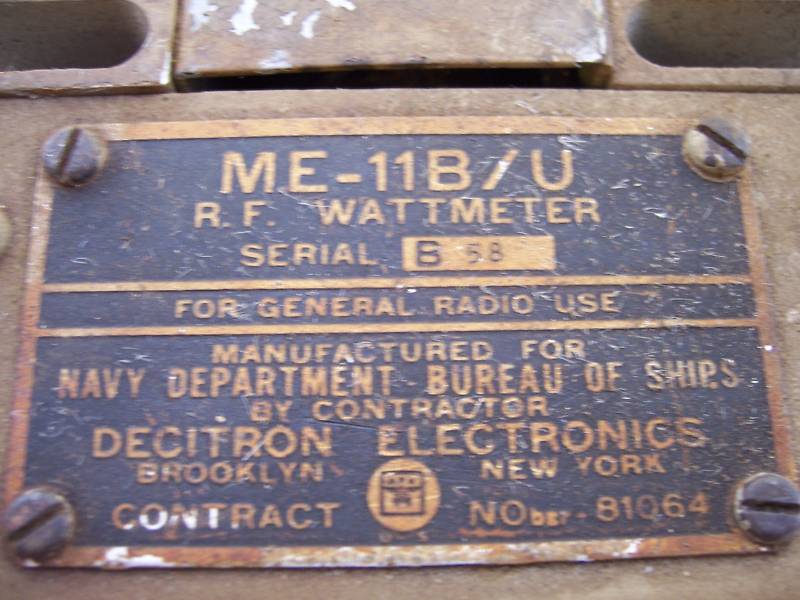
ME-11B/U
(30-600 mc)
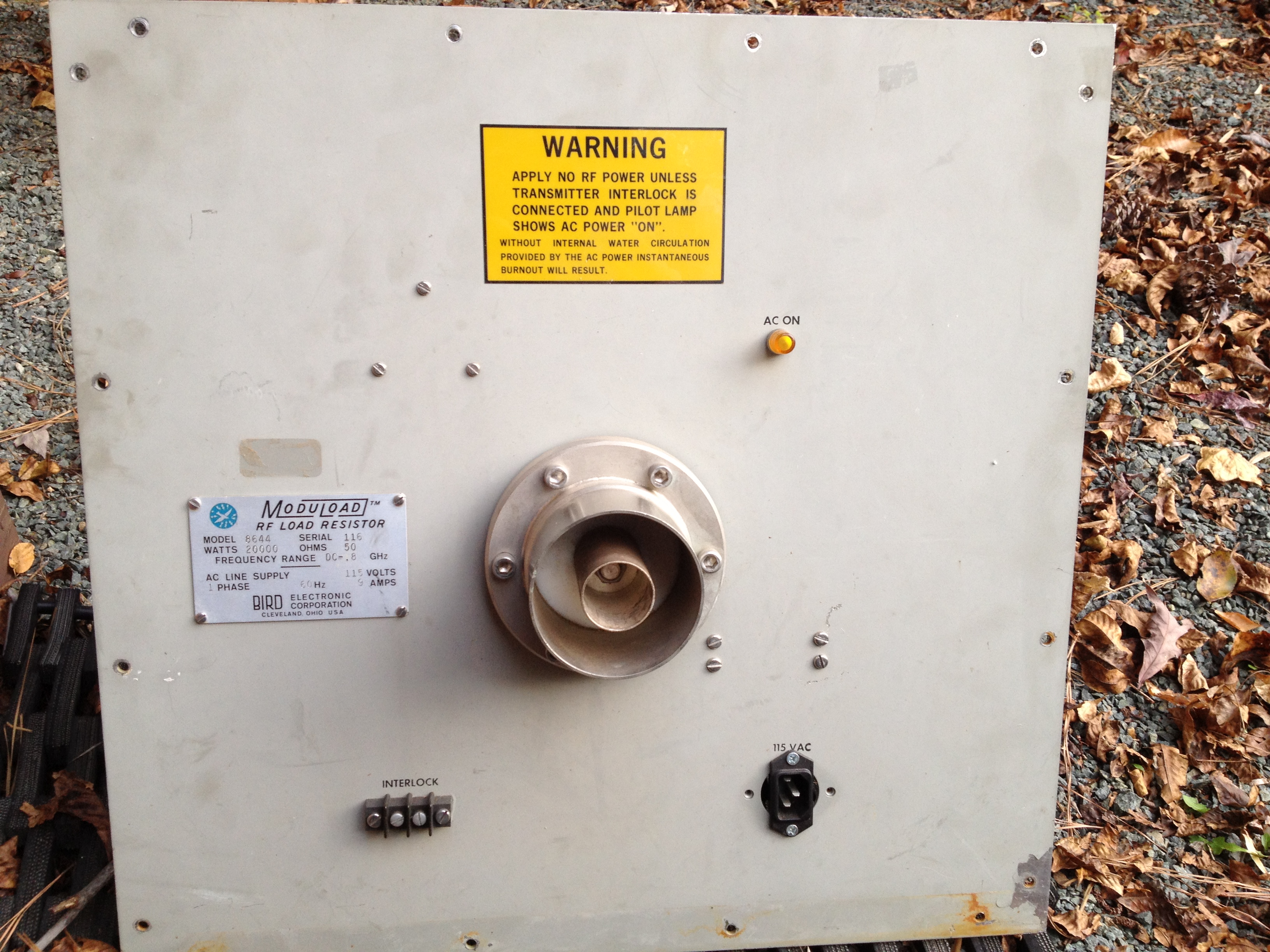
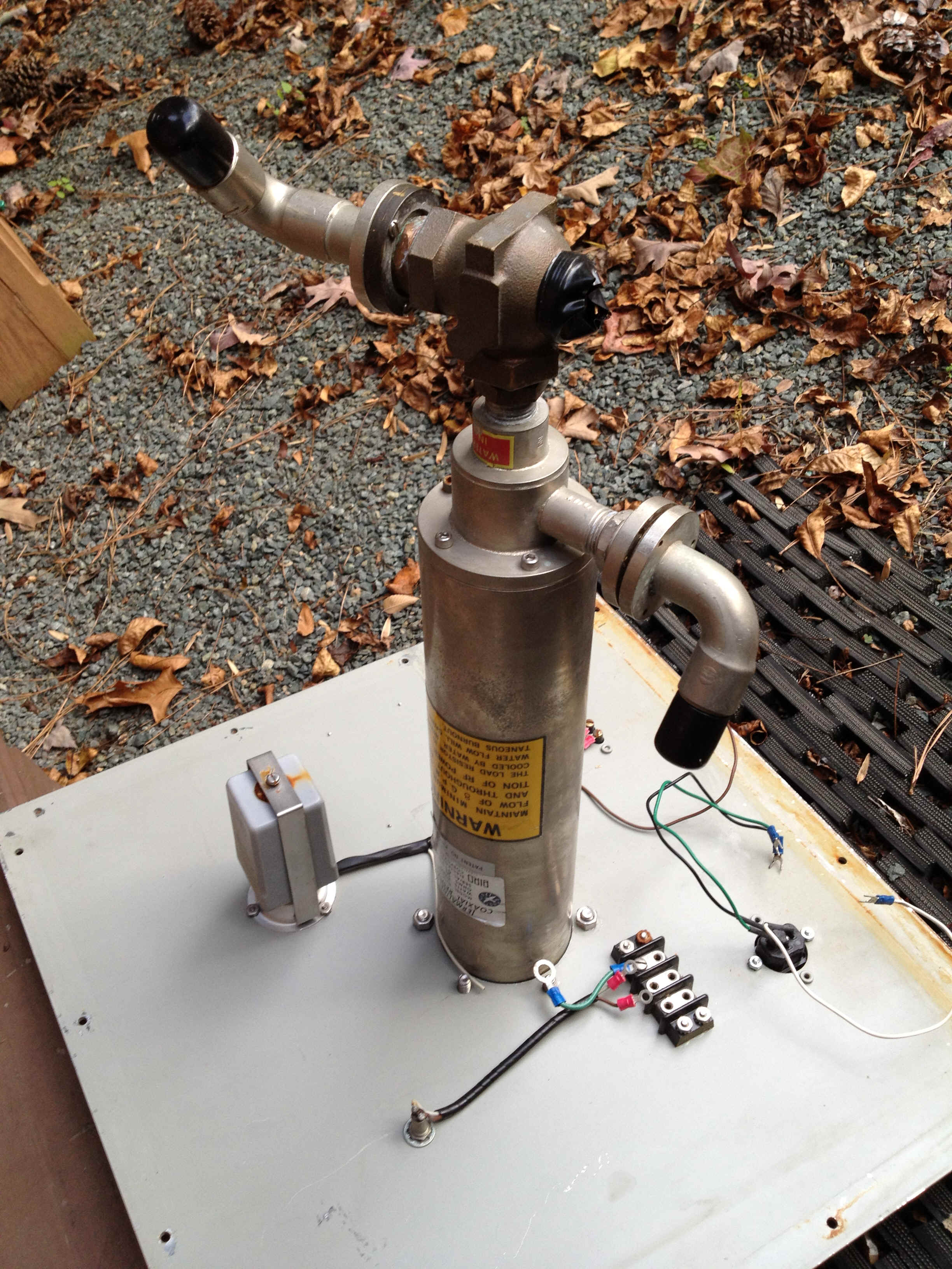
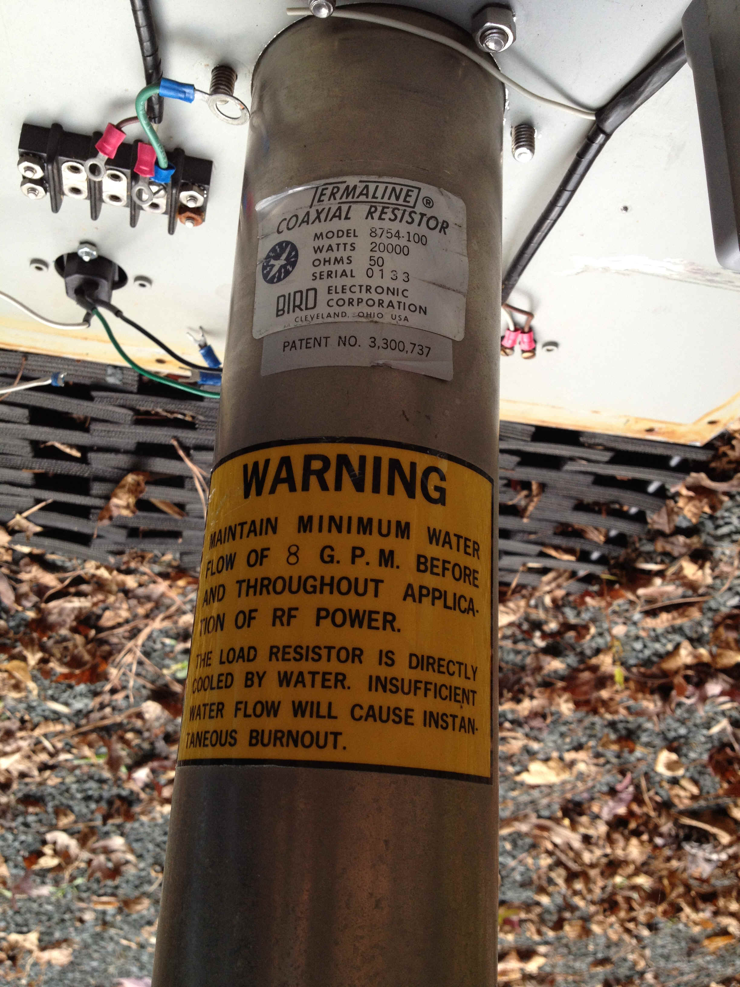
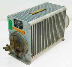
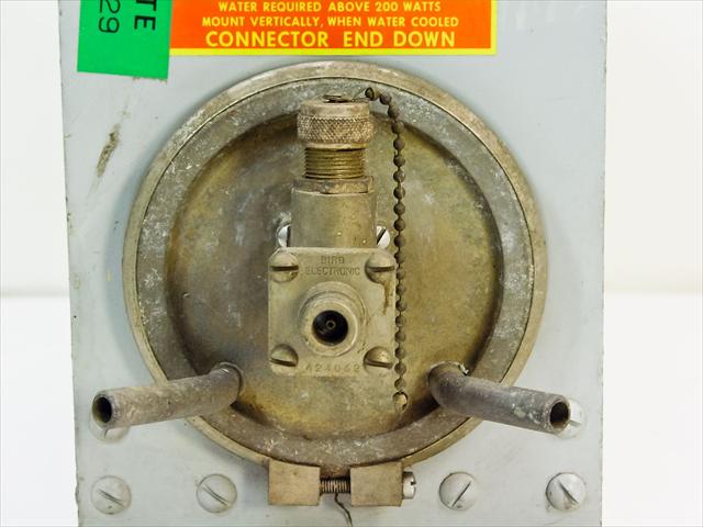
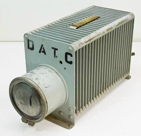
Bird 8644 20kw dummy load
water-cooled DC-800mc
8gpm minimum