1956 CLC-1 Cruise Book Photos - Thanks to Doug at www.greatnavalimages.com
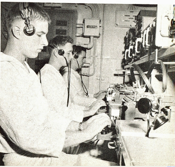
Radio Central - AN/SRR-13 receivers
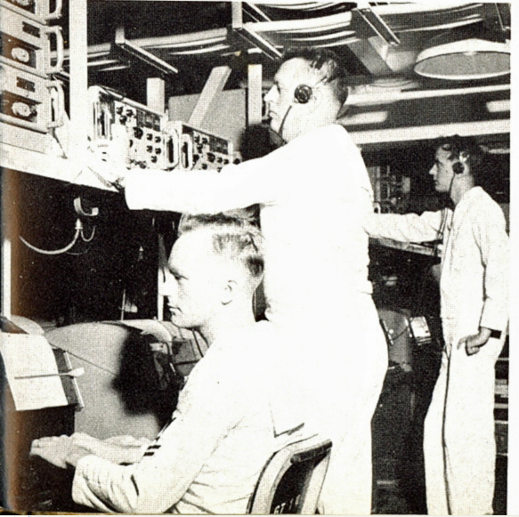
Teletype Room - AN/SRR-13 receivers
AN/URA-8A converters
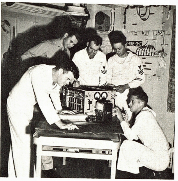
Transmitter Room - AN/URT-3 RF Amp
1956 CLC-1 Cruise Book Photos - Thanks to Doug at www.greatnavalimages.com |
||
Radio Central - AN/SRR-13 receivers |
Teletype Room - AN/SRR-13 receivers AN/URA-8A converters |
Transmitter Room - AN/URT-3 RF Amp |
Figures 3 -31 through 3-37 illustrate portions of the radio communications system installed on the new Task Fleet Command Ship, USS Northampton (CLC-1). A vessel of this type and size requires a large number of communication circuits. Normally, a correspondingly large number of antennas would be required for these circuits. However, by using antenna multicouplers; the number of antennas required has been greatly reduced.
The multicoupling system on the CLC-1 employs approximately 58 multicouplers and 25 antennas. The receiving antennas are located forward and the transmitting antennas aft to provide maximum isolation between the two types. Note the use of broad-band sleeve type antennas.
| a. RADIO TRANSMITTING SYSTEM.-The transmitter multicoupling system for the CLC-1 is illustrated in Figures 3 -31 and 3 - 32. Eight multicouplers are used in this system: three transmitting Filter Assemblies and five HF Multicouplers. Six antennas are used with these multicouplers: five sleeve antennas and one flat -top antenna. | |
Transmitting Room No. 1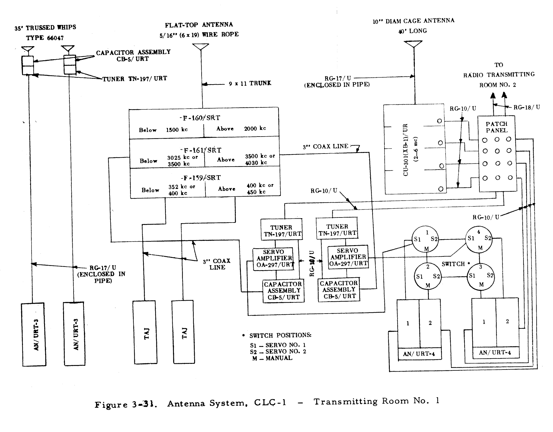 |
Transmitting Room No. 2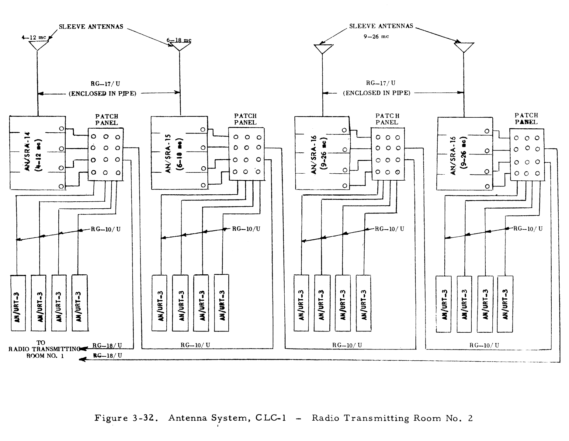 |
| b. RADIO RECEIVING SYSTEM. - The receiver multicoupling system is shown in Figures 3- 33 and 3- 34. This system uses six AN/SRA-9 Receiving Filter Assemblies. Six antennas are used with these multicouplers: five sleeve antennas and one wire receiving antenna. | |
Radio Central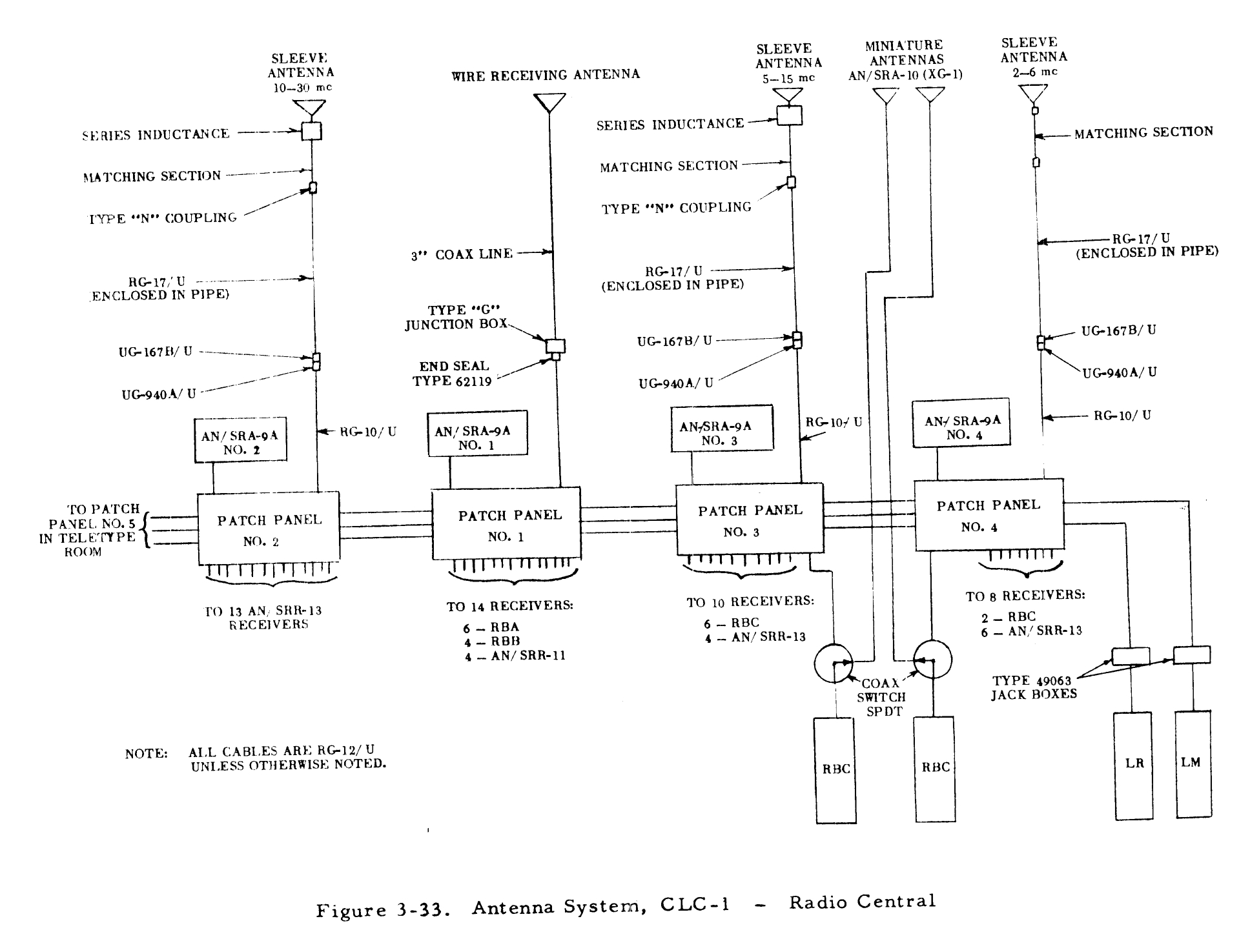 |
Teletype Room |
| e. UHF SYSTEM. - The UHF multicoupling system for the CLC-1 is shown in Figures 3-35 through 3-37. Forty-four UHF Multicoupler are used: twelve CU-255/UR Antenna Couplers and thirty-two CU-332/UR Antenna Couplers. The system employs eleven UHF antennas: three AT-150/SRC dipoles and wight AS-390/SRC stub antennas. | |
UHF Room No. 1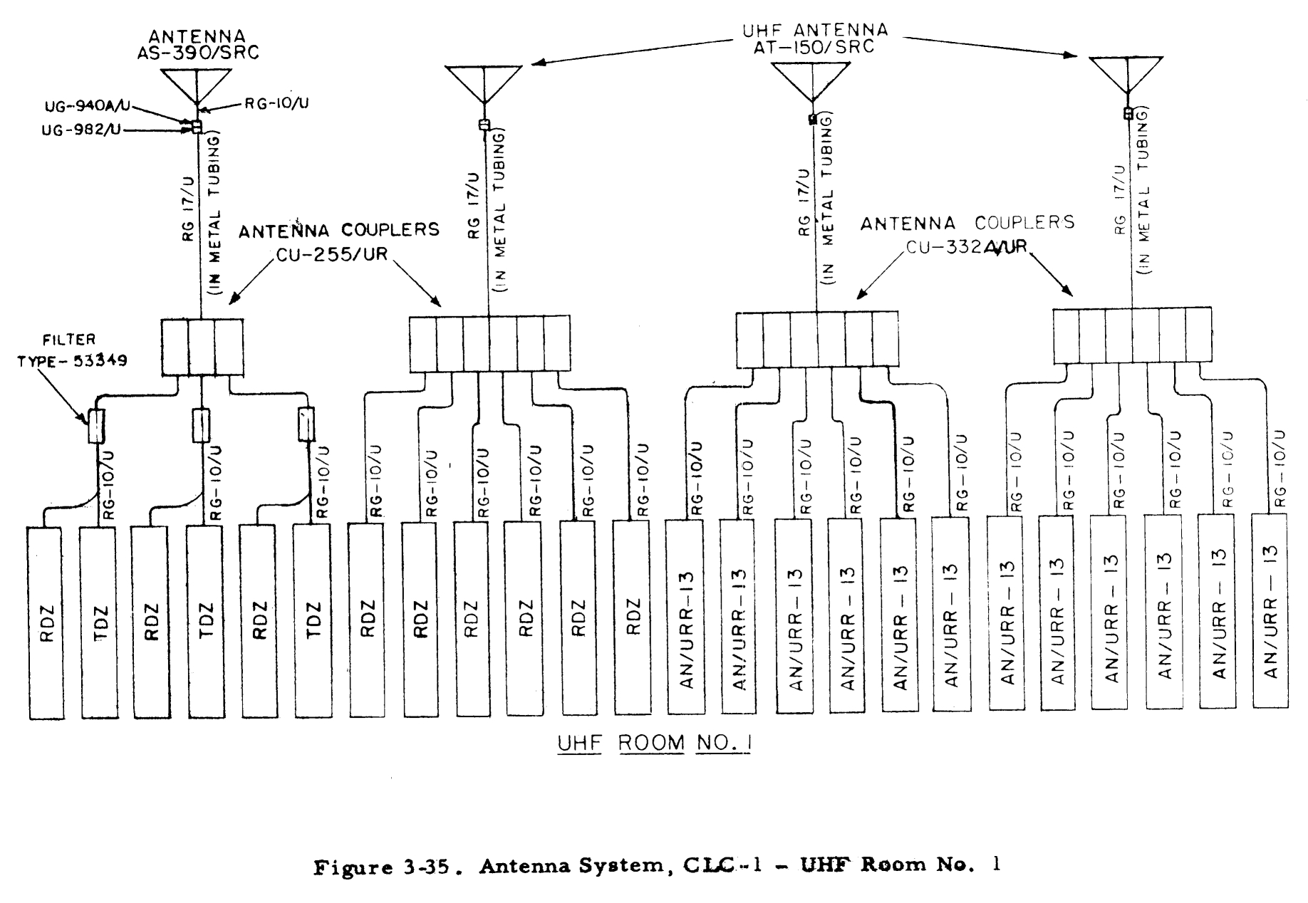 |
UHF Room No. 2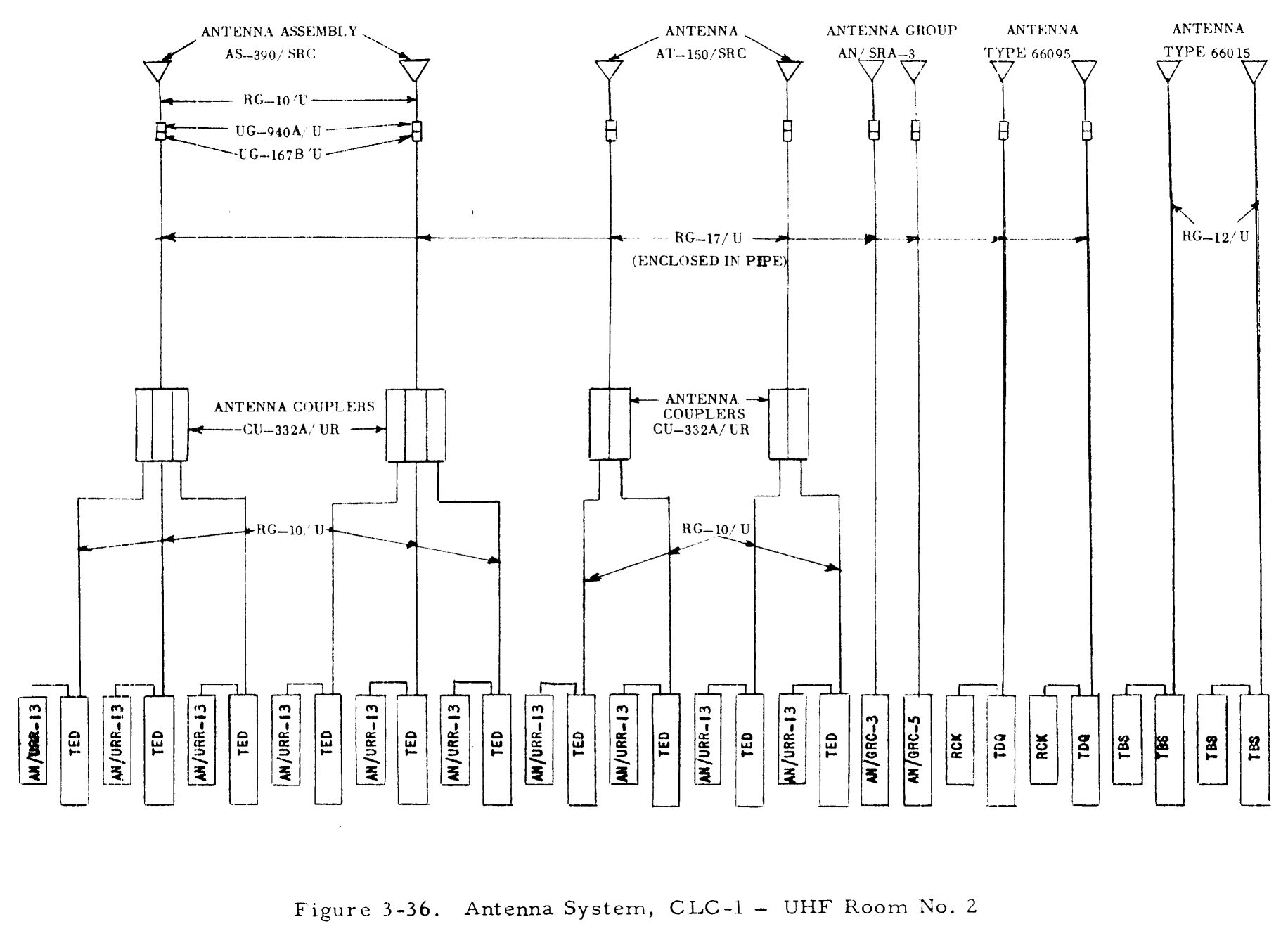 |
UHF Room No. 3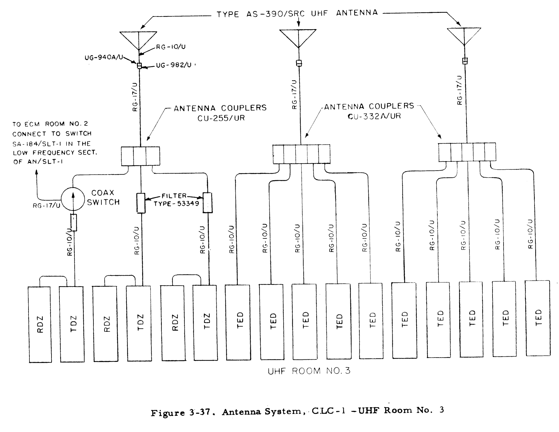 |
-- |
Sleeve antennas, flat-top antenna mast, and aft discone visible (date unknown)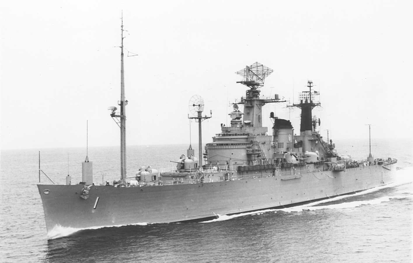 |
1964 photo from aft - 35' whips and wire antennas are visible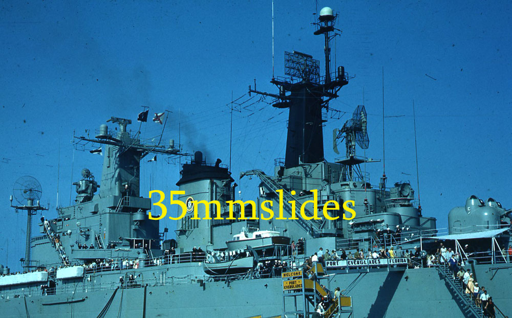 |