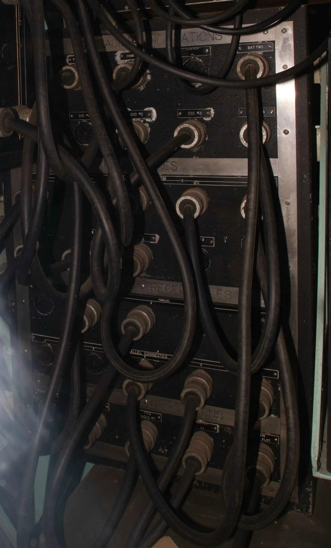
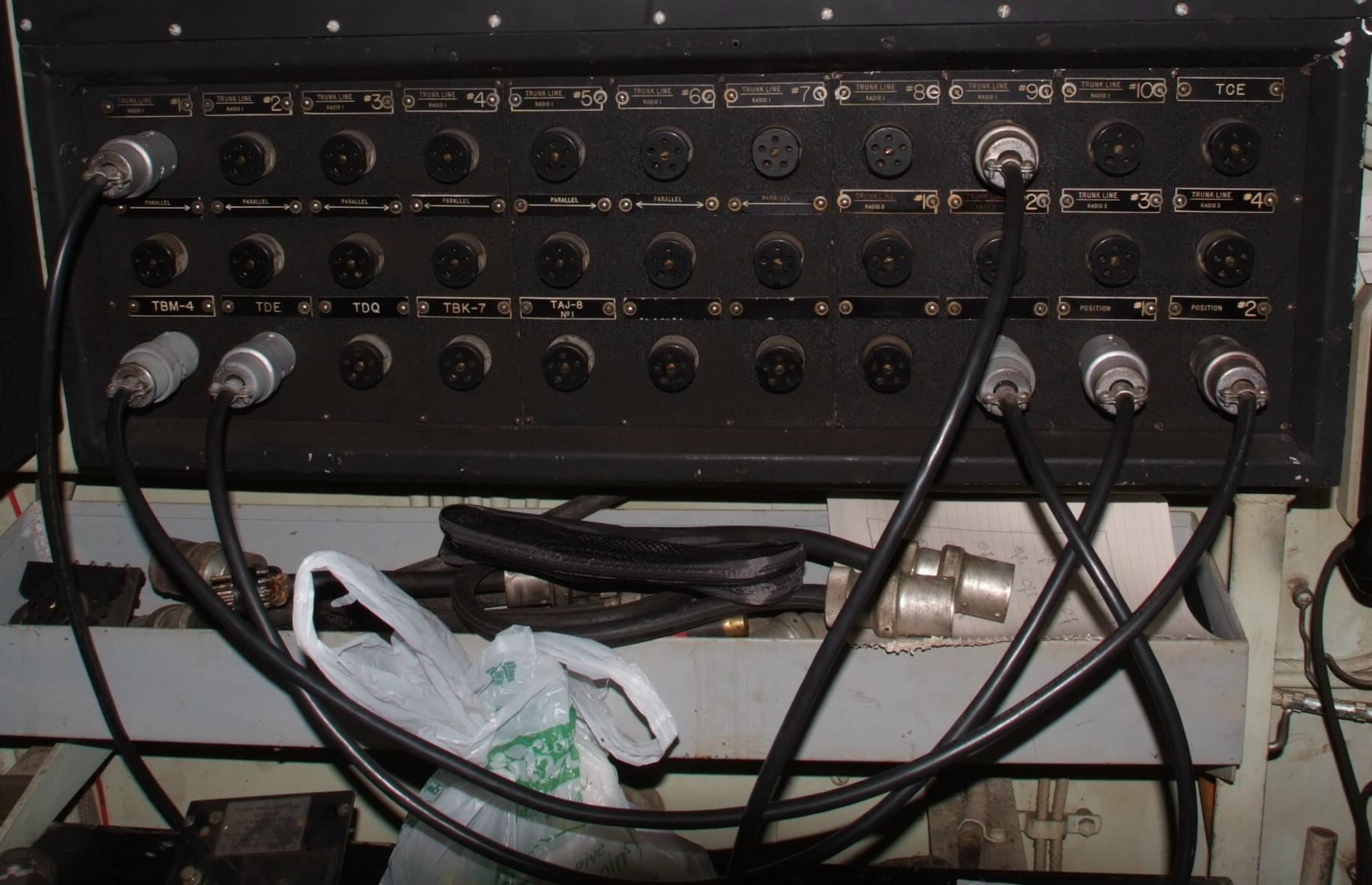
RadioPhone Patch Panels
Radio 1 (Radio Central)
RadioPhone Patch Panels
Radio 2 (Transmitter Room)
Key / Control Patch Panels
Radio 1 (Radio Central)
Key / Control Patch Panels
Radio 2 (Transmitter Room)
RadioPhone Patch Panel (11-wire)
Type RN-23206
RadioPhone Patch Panel (11-wire)
Type RN-23208
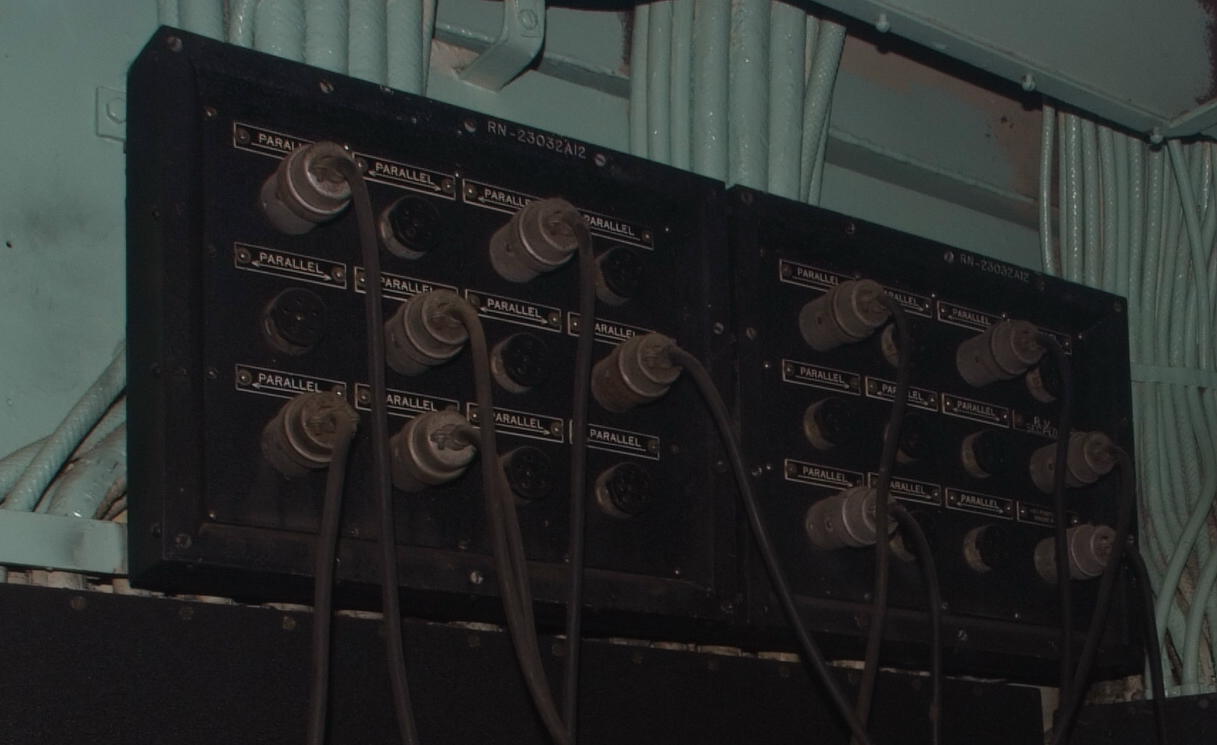
Parallel Jacks (6 rows, 4 jacks/row)
2 ea. Type RN-23032A12
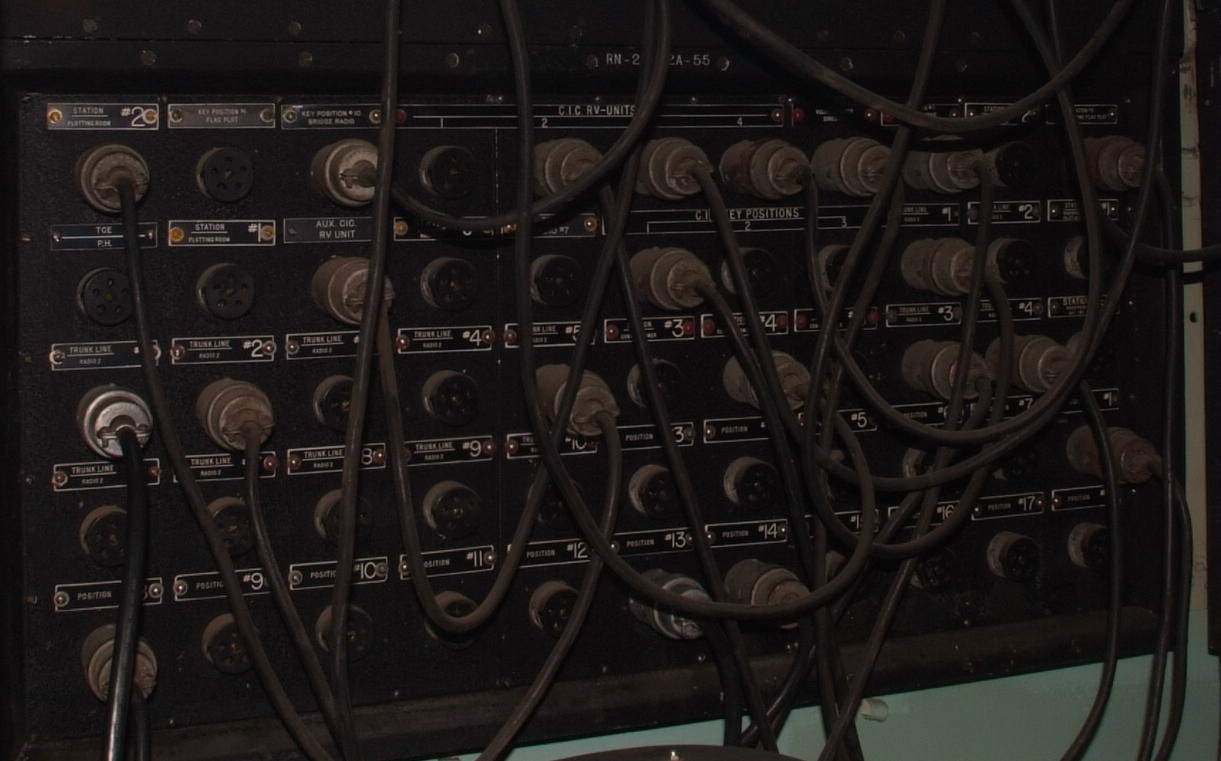
Key Control Patch Panel (5-wire)
Type RN-2302A-55
Key Control Patch Panel (5-wire)
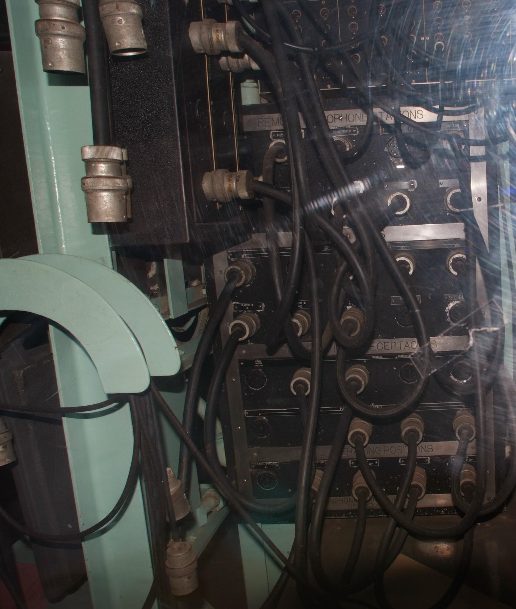
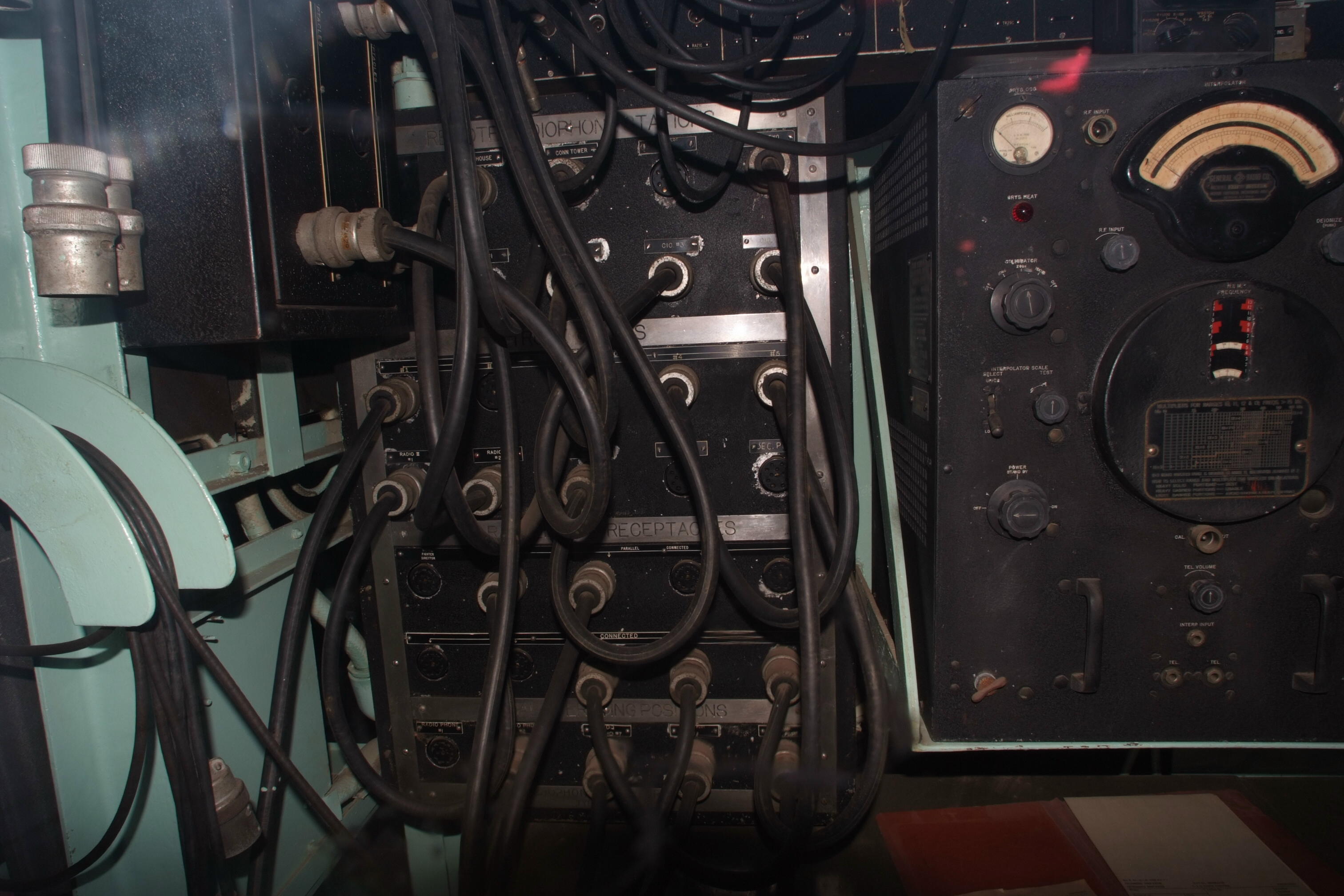
- Remote Radiophone Stations
- Pilot House
- Conn Tower
- Flag Plot #1
- Bat Two (Battle Two)
- CIC (1-4)
- Trunk Lines
- Radio 2 Trunk Lines (1-5)
- Radio 3 Trunk Lines (1-2)
- Aux CIC
- Radio 3 Trunk Line 3
- Sec Plot
- Parallel Receptacles
- Visual Fighter Director
- Parallel Lines 2-5
- Parallel Lines 6-10
- Local Operating Positions
- Radiophone #1, #2
- TDQ Radio 7
- Flag Plot #2
- Main Batt Plot
- Trunk Lines
- Radio 1 Trunk Lines (1-5)
- Radio 3 Trunk Lines (1-3)
- Local Transmitters
- TBM
- TBK-7
- TDE
- TDQ
- Local Operating Positions
- Positions 1-4
- Row 1
- Plotting Room 2
- Flag Plot Key Pos. 1
- Bridge Radio Key Pos. 10
- CIC RV Units 1-4
- Visual Fighter Director
- Flag Plot Radiophone 1
- Conning Tower Radiophone 2
- Flag Plot Radiophone 2
- Row 2
- TCE - P.H.(Pilot House?)
- Plotting Room 1
- Aux. CIC RV Unit
- Flag Plot Radiophone 3
- TDQ Radio 7
- CIC Key Positions 1-3
- Radio 3 Trunk Line 1-2
- Conning Tower Radiophone 1?
- Row 3
- Radio 2 Trunk Line 1-5
- Conning Tower 3-5
- Radio 3 Trunk Line 3-4
- ? Station 5
- Row 4
- Radio 2 Trunk Line 6-10
- Position 3-7
- Position 1
- Row 5
- Position 8-17
- Position 2
- Radio 1 Trunk Lines (1-10)
- Radio 3 Trunk Lines (1-4)
- Transmitters - TCE, TBM-4, TDE, TDQ, TBK-7, TAJ-8
- Local Operating Positions (1-2)
- Parallel Jacks (4 + 3)
- Blank / No Longer Used (4)
RadioPhone Patch Panel (11-wire)
RadioPhone Patch Panel (11-wire)
Radiophone connector
- +/- 12v dc
- microphone
- Carrier Control (PTT)
- Carrier Control Indicator
- Receiver Mute
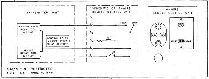
4-wire key/control system diagram
note - 5-pin plug, but 4-wire system
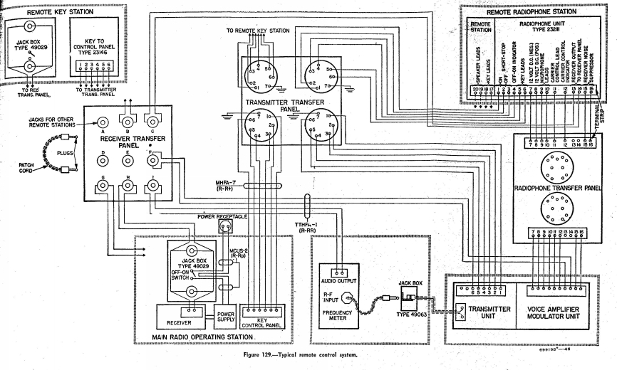
Radiophone and key/control system diagram - this shows later 6-wire
key/control but otherwise applicable to BB-55