"Radio Teletype Systems Afloat - Carrier Frequency Shift Receiving
System" - BuShips Journal June 1958
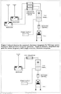
Figure 1 (above) depicts the essential electronic equipment for Teletype carrier
frequency shift diversity reception operation. Figure 2 (below): Simplified diagram for carrier frequency shift single receiver, converter reception. |
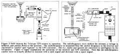
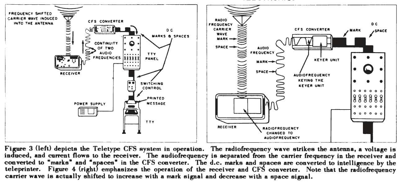
Figure 3 (left) depicts the Teletype CFS system in operation. The
radio frequency wave strikes the antenna, a voltage is induced, and current flows to the receiver. The
audio frequency is separated from the carrier frequency in the receiver and
converted to "marks* and "spaces" in the CFS converter. The d.c. marks and spaces are converted to intelligence by the
teleprinter. Figure 4 (right) emphasizes the operation of the receiver and CFS converter. Note that the
radio frequency carrier wave is actually shifted to increase with a mark signal and decrease with a space signal. |
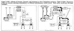
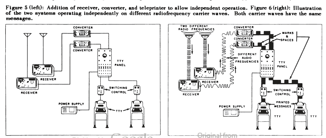
Figure 5 (left): Addition of receiver, converter, and teleprinter to allow independent operation. Figure
6 (right): Illustration of the two systems operating independently on different
radio frequency carrier waves. Both carrier waves have the same messages. |
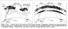
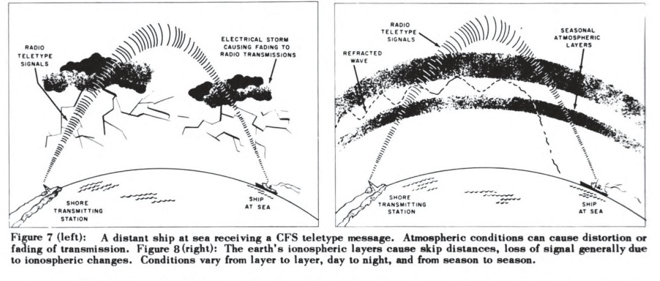
Figure 7 (left): A distant ship at sea receiving a CFS teletype message. Atmospheric conditions can cause distortion or
fading of transmission. Figure 8 (right): The earth's ionospheric layers cause skip distances, loss of signal generally due
to ionospheric changes. Conditions vary from layer to layer, day to night, and from season to season. |
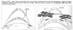
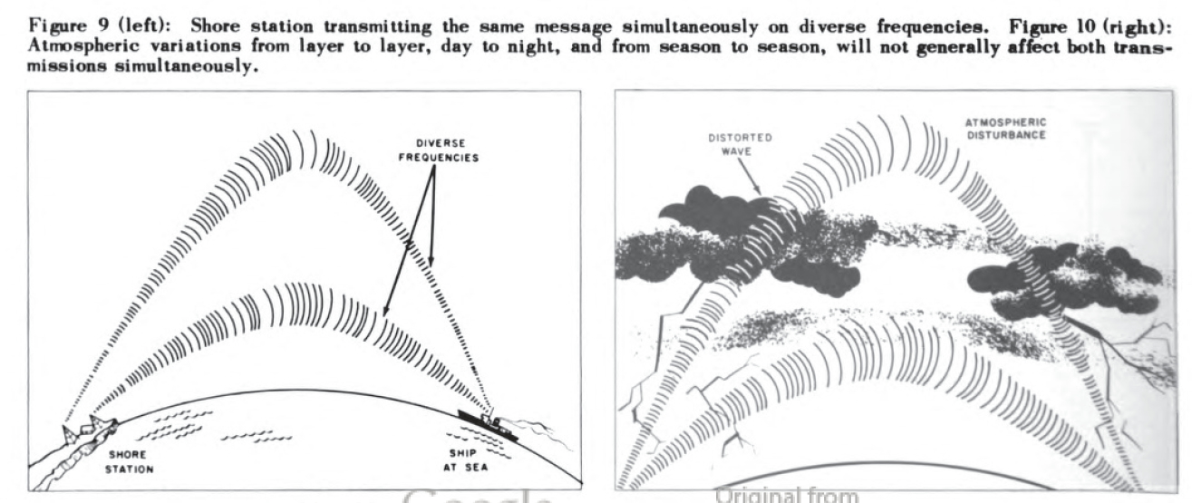
Figure 9 (left): Shore station transmitting the same message simultaneously on diverse frequencies. Figure 10 (right):
Atmospheric variations from layer to layer, day to night, and from season to season, will not generally affect both
transmissions simultaneously. |
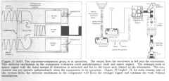
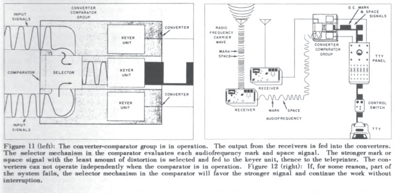
Figure 11 (left): The converter-comparator group is in operation. The output from the receivers is fed into the converters.
The selector mechanism in the comparator evaluates each audio frequency mark and space signal. The stronger mark or
space signal with the least amount of distortion is selected and fed to the
keyer unit, thence to the teleprinter. The converters can not operate independently when the comparator is in operation. Figure 12 (right): If, for some reason, part of
the system fails, the selector mechanism in the comparator will favor the stronger
signal and continue the work without interruption. |
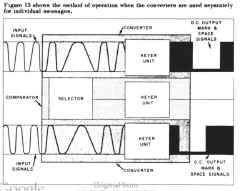
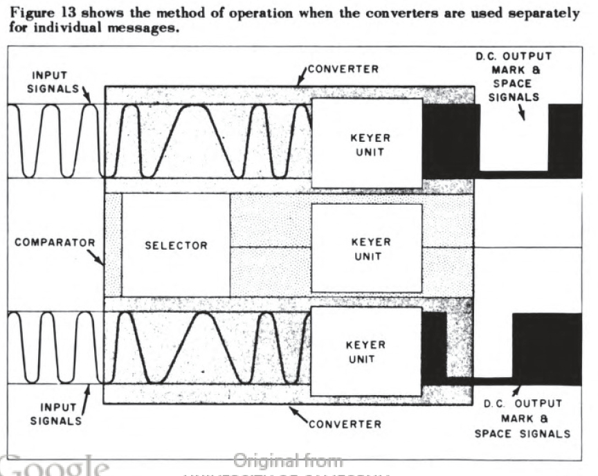
Figure 13 shows the method of operation when the converters are used separately
for individual messages. |
"Radio Teletype Systems Afloat - Carrier Frequency Shift Receiving System"
By Joseph J. Fisher, Communications Section, Bureau of Ships
In the Navy's radio teletype systems afloat, the carrier frequency shift system is generally
used for long range communications. Three preceding articles in the Journals of April, September,
and December 1956 explained how the signals in the Navy's radio teletype systems were formed for
short range operations and for the carrier frequency shift transmit system. This article describes
the basic operation of the carrier frequency shift receiving system.
A standard shipboard installation has two radio receivers, a receiver transfer switchboard, a
converter-comparator group, a teletype panel, a switching control, a teleprinter, and a power supply
(figure 1).
For simplicity of explanation figure 2 depicts a simplified system with one receiver, one of the
converters, and the comparator removed from the full system shown in figure 1. Assuming the
switching control is set for "carrier frequency shift receive," and the power supply is furnishing the
necessary looping current to the teletype panel, the signal may be followed.
The signal in its path from the antenna to the teleprinter takes various forms, that is, the same
message is in three types of signals: From the antenna into the receiver, it is a frequency-shifted radio
carrier wave (figure 3); from the receiver to the converter, it is a continuity of two
audio frequencies; and from the converter through the teletype panel and switching
control to the teleprinter it is direct current (d.c.) "marks" and "spaces."
The signal changes take place in the receiver and converter. The receiver is used to tune in the
radiofrequency carrier wave with its mark and space frequency shifts. Also the receiver separates the
audio frequency from the carrier wave (figure 4).
The receiver output of mark and space audio frequencies is then fed into the converter (figure 4), where
they operate a keyer unit that converts them into their corresponding d.c. marks and spaces. These
mark and space signals operate a selector magnet in the teleprinter machine that changes the electrical
impulses into printed characters to form intelligence in a message format.
To illustrate further, return to figure 2 the receiver and converter previously removed and add a
switching control, and a standby teleprinter as shown in figure 5.
Then, assume that the second receiver is receiving a different incoming message on a different
carrier shift radiofrequency that is channeled through a separate loop in the teletype panel (figure 6).
With this arrangement, two separate messages can be received simultaneously on two teleprinters.
However, if the second teleprinter is eliminated and the comparator replaced so that the
converters and comparator are a unit once again, then a third method of operation is possible (figure 1).
Fading
As previously stated, this system was designed for long range radio teletype operations. The
carrier frequency shift system is the best way to send the teleprinter's rapidly keyed signals
over long distances where fading and interference are generally present.
If the atmospheric conditions are good, the frequency shifted carrier wave will deliver a strong
signal to a receiver far away. Reception will vary as determined by atmospheric conditions which
may weaken and garble the signal or may cause it to fade out entirely from time to time (figures 7 and 8).
Also conditions may vary at times from one atmospheric layer to another, or from day to night,
and from season to season. Such variations may also distort and weaken the signal, even cause it
to disappear momentarily.
Such conditions and variations should not affect two different frequencies in the same way at the
same time. At any given moment they may garble or weaken one signal but not the other. Two
different frequencies will seldom be faded or distorted simultaneously. Therefore for reliable long-range
radio teletype operations, the Navy uses frequency diversity transmission.
In frequency diversity operation, the same message is sent simultaneously on separate carriers of
two different (diverse) frequencies. One or the other should get the message through regardless of
weather conditions, interference, and atmospheric variations (figures 9 and 10).
To operate with frequency diversity requires two receivers and two converters. The converters are combined with a comparator to form the converter comparator
group. When in operation the comparator selects the stronger of the two diverse signals, and sends
it to the teleprinter.
Figure 1 shows the converter comparator group connections terminating into three separate loops
in the teletype panel. For frequency diversity reception, the receivers are tuned, to receive the
same message, on two different radiofrequencies that may continually vary in strength because
of atmospheric conditions. The strengths of the audio outputs of the two receivers will vary
accordingly.
In the converter-comparator group a simple manual adjustment of two switches, on the front of the
operating panels, cuts out the converter keyer units and channels the audio signals into a selector
unit in the comparator. The selector unit compares the two signals, automatically selects the one that
is momentarily the stronger, and sends only the stronger signal to the comparator's keyer unit. The
keyer unit changes the shifting audio frequencies into d.c. marks and spaces (figure 11).
Thus it can be understood that the converter-comparator group is what makes frequency diversity
reception possible. And two different radio frequency signals, carrying the same message simultaneously, but varying in strength,
become one series of d.c. pulses of fairly uniform strength. The comparator output is channeled
through it, looped in the teletype panel, and then into the teleprinter.
Note that a single carrier frequency shift signal can be received through this same
converter-comparator. If only one converter is receiving intelligence, its signal
is obviously always stronger, and the selector in the comparator favors it continuously (figure 12).
With the frequency diversity system, reception can come through one side of the
converter-comparator or from the other side. This is a definite advantage. If
transmitter failures occur, or there is trouble in one of the receivers of converters, this system, with such
flexibility, is less likely to fail completely.
When necessary, a simple switching adjustment in the converter-comparator group can permit two
different messages to be received and converted simultaneously (figure 13). In the adjustment, two
different loops in the teletype panel are keyed and the d.c. mark and space signals are channeled
to two separate teleprinters (figure 5).
However the carrier-frequency shift system is primarily designed for frequency diversity reception
and for maximum adaptability to the variable conditions of long-range radio teletype communications, where fading and interference
are usual.
The versatile converter-comparator group and teletype panel provide the operational flexibility
and circuit controls to accommodate almost any combination of conditions arising in long range radio-teletype operations of the Navy's
carrier frequency shift receiving system afloat.