"Radioteletype System Is Used By Navy For Efficient Communications Service"
- BuShips Journal January 1953
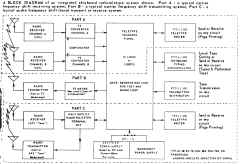
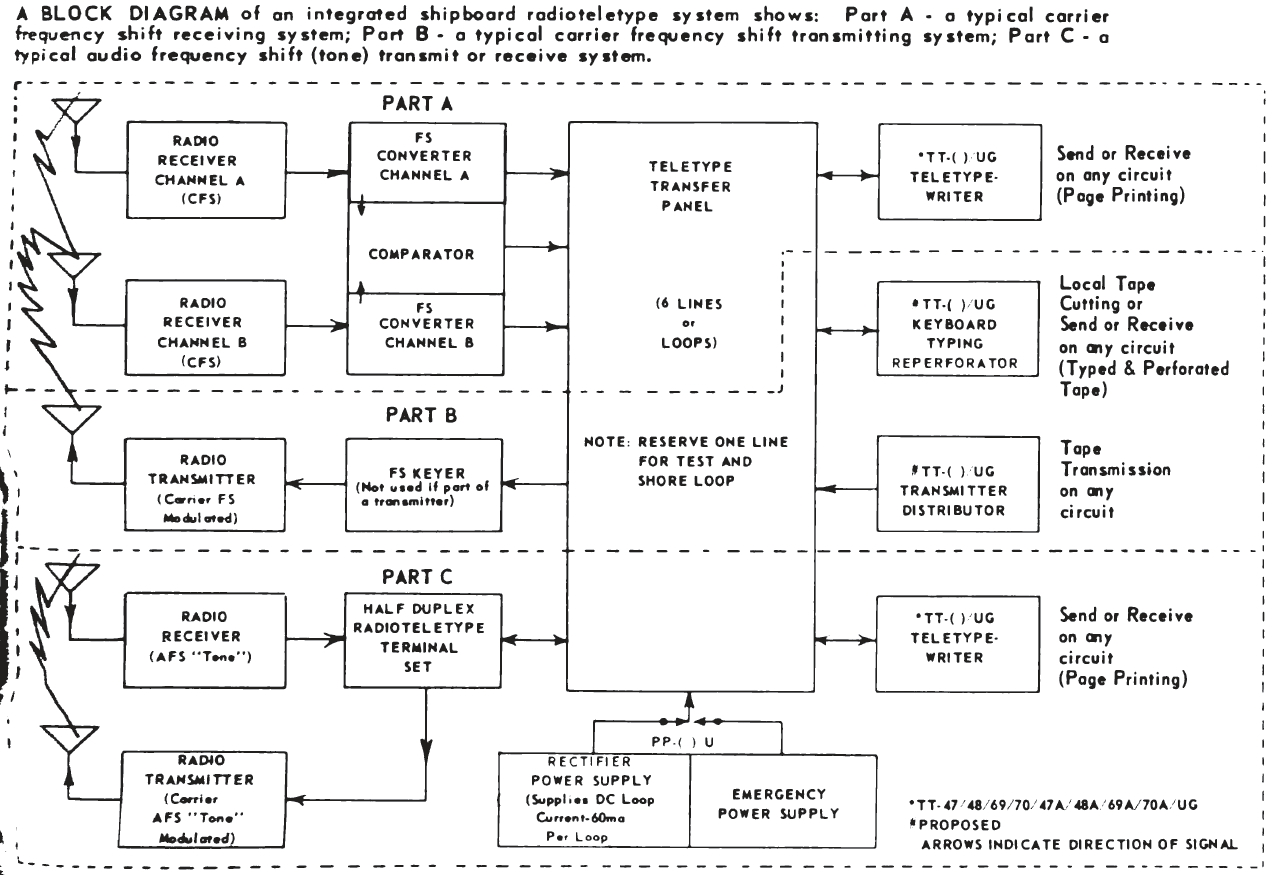
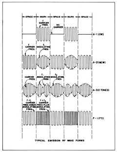
A BLOCK DIAGRAM of an integrated shipboard radioteletype system shows: Part A - a typical carrier frequency shift receiving system; Part B - a typical carrier frequency shift transmitting system; Part C- a typical audio frequency shift (tone) transmit or receive system. |

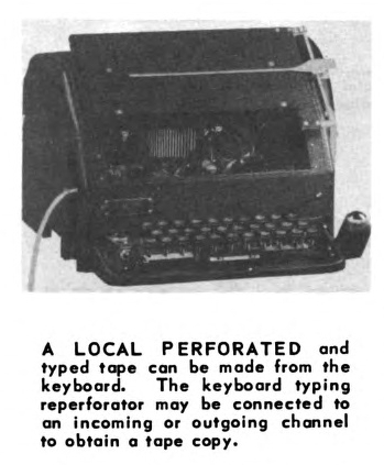
A LOCAL PERFORATED and typed tape can be made from the keyboard. The keyboard typing reperforator may be connected to an incoming or outgoing channel to obtain a tape copy. |

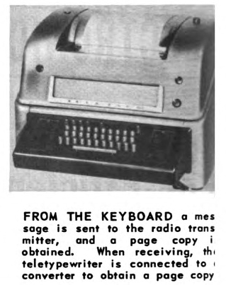
FROM THE KEYBOARD a message is sent to the radio transmitter, and a page copy is obtained. When receiving, the teletypewriter is connected to a converter to obtain a page copy |
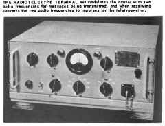
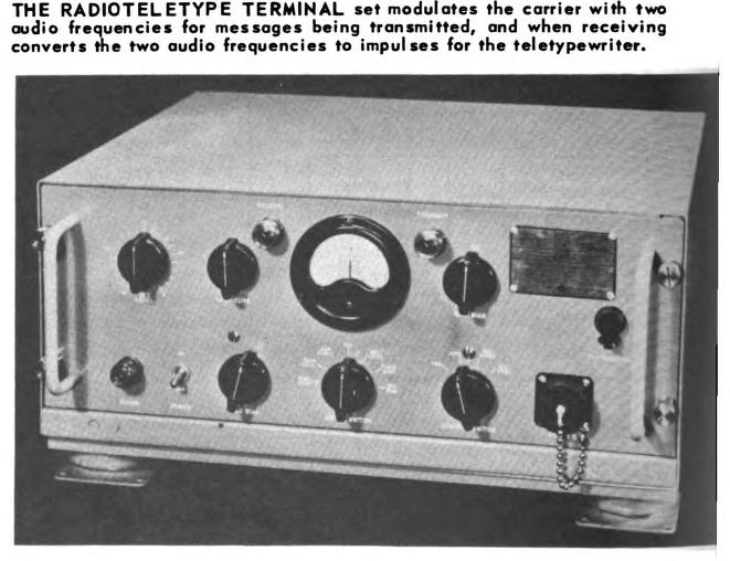
THE RADIOTELETYPE TERMINAL set modulates the carrier with two audio frequencies for messages being transmitted, and when receiving converts the two audio frequencies to impulses for the teletypewriter. |
 |
 |
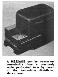
A MESSAGE can be transmitted automatically from a previously made perforated tape by means of the transmitter distributor,
shown here. |
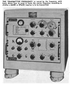
THE TRANSMITTER FREQUENCY is varied by the frequency shift keyer shown here to raise or lower the carrier frequency according to whether a MARK or SPACE impulse is to be transmitted. |
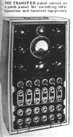
THE TRANSFER panel serves as a patch panel for switching tele-typewriter
and terminal equipment. |
|
-- |
-- |
Radioteletype System Is Used By Navy For Efficient Communications Service
By Fred P. Hall, Electronics Engineer, Bureau of Ships
Prior to World War II, U. S. Naval Radio Communication equipment consisted basically of a transmitter, receiver, and control facilities for them, a hand key, headphones, and a typewriter.
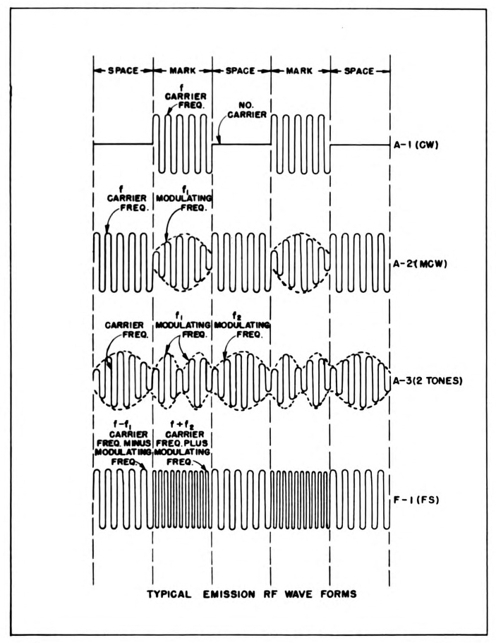
A radioman, proficient in the use of the International Morse Code, was required to operate the equipment. The equipment was capable of CW emission (amplitude-modulated telegraphy, on-off, without use of modulating audio frequency, (A-1) and in some instances telephony or voice emission (amplitude-modulated telephony, double sideband, full carrier, A-3) and reception in the LF, MF, HF and VHF frequency ranges.
The definitions of the types of modulation used in this article are in accordance with the Tele-communication Convention Final Protocol, and Radio Regulations, Atlantic City, October 2, 1947.
To provide ideal operating conditions at large installations, the transmitter, receiver, and control equipments were separated by a considerable distance. The control station was linked to the transmitter and receiver stations by VHF radio transmitter and receiver equipment. In smaller installations, particularly on ships, the control and receiver equipments were usually grouped together in one location, and the transmitter equipment in another location. Metallic conductors connected the two groups of equipment. Control switchboards and extensions provided for the individual control of any transmitter and receiver.
System Grows In Use
Neutral d-c or audio impulses on an on-off basis in the International Code contained the keyed intelligence to the radio transmitter. Keying was accomplished by hand, speed key or by an automatic tape device. The speed of transmission and reception, usually from 15 to 100 wpm, depended upon the ability of the operator, nature of control facilities, characteristics of the automatic devices, and the general prevailing circuit conditions.
Although the teletypewriter had been used successfully on commercial wire circuits for several years, its application to long distance radio communications had not been evaluated for military services. Demonstrations and evaluation of the teletypewriter and its related tape facilities occurred in 1941 at Naval Communication Headquarters, Washington, D. C. At this time the teletype- writer and its five-unit start-stop (Baudot) sequential code, effectively replaced the conventional hand key, headphones, tape keyer, and recorder which had been used for many years with the International Code. The equipment used in conjunction with a radio transmitter and receiver, which provide facilities for semi-automatic and automatic communications, is presently known as Radioteletype Terminal Equipment. The continued use and growth of this system in recent years throughout the Naval service, including ships, is today providing the means for conveying intelligence accurately, rapidly and efficiently.
Letters And Numbers Represented
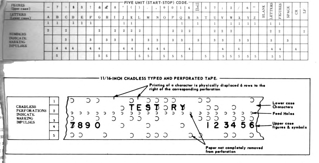
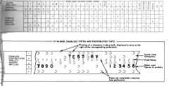
The five-unit start-stop (7.42 units) signaling code of the teletypewriter consists of 32 five-unit code combinations. Twenty-six of the code combinations represent the characters of the alphabet which appear in lower case and twenty-six numerals or symbols which
appear in upper case. In addition to the twenty-six code combinations, there are six function control combinations, each of which forms a special function necessary to accomplish mechanically, the following: line feed, carriage return, space, upper case figures or symbols, lower case letters, and a feed out blank. A total of
62 characters, numerals, symbols, and functions are possible in the teletypewriter.
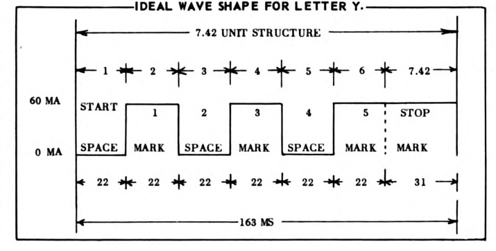
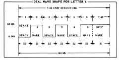
Each sequential code combination consists of a start impulse, five intelligence impulses (vary with the individual character)
and a stop impulse. All impulses 60 wpm speed are of 22 milliseconds duration except that the stop impulse is prolonged an extra 10 milliseconds. During the extra 10 milliseconds the transmitting and receiving mechanisms of the teletypewriter are stopped and locked in readiness for the start of the next character. Approximately 163 milliseconds are required to transmit or receive one character code
combination.
Serves As Typewriter
The local circuit or series d-c loop is keyed opened and closed in accordance with the five-unit start-stop code combinations generated in the teletypewriter, so each letter is assigned a specific sequence of impulses. For example, as the letter "Y" is depressed on a teletypewriter
keyboard, the local d-c circuit is opened (start impulse) which causes the teletypewriter transmitter mechanism to begin a rotation and an operation. Intelligence
impulses are current (closed), no current (open), current (closed), no current (open), current (closed),
followed by a stop impulse (closed). The teletypewriter for 60 wpm speed, performs approximately 368 operations per minute (0PM).
A synchronous or series a-c governed motor, coupled through a gear reduction to the transmitting and receiving rotating mechanism in the teletypewriter, provides the constant speed that is necessary to maintain synchronization between a sending and a receiving teletypewriter. The teletypewriter transmitting and receiving circuits are usually connected in series in the d-c loop so that a local copy can be obtained during the time that the teletypewriter is transmitting. Through the medium of a central switchboard with a common rectifier supplying line or loop currents, the teletypewriter transmitter contacts and receiving selector magnet coil are connected to an outgoing send channel, or to an incoming receive channel of a radio circuit. In this way the teletypewriter serves as a typewriter, copying outgoing as well as incoming messages.
Audio Frequencies Converted
During World War II equipment was developed for use with a radio receiver to permit "Radio Carrier Frequency Shift" (frequency or phase modulated telegraphy without the use of modulating audio frequency, i.e. frequency shift keying F-l) transmission and reception of the five-unit start-stop code. These equipments are generally known as frequency-shift exciter and frequency-shift converter units.
The frequency shift keyer or exciter unit effectively replaces the oscillator in a CW radio transmitter. It provides a means for shifting the oscillator frequency of a transmitter above and below a calibrated frequency. The total amount of shift is adjustable from 0 to 1000 cps. Normally, the keyer is adjusted so that the shift does not exceed plus and minus 425 cps, or a total shift of 850 cps from some assigned output frequency of the transmitter. The d-c impulses derived from a teletypewriter loop and introduced into the frequency shifter unit cause the output carrier frequency of the transmitter to increase (MARK) for a current (closed) impulse and decrease (SPACE) for a no-current (open) impulse.
The frequency shift converter is used to convert the two audio frequencies, derived from the radio receiver output, into direct current impulses suitable for operating the selector magnet of a receiving teletypewriter. Of the two audio frequencies present in the receiver output, the MARK frequency
corresponds to the radio carrier frequency plus 425 cps and the SPACE frequency corresponds to the radio carrier frequency minus 425 cps. The MARK and SPACE frequencies are converted to d-c impulses which form a current (closed) and a no-current (open) condition suitable for receiving teletypewriter circuits.
The main advantage of the carrier frequency shift method of transmission and reception is the ability of the radio transmitter to maintain a constant power output during the transmission of marking and spacing impulses comprising the intelligence. Hence the carrier wave of a transmitter produces a constant level of high frequency voltage at the input of a distant receiver. In some installations, to overcome selective fading, two radio receivers in space diversity are used with their antennas separated by a nominal distance. In other instances, where the transmitting station keys two transmitters each on a different frequency, two receivers are used in frequency diversity. The audio output of one radio receiver is fed into one converter unit and the
output of the other receiver to another converter unit. The comparator unit determines which of the mark or space frequencies from the converter units is of the better quality and converts that signal to direct current impulses suitable for operating the receiving mechanism in a teletypewriter.
Terminal equipment to permit the radio carrier-frequency shift method of transmission and reception generally known as "Tone Modulation" (amplitude modulated telegraphy by keying of a modulating audio frequency or audio frequencies, or by keying of them modulated emission, A-2), is
generally associated with a radio transmitter and receiver in the VHF and UHF frequency bands. Tone modulation may be used on amplitude modulated telephony, double side band (full carrier, A-3). The terminal equipment is not restricted in its use to equipment in the above bands, however. It may be used with equipment in lower frequency bands which are capable of A-3 type operation.
Method Is Simple-Compatible
This method requires a radio transmitter and receiver, a one-way reversible (send or receive) tone terminal, and teletypewriter. The teletypewriter provides the keying in accordance with the five-unit start-stop code combinations. The current (marking) and no-current (spacing) impulses of code combinations from the transmitting mechanism in a teletypewriter are converted in the tone terminal to two audio frequencies. The highest represents a current impulse and the lowest a no-current impulse. These audio frequencies are injected into the voice modulating stage of the radio transmitter. In reverse order, the two audio frequencies derived from the receiver output are injected into the receiving station terminal where they are converted into d-c impulses suitable for operating the receiving magnet coil of a typewriter.
The main advantage of this method is its simplicity and compatibility in control and switching circuits with other audio and voice circuits.
A rapid and efficient means of radio communications, carrier frequency shift and audio frequency shift transmission and reception, using the five-unit start-stop code, are presently used for broadcasts to ships, between ships, and from ship to shore stations.