FREQUENCY SHIFTER KEYER KY-30/GRT
Purpose
Frequency shift keying is used principally for long-distance communication in the higher frequencies (3 mc to 30 mc). The keyer can be connected to different types of Navy transmitters, and is arranged so that closing the contacts of a telegraph key or teletypewriter produces a mark (tone on) signal. This causes the transmitter to emit a frequency above the mean assigned frequency of the transmitter. Opening the contacts of a telegraph key or a teletypewriter produces a spacing signal (tone off), which causes the transmitter to produce a frequency below the mean frequency of the transmitter. Upper and lower values of the shifted frequency are adjusted to be located symmetrically above the assigned transmitter frequency (above and below the carrier by about 425 cycles, if the total shift is 850 cycles).
The frequency shift keyer ordinarily is used at the transmitting station of a radiotelegraph circuit. Telegraph signals are generated at a control point equipped with teletypewriter keyboards, tape transmitters, or a hand telegraph key for frequency shift transmissions. At the receiving terminal the frequency-shifted signals are copied by an operator (in the case of hand-sending), or they serve to actuate a teletypewriter, reperforator, or tape recorder. Both the transmitting and receiving radio stations may be remote from communication centers and ordinarily are connected to the stations by wire circuits.
Operating Frequencies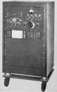
The radio-frequency output of Keyer KY-30/GRT (fig. 9-25) is in the range 1000 to 6700 kilocycles. This frequency is shifted upward or downward a small amount to produce r-f telegraph signals corresponding to the d-c polar or neutral signals connected to the keyer. The difference between the upper and lower r-f shifts is commonly about 850 cycles. Total shift, however, can be set for values ranging from a few cycles to 1000 cycles. The r-f output circuit of the keyer is designed to be connected to the power amplifiers of a radio transmitter.
The keyer requires a radio-frequency carrier between 0.8 and 6.5 mc, which must be approximately 200 kc lower in frequency than the assigned mean carrier frequency of the transmitter. The carrier can be obtained either from the oscillator included in the keyer, or from an external oscillator, which can be the master oscillator or crystal-controlled oscillator of the associated transmitter.
Equipment Arrangements
Keyer KY-30/GRT is mounted on a horizontal chassis with a 15-1/2 by 19 inch panel (fig. 9-25). All controls necessary for normal tuning and adjustment are located on this front panel. Controls not requiring adjustment during normal operation are located at the rear of the chassis. Fuses and receptacles for attached cable assemblies are also on the rear of the chassis. A temperature-controlled oven which contains the 200-kc oscillator and its components is located on the horizontal chassis. Also included in the oven are the keyer tube circuits and phase-shifting amplifier circuits which are necessary to bring about frequency shift operation of the 200-kc oscillator. The oven includes mountings for three crystals. The
radio-frequency circuits which mix the injection voltage and the 200kc oscillator voltage and amplify the output of the mixer are located in shielded compartments to prevent interaction. A 5-gang tuning capacitor provides simultaneous tuning of all circuits within operating range of the unit.
The radio transmitter at the transmitting station is equipped with a connector panel which can be used for connections among different types of frequency shift keyers. The connector panel contains coaxial jacks, power supply, and other receptacles which correspond to those of the KY-30/GRT. The keyer can be associated quickly with other components of the system by connecting six patching cable assemblies. These six connections provide a primary power supply to the keyer and complete the input, output, and test connections.
Operation
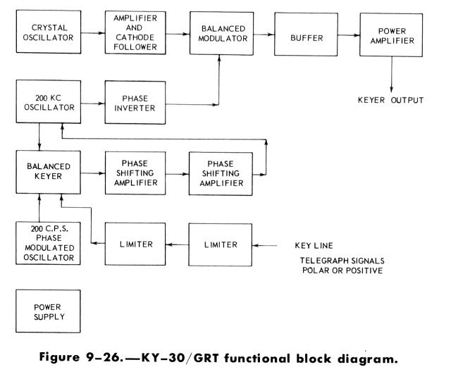
Principle of operation of the keyer is suggested by the functional block diagram, figure 9-26. The r-f input to the keyer may be that from an oscillator associated with a Navy transmitter or that of the crystal oscillator of the keyer. The keyer oscillator is equipped with three crystals, any one of which may be selected by a crystal selector switch. Input to the keyer must be in the frequency range 0.8 to 6.5 mc, which is 200 kc less than the output frequency. Frequency of a 200-kc oscillator is raised and lowered a small amount in response to mark and space telegraph signals, and is added to the radio-frequency output of the transmitter or keyer oscillator in the balanced modulator. The transmitter or keyer oscillator frequency thus is balanced out. Only the sum and difference frequencies, resulting from mixing the keyer input and the 200-kc oscillator output, are present in the output of the balanced modulator. The plate circuit of the modulator is tuned to the higher or sum frequency, thereby eliminating the difference frequency.
Components of the crystal oscillator, the 200-kc oscillator, balanced keyer, and phase-shifting amplifiers are located in an oven. Temperature of the oven is closely regulated at about 72° C. (161.6° F.).
Output of the balanced modulator is amplified in two stages, consisting of an intermediate amplifier and an output (or power) amplifier. The intermediate stage permits a low output from the balanced modulator, and provides additional filtering of the sideband output. A ganged variable capacitor tunes the output circuit of the balanced modulator, the intermediate amplifier, and the output circuit of the power amplifier stage. The plate circuit of the output amplifier includes an autotransformer for matching the low impedance of the line to the radio transmitter.
Output level is controlled by adjusting the screen voltage of the power amplifier and buffer stages. Tuned circuits of the balanced modulator and the intermediate and output amplifiers are separated into three bands in the ranges 1.0 to 1.9 mc, 1.9 to 3.6 mc, and 3.6 to 6.7 mc. A band is selected by the FREQUENCY RANGE SWITCH.
The keying circuit normally operates on polar signals, or neutral signals. In ordinary cases the negative side of the external keying circuit is at ground potential. A limiter tube prevents negative key line voltage from affecting operation. A second limiter limits the maximum positive signal to the balanced keyer tube to maintain a constant value in spite of variations in amplitude of key line signals.
The form of the output keying voltage may be modified by the series inductance and bridge capacity controlled by the WAVE SHAPING switch. (See fig. 9-25.) It may also be wobbled at about 200 cycles per second by turning on the PHASE MODULATION switch. The amount of phase modulation is varied by adjusting an associated dial. Phase modulation of the transmission may tend to improve reception under some conditions of severe selective fading.
Output voltage from the limiter tube results in mark and space signals, with or without wave shaping and phase modulation, which are coupled to the balanced keyer tube. Full output of the balanced keyer tube, or a fraction thereof, is connected to a 2-stage phase-shifting amplifier through a point on a voltage divider selected by the TRANSMITTER MULT. FACTOR switch.
Output of the phase-shifting amplifier is connected to the 200-kc oscillator, causing the frequency of the 200-kc oscillator to increase a small amount (for example, 425 cycles for a mark signal) or to decrease a small amount (425 cycles, say, for a space signal). The amount the frequency of the 200-kc oscillator is changed depends on the output of the
phase-shifting amplifier. In turn the amplifier is influenced by the input from the balanced keyer tube.
The 200-kc oscillator is a self-excited single-ended type, frequency of which is changed by output of the phase-shifting amplifier and, to a limited extent, by a variable capacitor, CARRIER FREQ. ADJ. Output of the 200-kC oscillator is frequency-modulated by telegraph mark and space signals, with or without superimposed wave shaping and phase modulation. This frequency-modulated 200-kc oscillator output is combined in the balanced modulator with the output of the transmitter (or keyer) oscillator.
The keyer has a rectifier power supply circuit which produces a low-voltage a-c heater supply, a positive 400-volt plate supply, a positive 250-volt plate supply, a regulated positive 150-volt supply, and a negative 45-volt bias supply.
