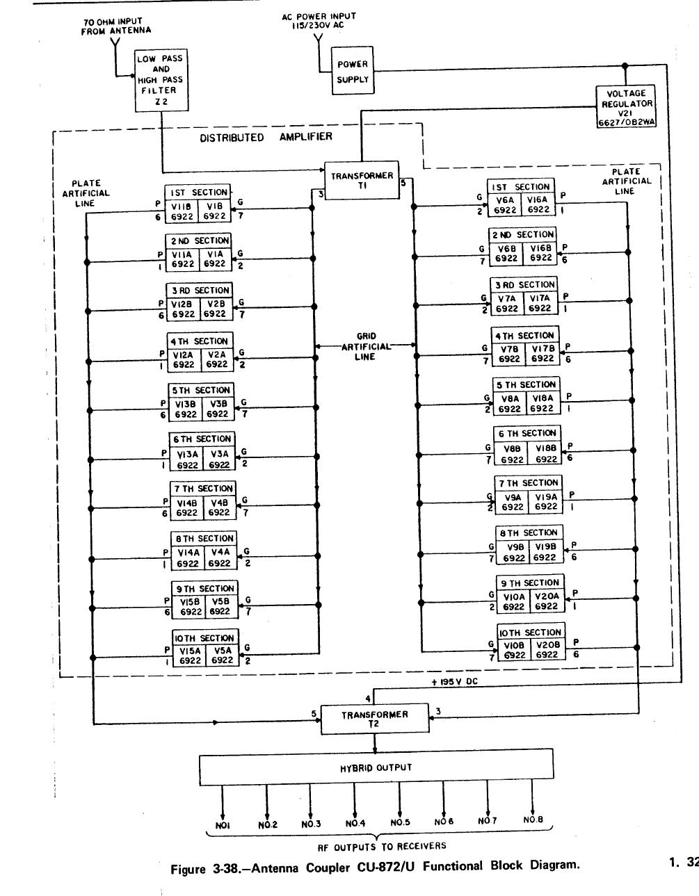
Additional outputs from the same antenna are possible by connecting an output from a primary multicoupler to the input of a secondary multicoupler in a cascade (cascading is discussed below) arrangement as shown in figure 3-38. A functional block diagram of the CU-872/U multicoupler is shown in figure 3-38.
A 70-ohm input impedance is provided to match the impedance from the antenna. From the input connector, the signal is fed to low-pass/high-pass filters. These filters pass only the frequencies in the spectrum between 2.0 MHz and 32 MHz. Transformer T1 in the output circuit of the low-pass/high-pass filters, provides a transition between the low impedance unbalanced input circuits and a relatively high impedance balanced line. Each side of the balanced line drives one section of the push-pull distributed amplifier.
Tubes V1 through V5 and tubes V11 through V15, and their associated circuitry, comprise one-half of the push-pull distributed amplifier. Tubes V6 through V10 and tubes V16 through V20, and their associated circuitry, comprise the other half of the push-pull distributed amplifier.
The distributed amplifier sections employ cascade stages (discussed below) along artificial transmission lines to obtain amplification over a wide bandwidth. The cascade amplifiers aid in reducing intermodulation by minimizing odd harmonic distortion. Additionally, employment of the distributed amplifier results in an improved signal-to-noise ratio. The distributed amplifier sections drive transformer T2 in a push-pull manner, thereby reducing intermodulation by minimizing even harmonic distortion. The resulting signal, developed across the secondary winding of transformer T2, is applied to a cascaded hybrid network which distributes the amplified signal to eight isolated outputs.