Manual NAVSHIPS 94933 - download
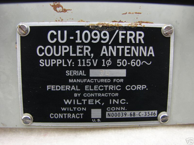
ANTENNA COUPLER CU-1099/FRR.-The Antenna Coupler CU-1099/FRR is a broadband
transistor RF amplifier which permits up to eight 70 ohm outputs to operate simultaneously
off the same antenna. The unit operates over the frequency range of 2 to 32 MHz, with an input
of 70 ohms. It uses 1/12 of the power (15 watts), one-half the space and is one third the weight of
the CU-872. The units are usually mounted in pairs in a standard 48.26 centimeter (19 inch)
bay using a mounting adapter. Figure 3-39 shows one bay of sixteen CU-1099s and two
CU-872s.
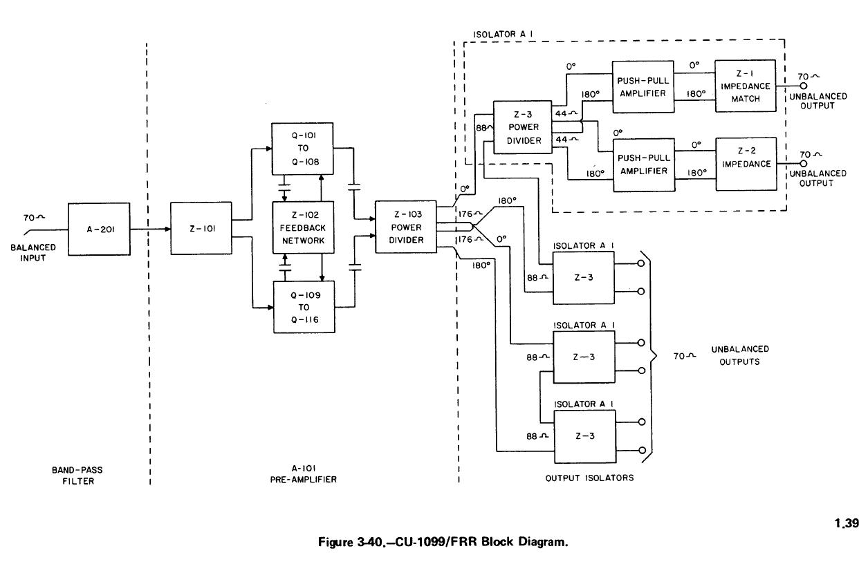
A block diagram of the CU-1099/FRR is shown in figure 3-40. The signal input initially
goes to a bandpass filter, A-201, which is made up of a high-pass and a low-pass filter, aligned to
pass 2 to 32 MHz and attenuate all other frequencies. The bandpass filter output goes to a
preamplifier, which consists of a single class A push-pull stage in which each half of the stage is
made up of eight parallel transistor amplifiers.
A low noise-high frequency transistor used in this configuration, makes possible wideband
operation with a low-noise figure, low circuit impedance and relatively low gain. Push-pull
design is used here, and elsewhere in the coupler, to minimize spurious effects from strong signals
by canceling even-order harmonics and intermodulation distortion products.
There are four output isolator circuits which provide up to 40 dB isolation between receiver
circuits, regardless of the frequency to which a receiver is tuned. The output of Z-103 consists
of two sets of signals 180 degrees out of phase with each other and with 176-ohms impedance
between pairs. Two isolators are connected in series with each output of Z-103, and thus, each
is matched to 88-ohms impedance. 2-3 in each isolator splits its input to match the 44 ohm
input impedance of each of the two push-pull amplifiers in each isolator. The push-pull
amplifiers are made up of four transistors in a single stage, with two parallel transistors in each
half of the stage. The balanced 630-ohm output is converted to an unbalanced 70 ohms by
transformer action. The four plug-in isolator assemblies are mechanically identical, but each is
electrically aligned for the position it occupies. The positions are marked A, B, C, and D with
the B position (J-3 output), being the standard output used in factory alignment.