| 18-17 AN/GRD-6 low band antenna |
18-18 AN/GRD-6 high band antenna |
18-26 AN/GRD-6 operating position |
18-27 AN/GRD-6 function block diagram |
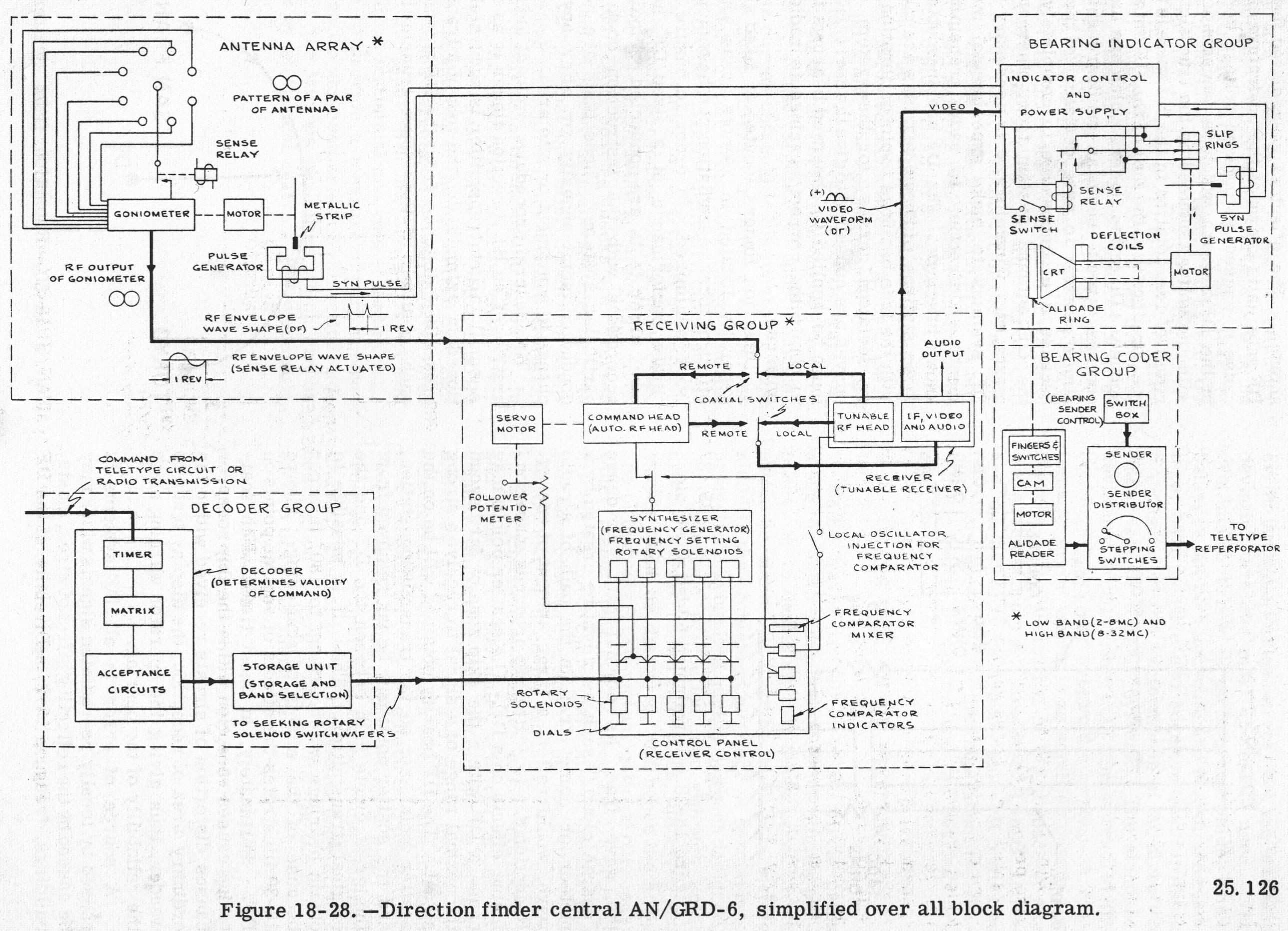
| 18-28 AN/GRD-6 System Block Diagram |
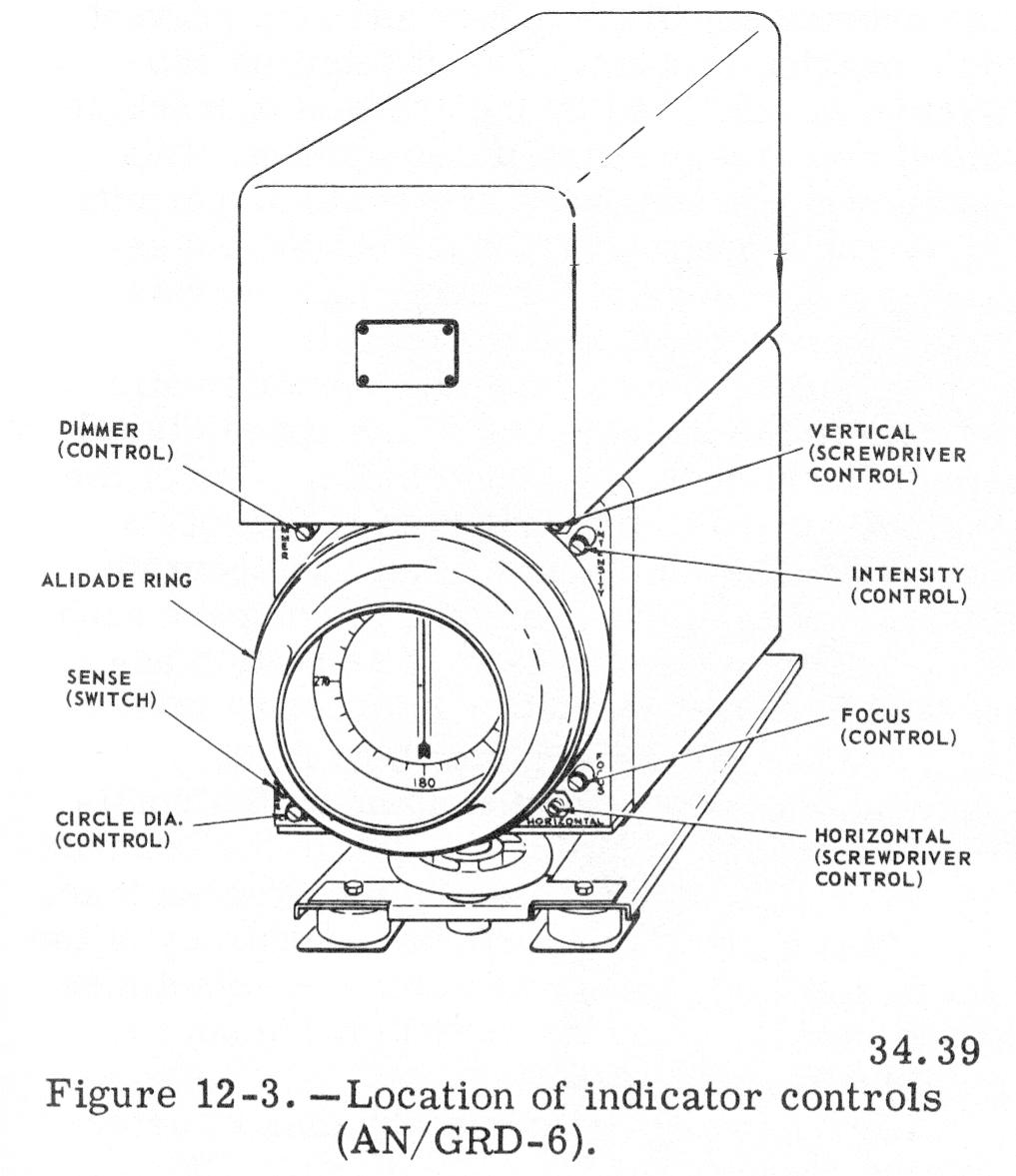
12-3 location of indicator controls |
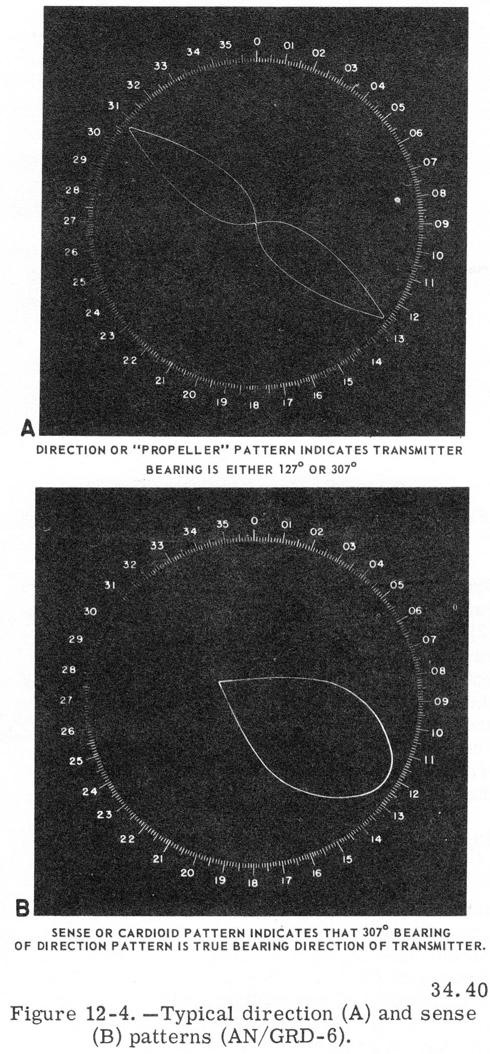
12-4 direction and sense patterns |
|
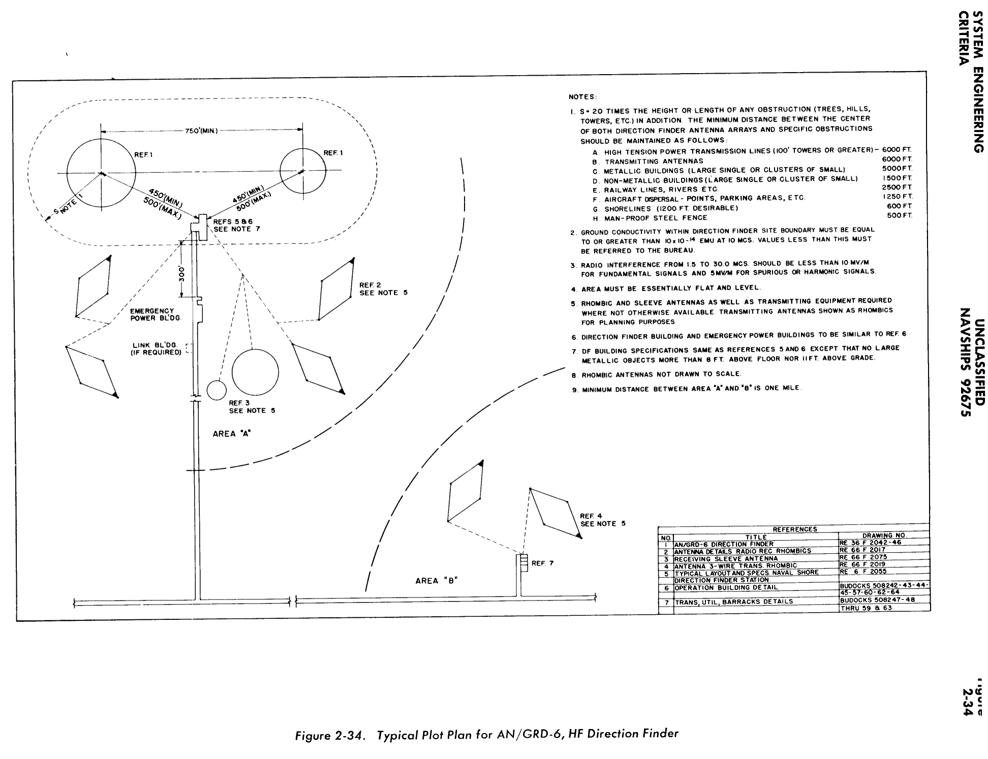
| 2-34 AN/GRD-6 Plot Plan |
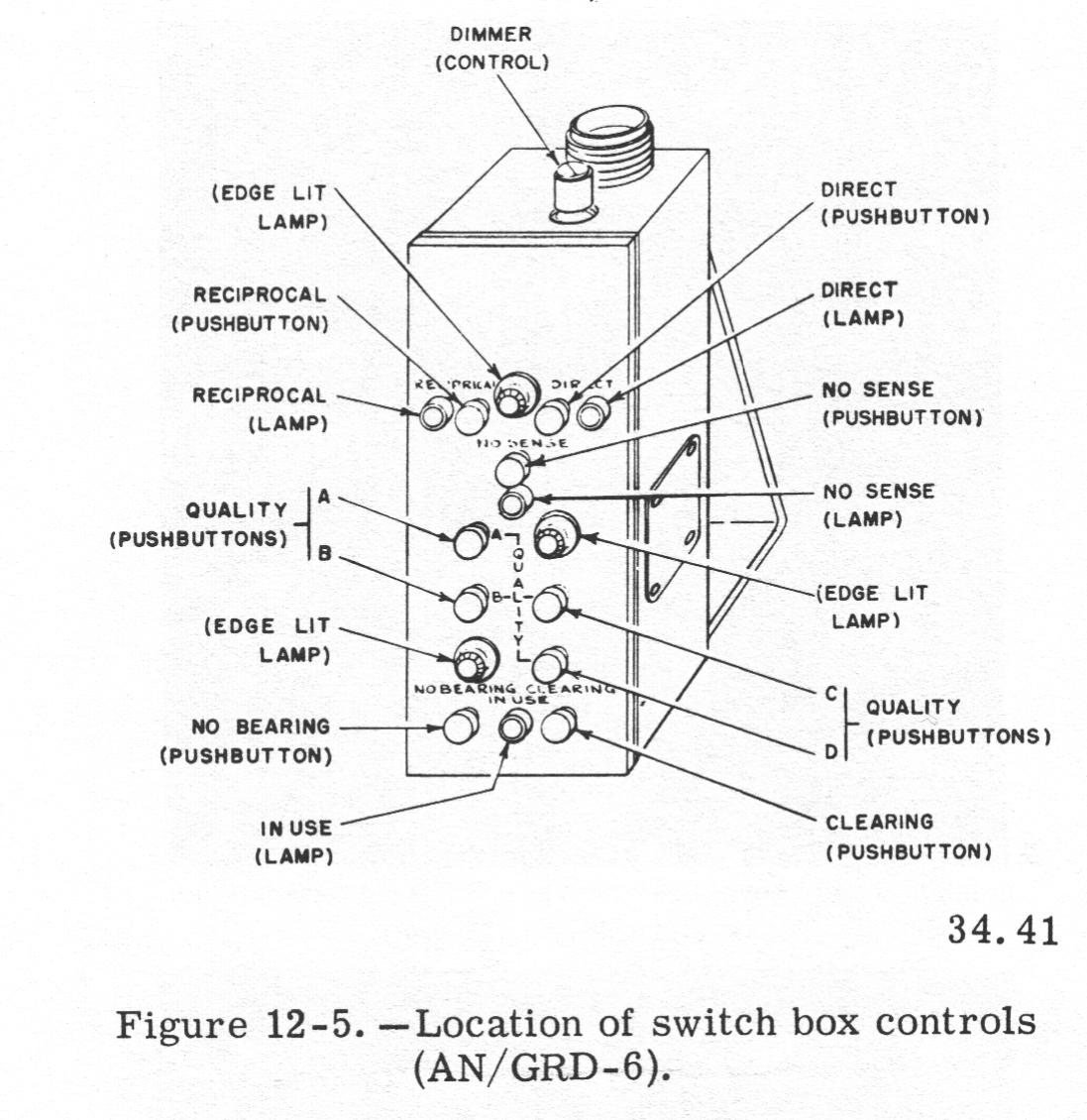
12-5 switch box controls |
||
From a 1964 USN training manual -
ANTENNAS
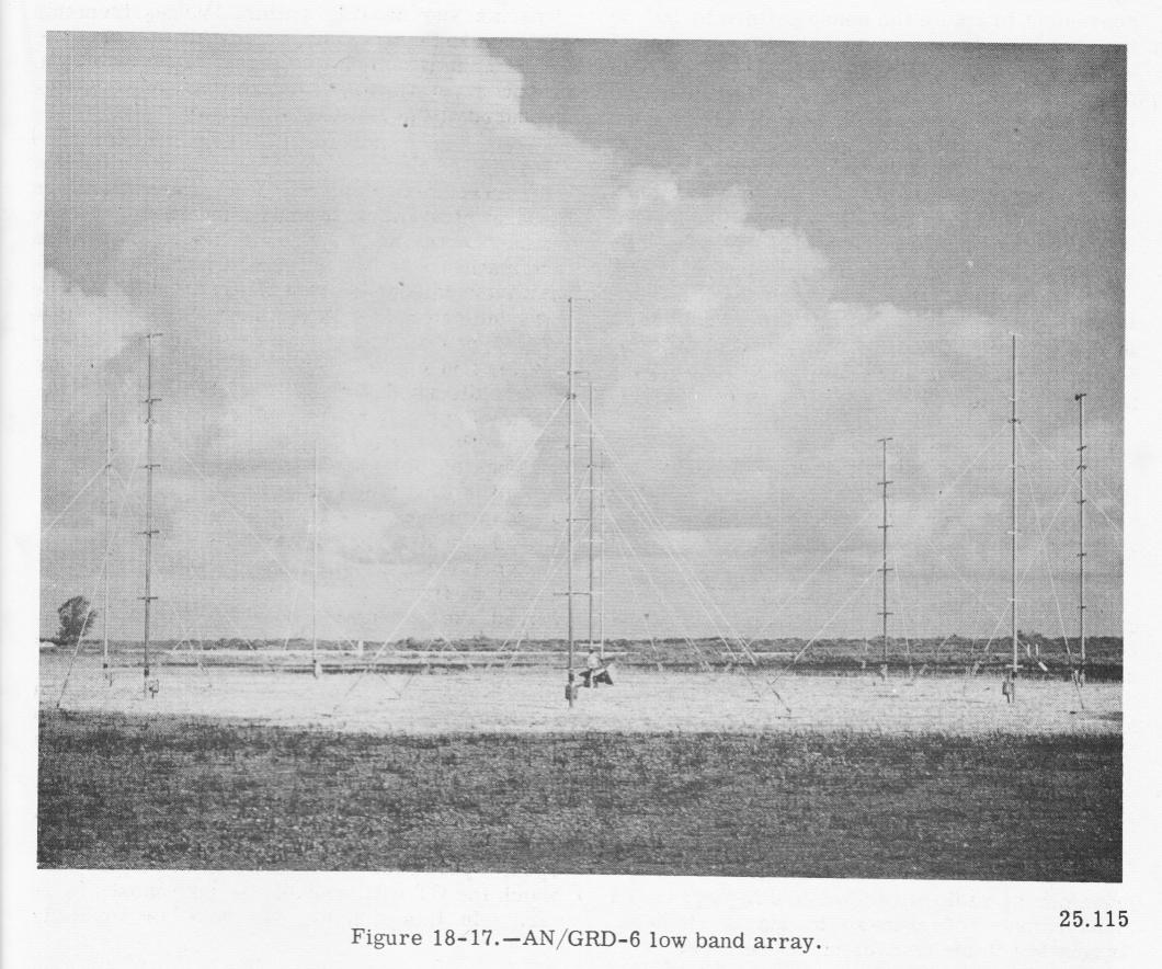
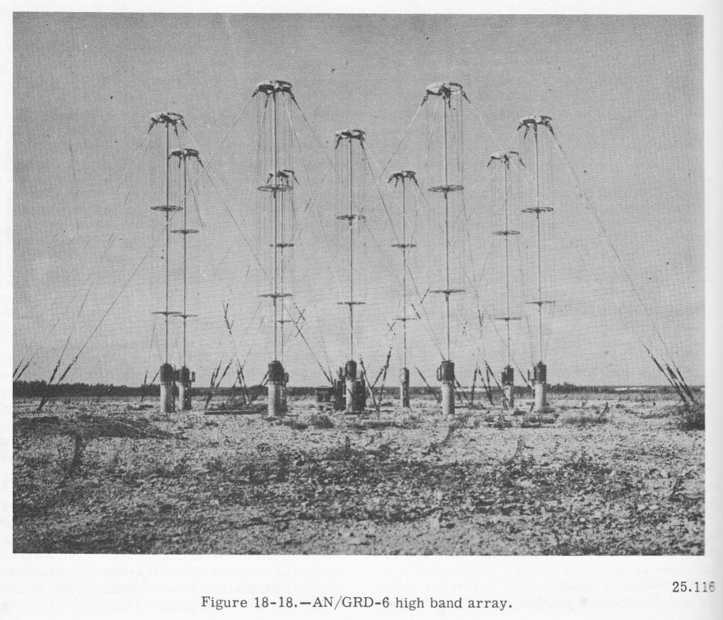
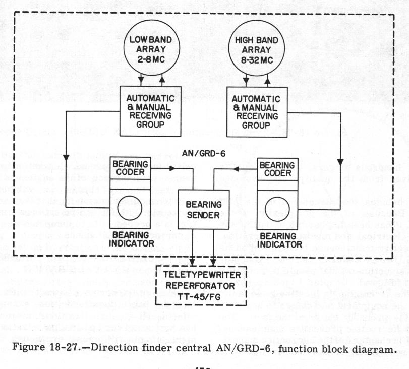
The antennas used with the AN/GRD-6 consist of two arrays; the low band array (2 to 8 mc), and the high band array (8 to 32 mc). Figure
18-18 shows a typical high band array. These antenna arrays are of the U-Adcock type and consist of four pairs of monopoles, equally spaced to form a circle. A ninth element is mounted at the exact center of the array for sense determination.
The low band elements are 27 feet long and are spaced around the circumference of
a circle 100 feet in diameter. The high band elements are 15 feet long, and the circle they form is 25 feet in diameter.
Buried 2 to 4 inches under each antenna array is a circular mat constructed of copper wire mesh. The low band mat is 300 feet in diameter, the high band mat 100 feet. As can be seen by comparing figures, the ground mat extends well outside the arrays. This ground mat reduces polarization error and provides a stable ground system allowing consistent and reliable direction finding performance, independent of local ground conductivity.
RECEIVING AND BEARING INDICATING EQUIPMENT
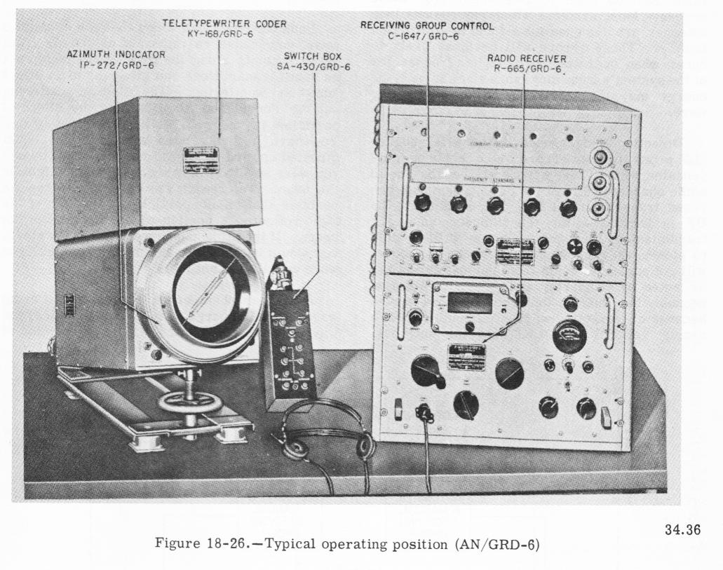
Two receiving groups are used with the AN/GRD-6, one for the low band and the other for the high band. Each performs similar operations for its corresponding frequency band and is almost identical in function and physical appearance. (See figure
18-26). Each receiving group consists of several units but the operator will be concerned primarily with the superheterodyne receivers. The receiver converts r-f signals from the antenna array to suitable deflection current for display on the indicator cathode-ray tube. In addition to the deflection current output for the indicator, the receiver also supplies audio output which may be applied to a loudspeaker or headset.
Both the high and low band indicator groups are composed of an azimuth indicator and an indicator control. The prime function of this group is to provide a visual DF display to the operator on the face of the cathode-ray tube to indicate the direction of arrival of an incoming signal.
EQUIPMENT OPERATION
Any signal within the receiver's frequency range received by the antenna system causes a bearing pattern to appear on the indicator screen. The alidade ring on the indicator is then rotated by the operator until the arrowheaded cursor line bisects the tips of the propeller pattern illuminated on the face of the cathode-ray tube. The direction of the pattern is next determined by depressing the sense switch on the indicator panel (see figure 12-3). This operation replaces the propeller pattern with a cardioid pattern. Figure 12-4A illustrates the propeller pattern and 12-4B the cardioid pattern. If the cardioid or sense pattern is in the direction of the tail of the arrow (leaving the arrowhead clear), the bearing is direct; if the sense pattern is in the direction of the arrowhead, the bearing is a reciprocal. The appropriate pushbutton on the switch box is then depressed. If the sense of the bearing cannot be determined, the "no sense" pushbutton on the switch box is depressed. The
indicator lamp lights after its respective pushbutton has been depressed. One of the quality indicator pushbuttons is next depressed, depending on the quality of the bearing to be transmitted. If a bearing pattern is not present on the indicator screen when attempting to obtain a bearing, the "no bearing" pushbutton is depressed. Figure 12-5 shows the location of the various pushbuttons and controls on the switch box.
The need for accurate bearings cannot be overemphasized. One negligent or careless operator can sabotage the efficiency of the entire HFDF net. The equipment itself has certain features which, if used conscientiously, will help eliminate operator error. One example of this is the arrow etched on either side of the alidade, which, if used properly (as you would use the sights of a rifle) will eliminate parallax. Another feature, although not part of the original AN/GRD-6, is the azimuth mask. The mask is inserted between the alidade and the amber light filter on the indicator and is etched showing the spread of bearings for each
classification of bearing, thus providing an aid to the operator in classifying his bearings. With practice, accurate bearings may be obtained without using the azimuth mask, but remember, accurate and objective bearings and bearing classifications are always desired.