NAVCOMMSTA San Francisco - US Navy Radio NPG


   The U. S. Naval Radio Station at Mare Island was the first naval radio station on the West Coast. This station, commonly referred to as the "Hill Station" was commissioned 27 April 1904. The original site was located on a hill southward of the shipyard proper. An abandoned pigeon cote was moved to the site and fitted up as an operating and transmitting room. In addition to the pigeon cote, one ship type mast, 130 feet high, was erected. [Photo]

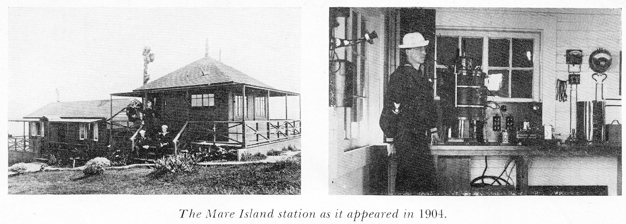
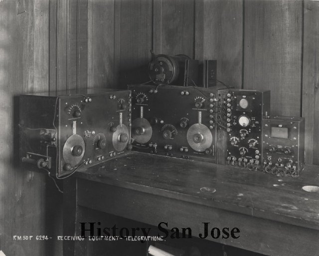
   The first equipment consisted of a Slaby-Arco open-gap spark transmitter together with a Slaby-Arco coherer and decoherer for receiving, which had been purchased from the German General Electric Company and shipped to the Mare Island Navy Yard for installation . The first call sign used was "MI" which was probably self-assigned as the first officially assigned call sign was "TG".

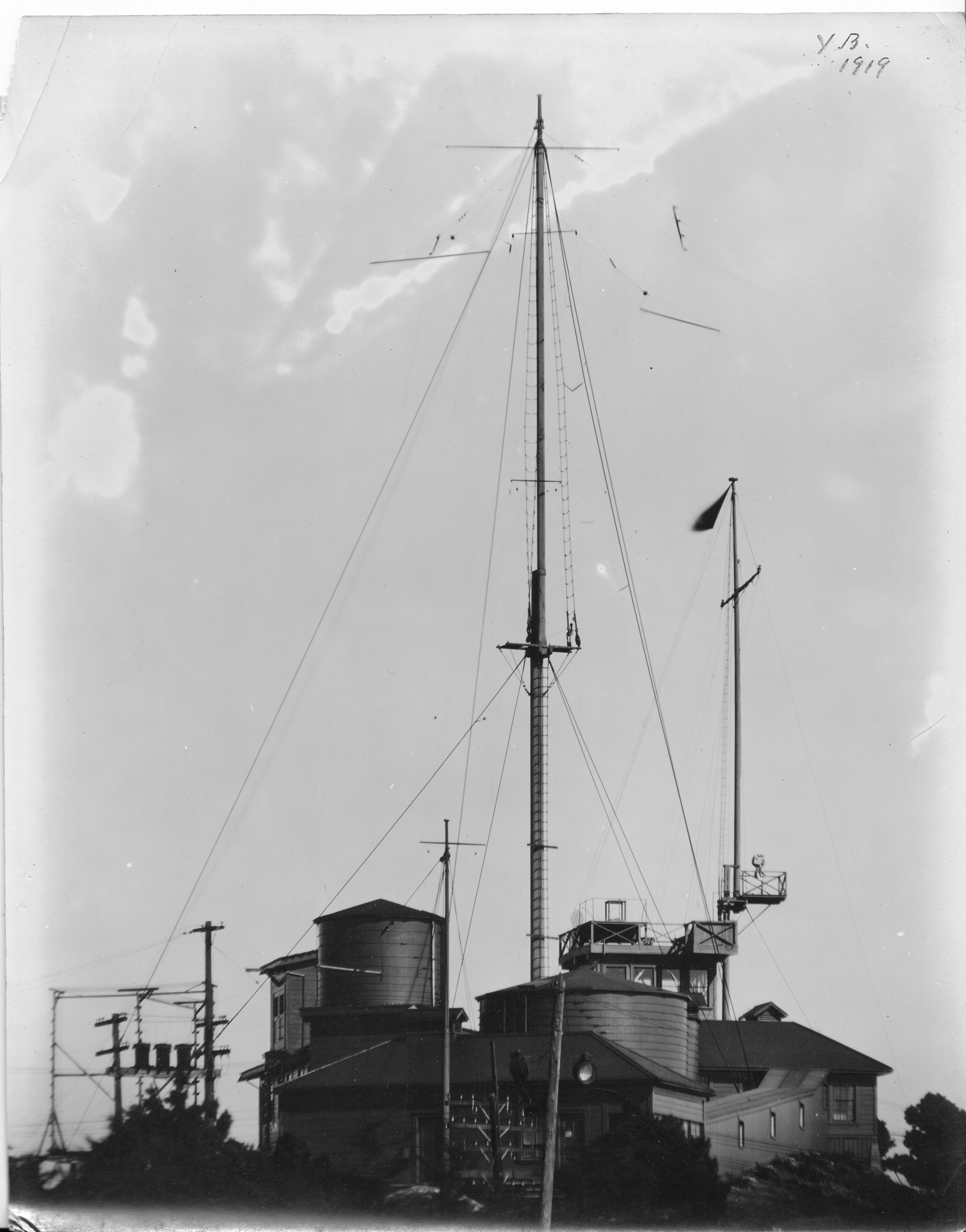
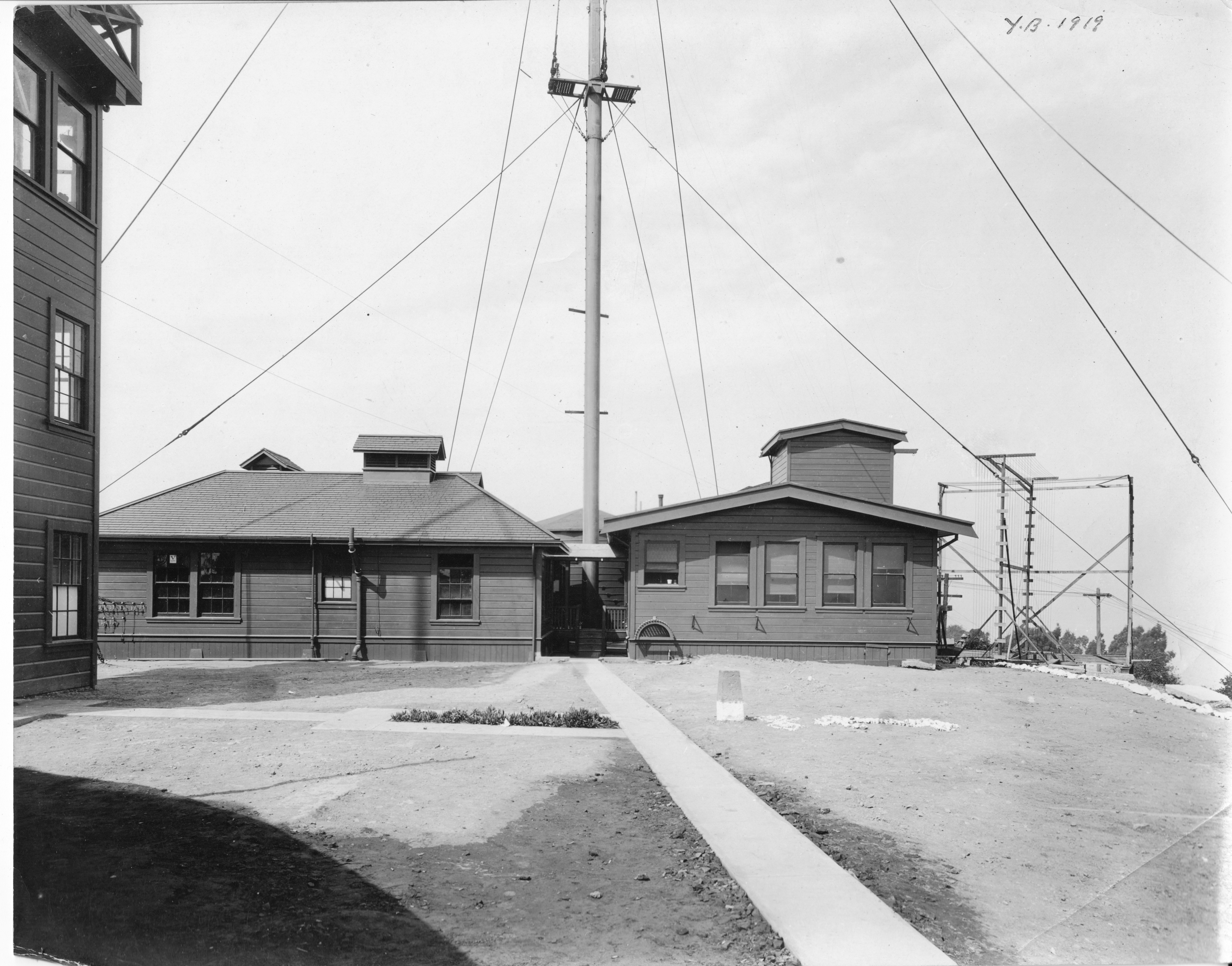
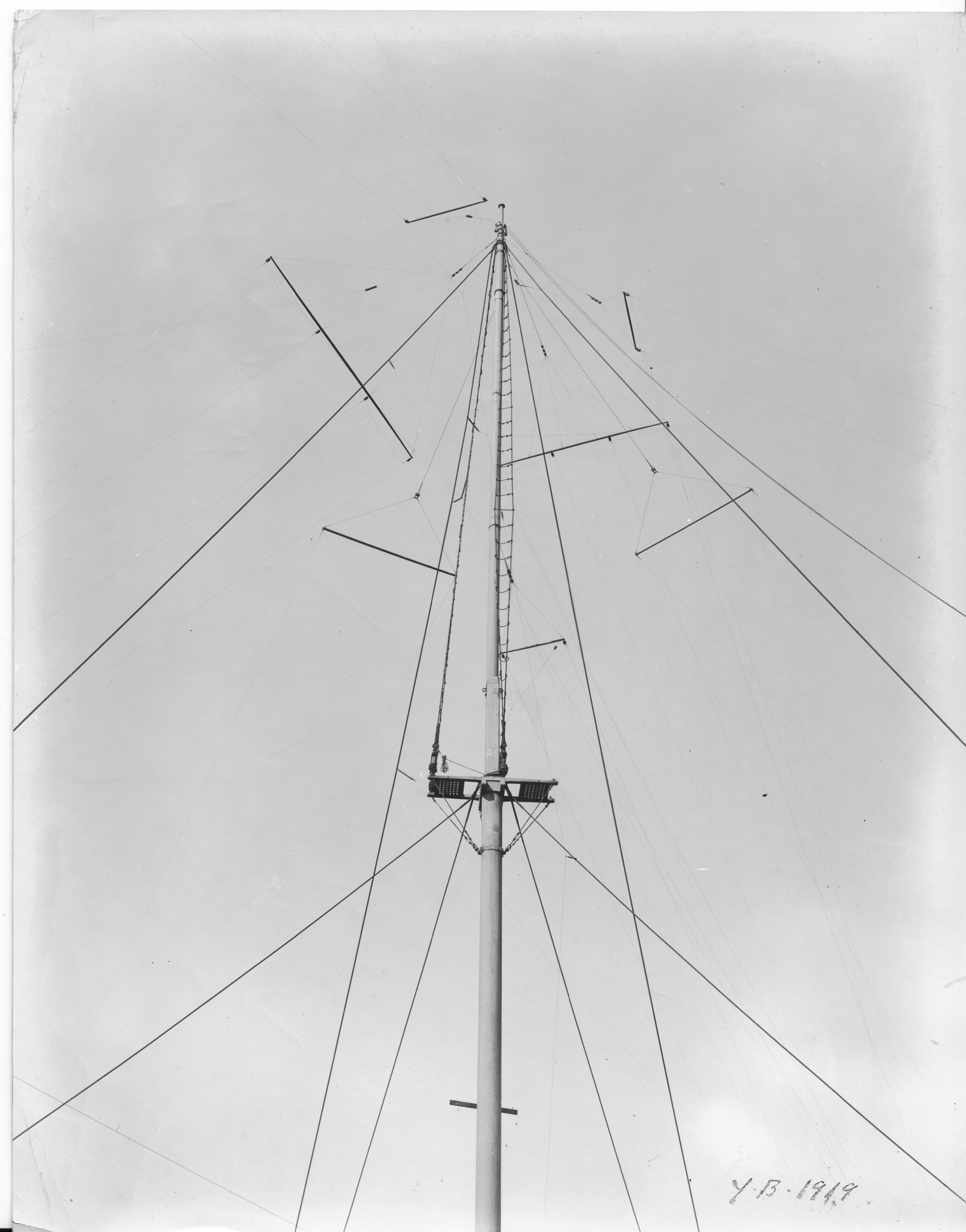
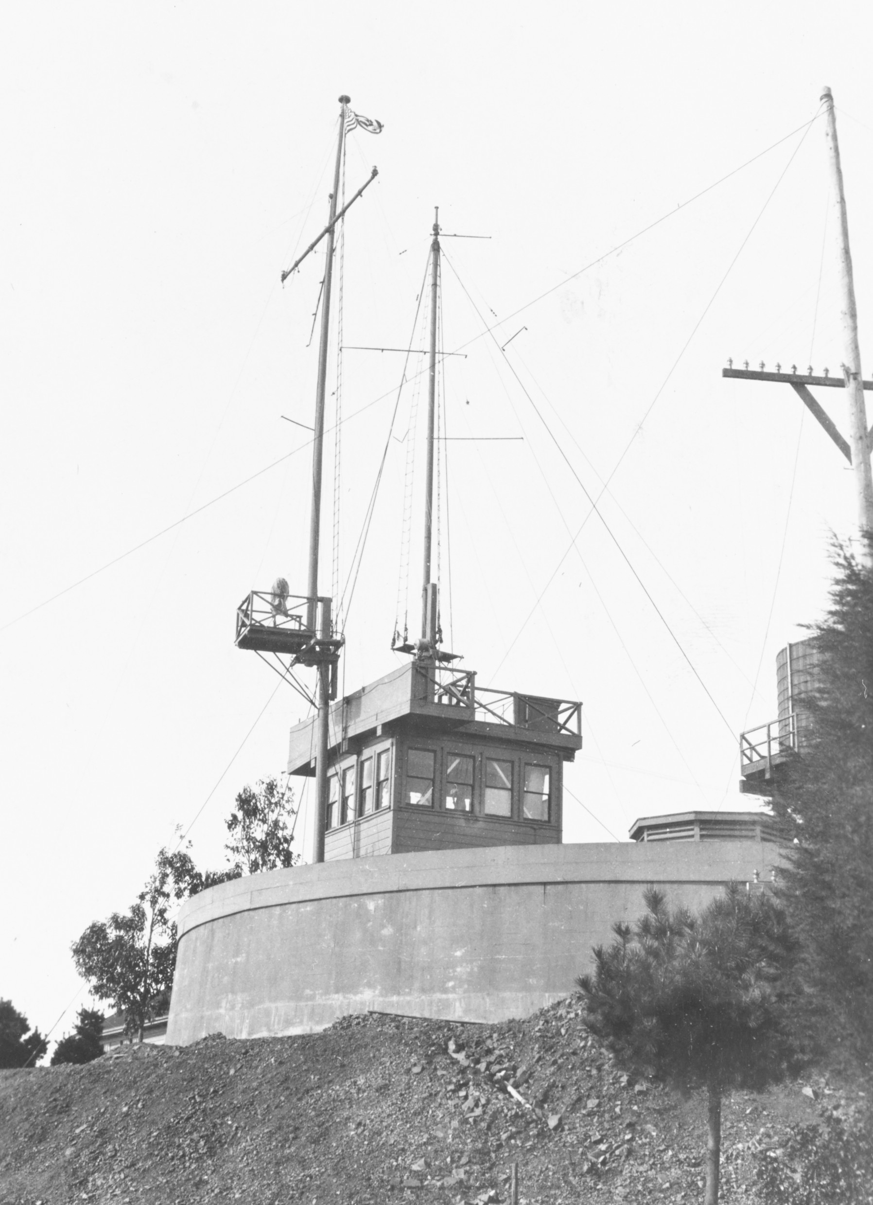
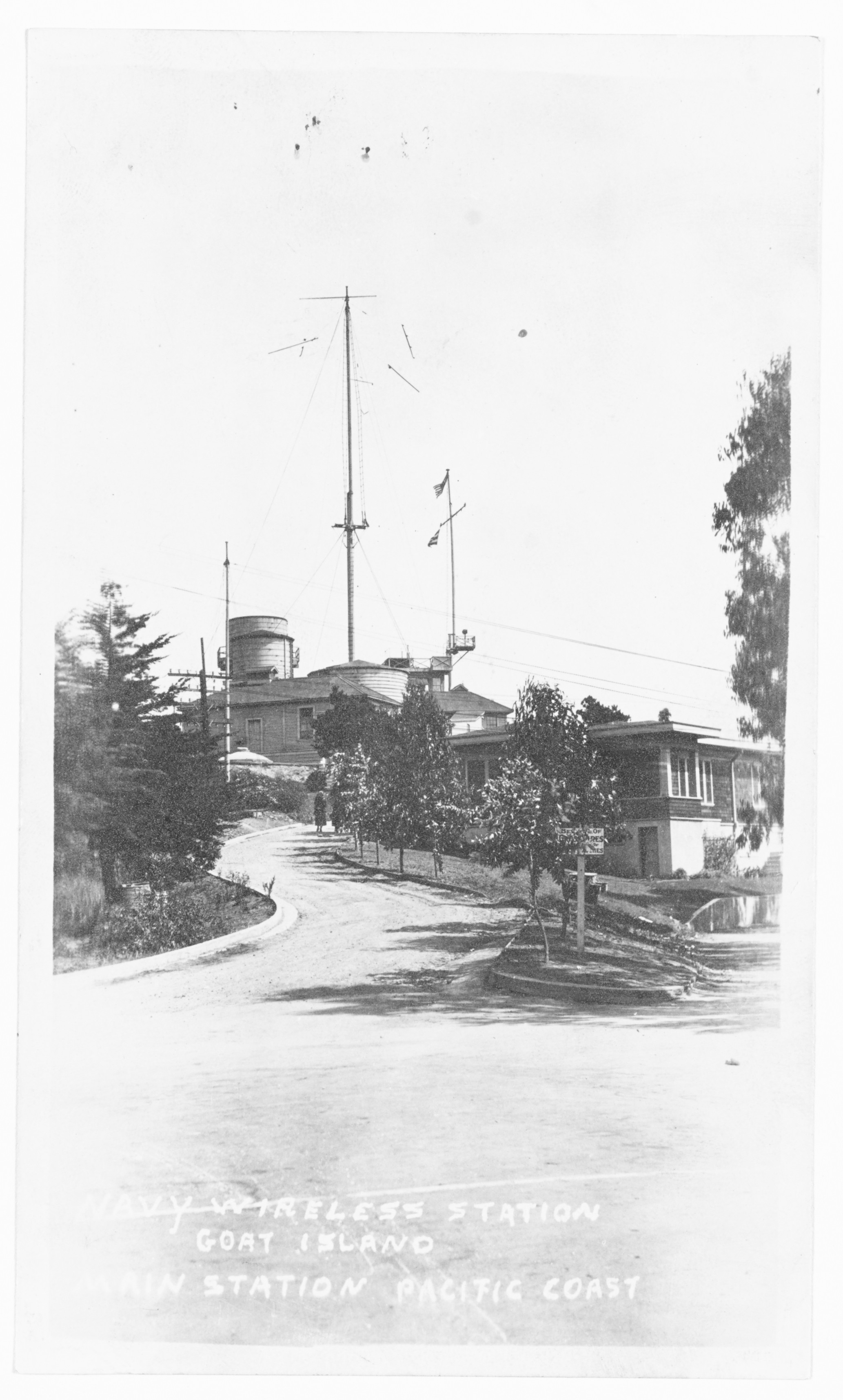
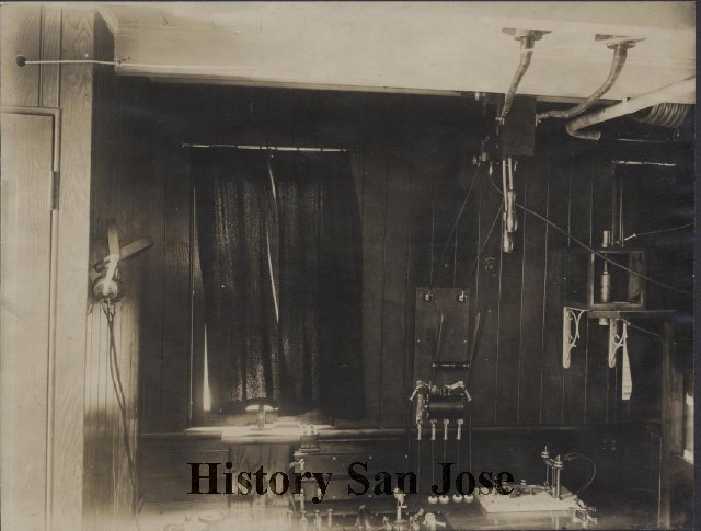
   The Yerba Buena station (Goat Island) was commissioned May 5, 1904. The first official call sign was "TI." [Photos]

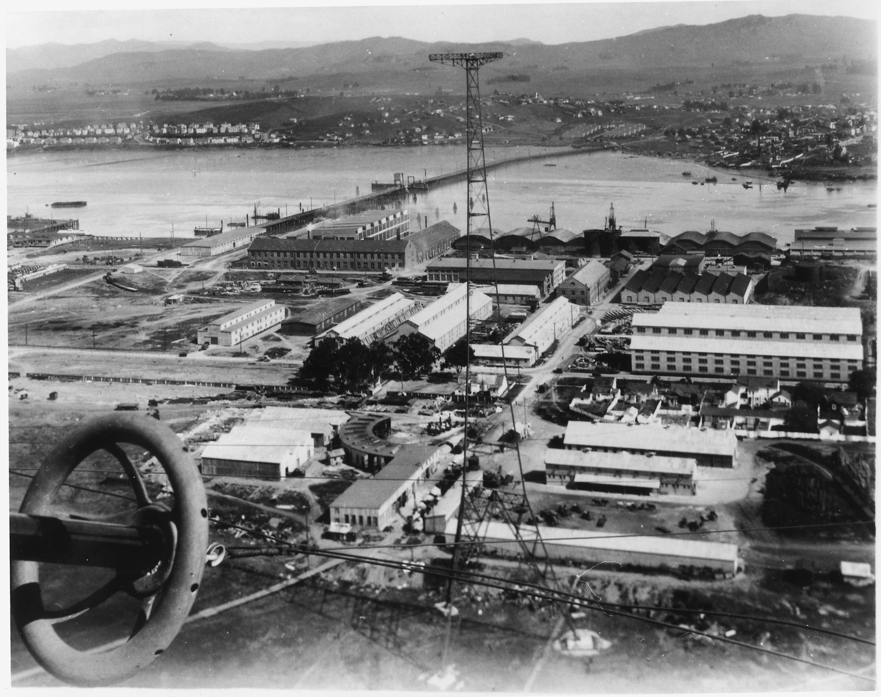
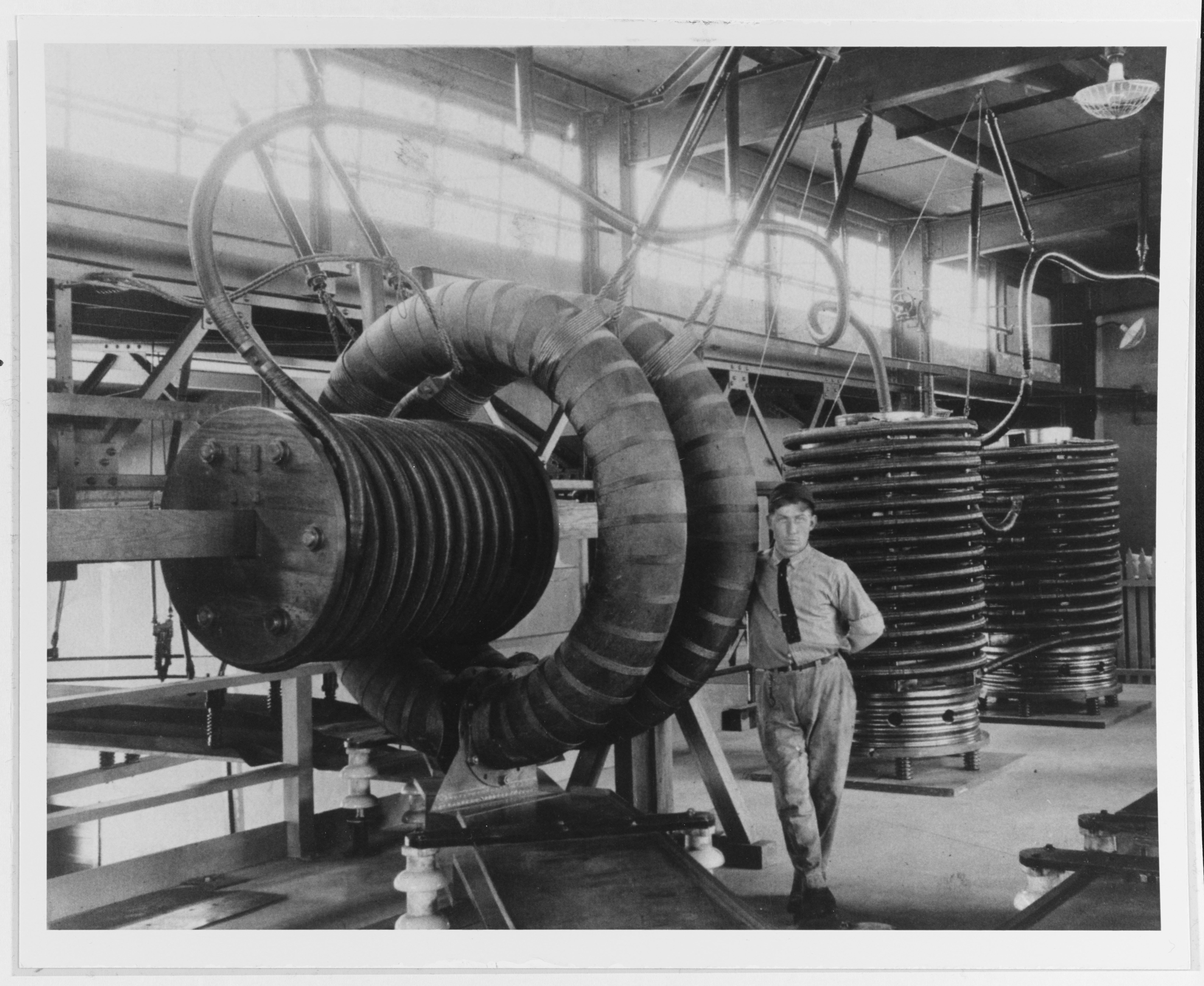
   In 1915, 30 KW arc transmitters were installed at Mare Island. A decision was made to establish the Yerba Buena Station as the control station and Mare Island as the transmitter station for the communication complex. At that time the Mare Island station was changed from a transmitting/receiving station to a transmitting station only, with control (keying) of the transmitters accomplished by the Yerba Buena Station (NPG). The San Francisco District consisted of the stations at Yerba Buena Island (District Center), Mare Island, Farallon Island, Eureka, Marshfield and a station at Monterey which had been authorized but was never built.

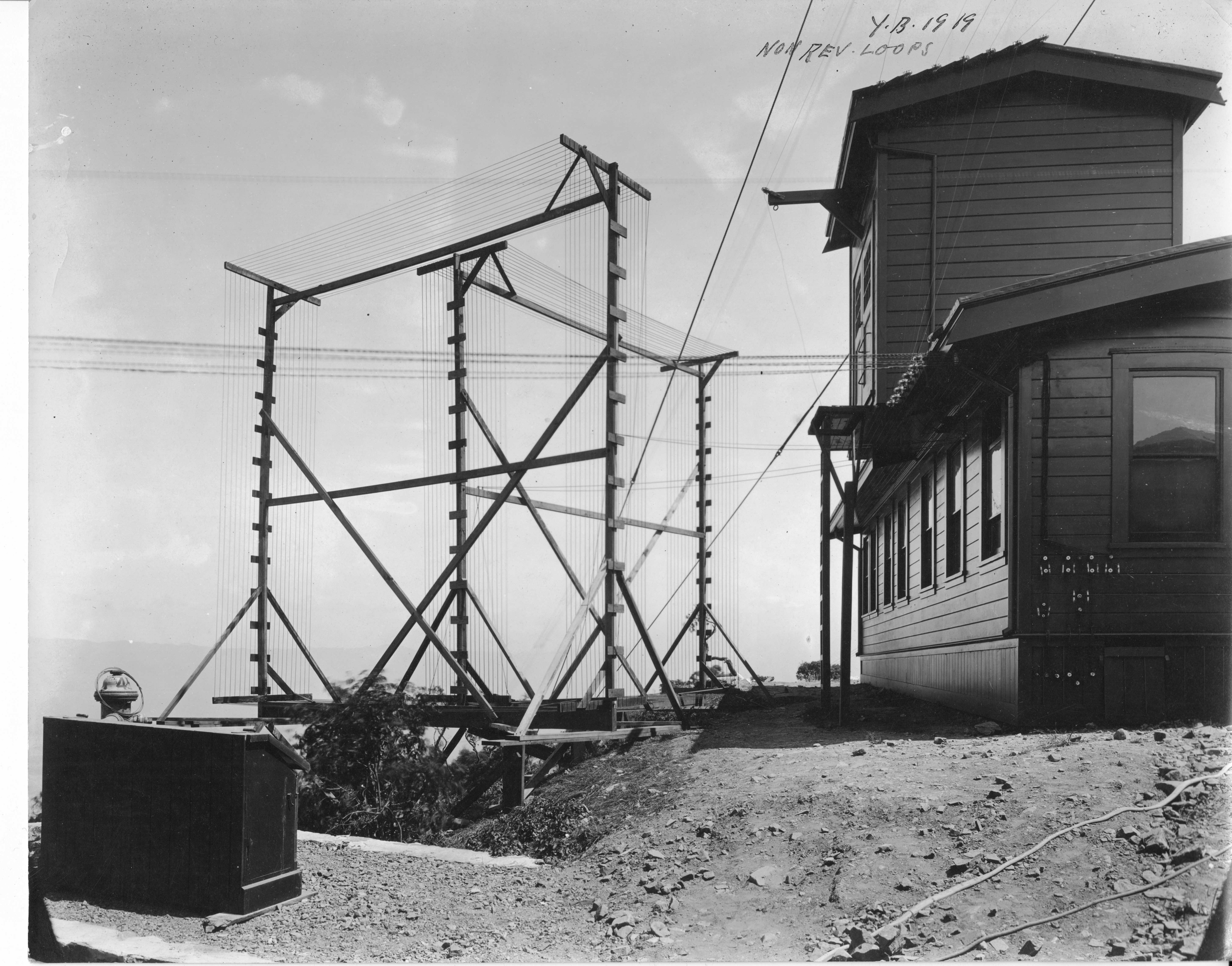
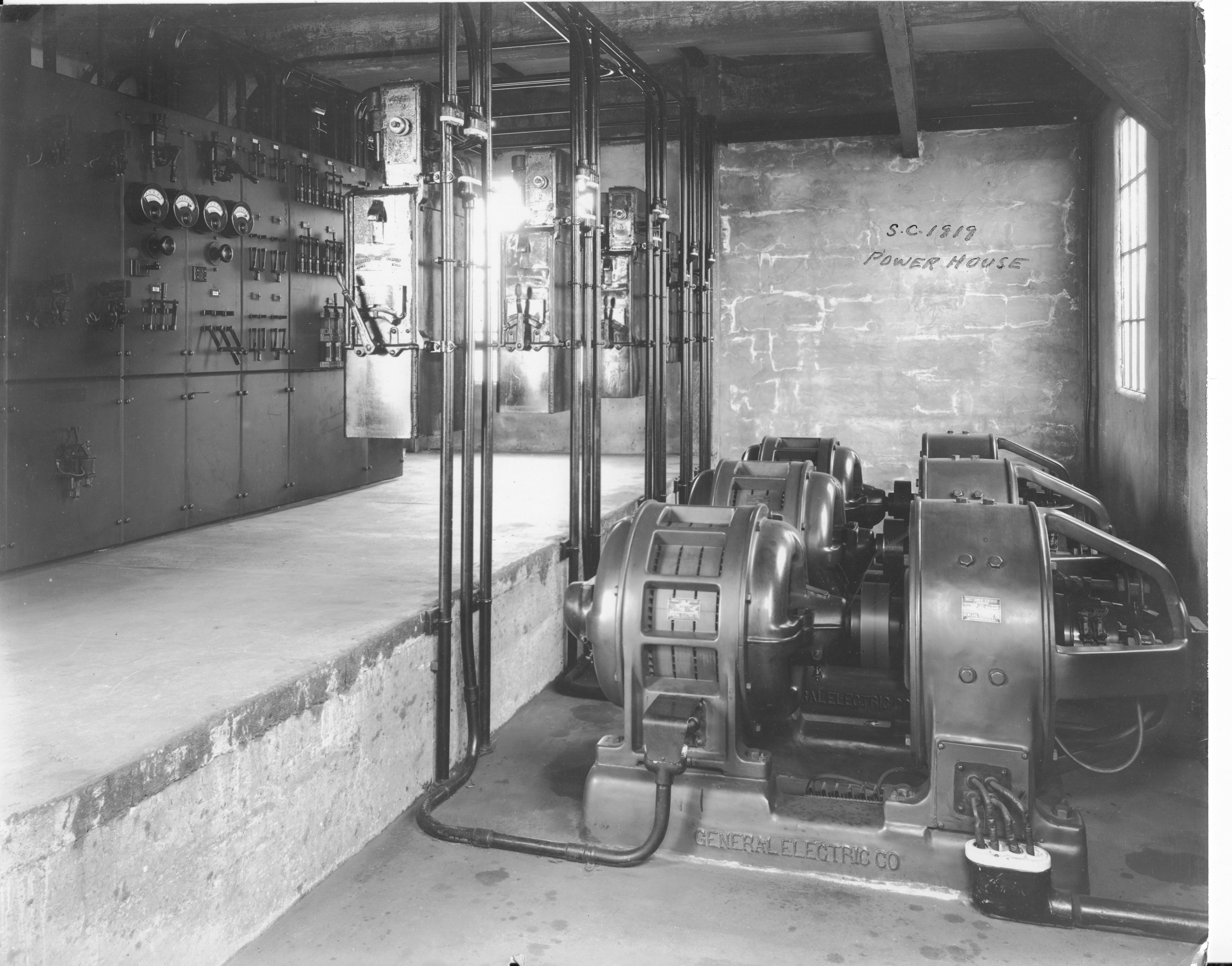
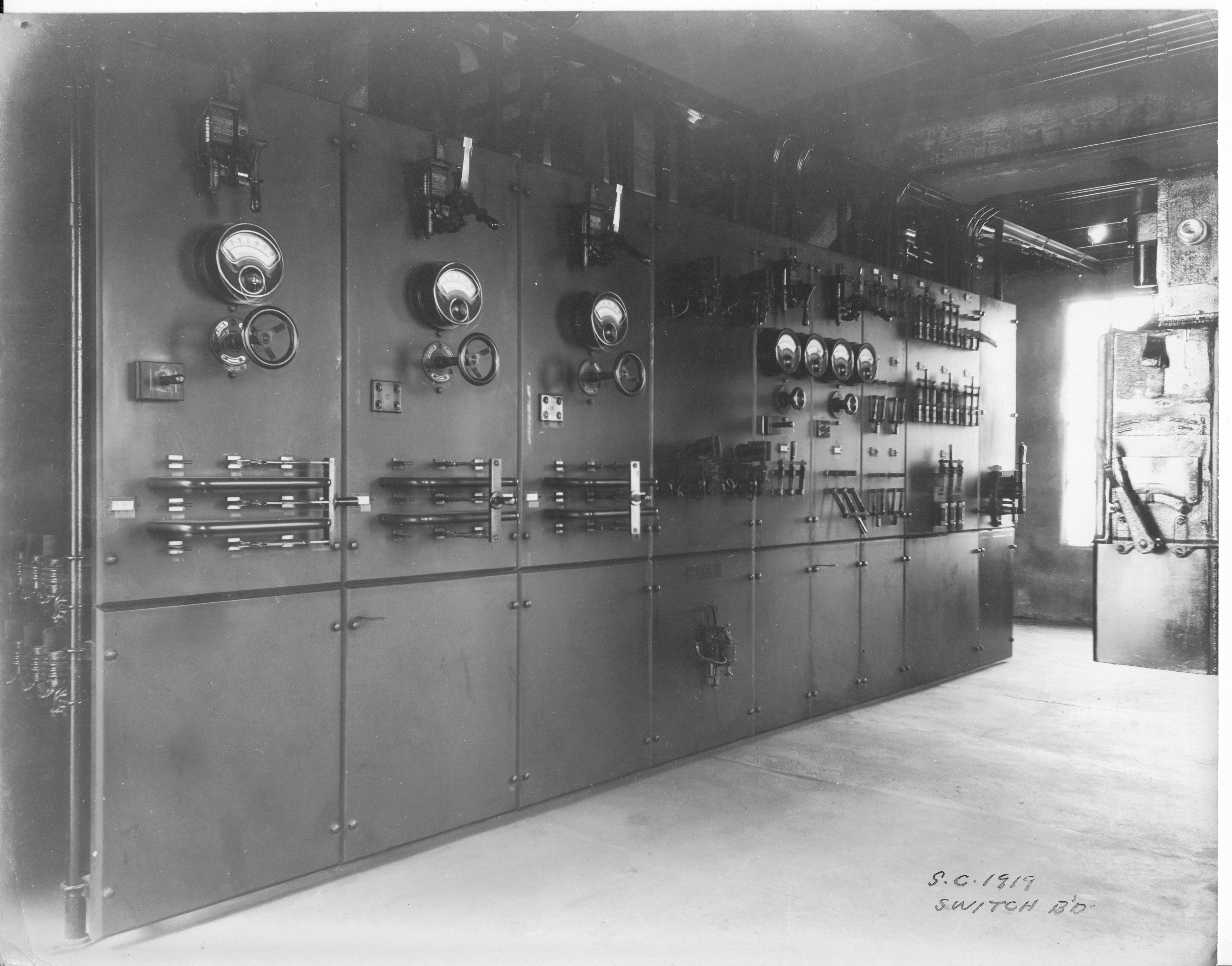
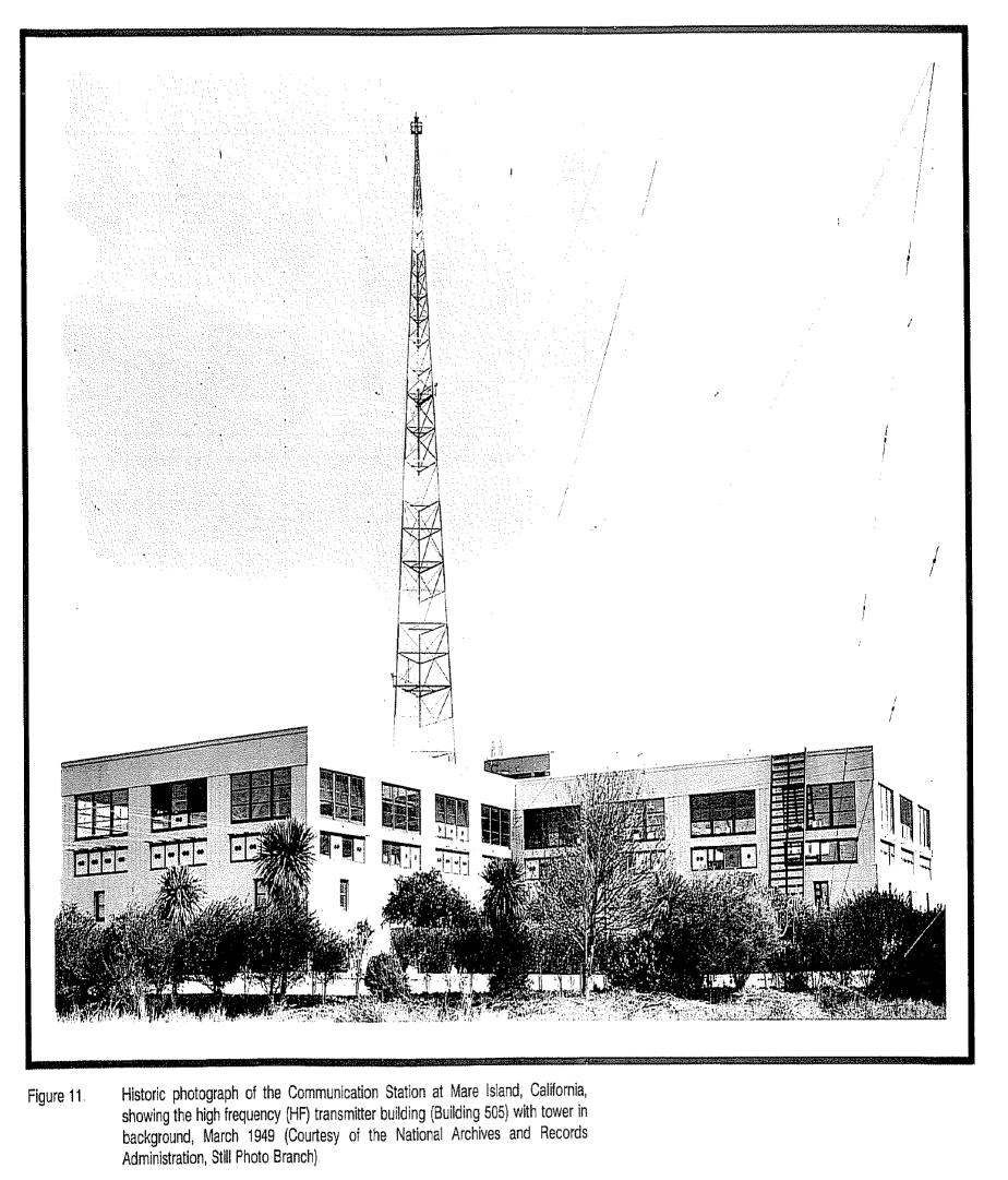
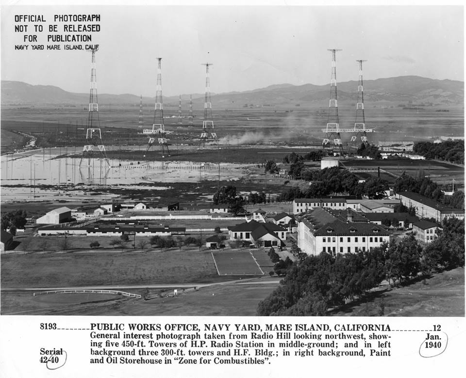
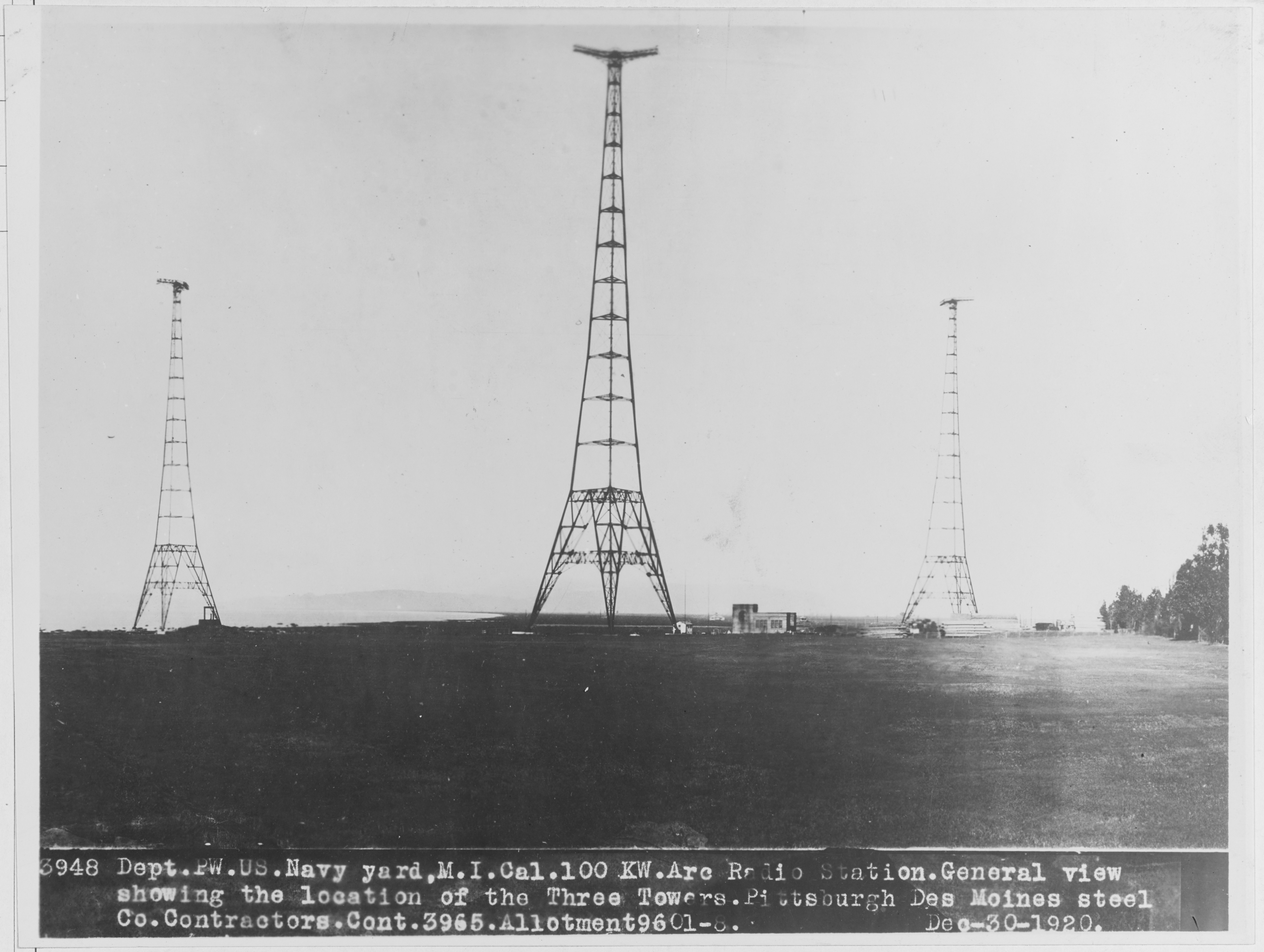
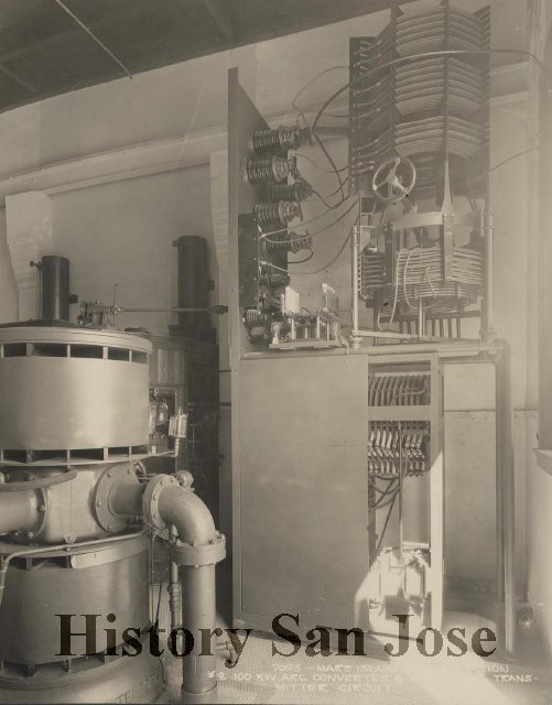
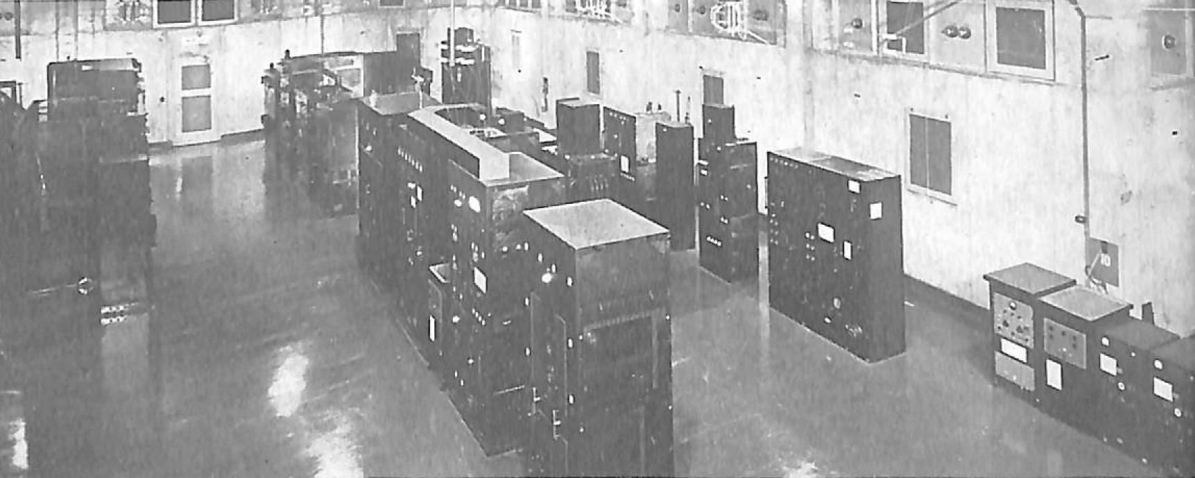
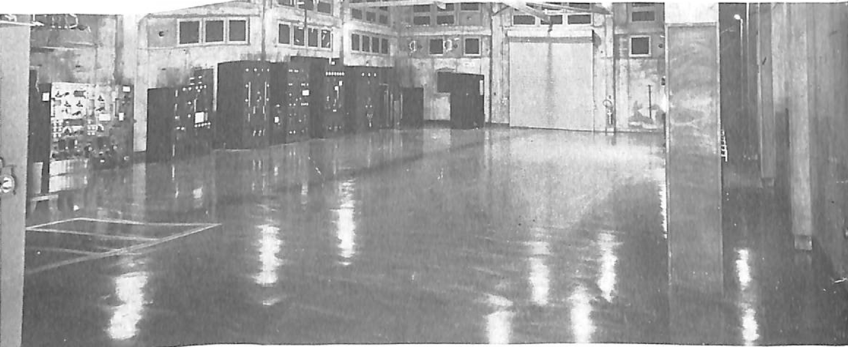
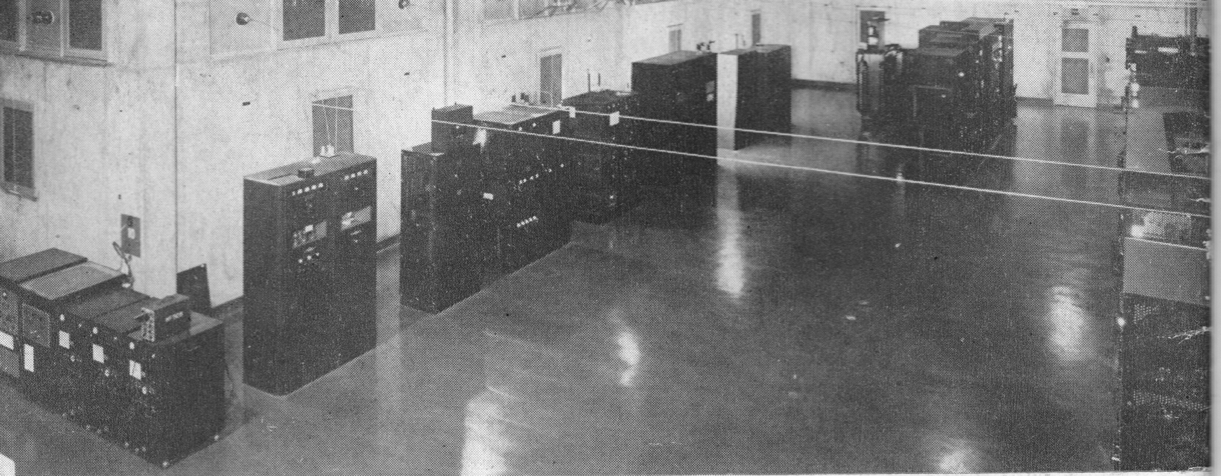
   During WW1, the Navy acquired  Federal Telegraph KSS in South San Francisco. [Photos] It was equipped with one 30 KW and one 40 KW arc transmitters, and operated from Yerba Buena. [Photos] In 1919, the 40 KW arc transmitter was installed at Mare Island (HIPOWER) along with a 100 KW arc transmitter from Tuckerton NJ. An additional 100KW arc transmitter was installed at Mare Island in 1922. [Photos]

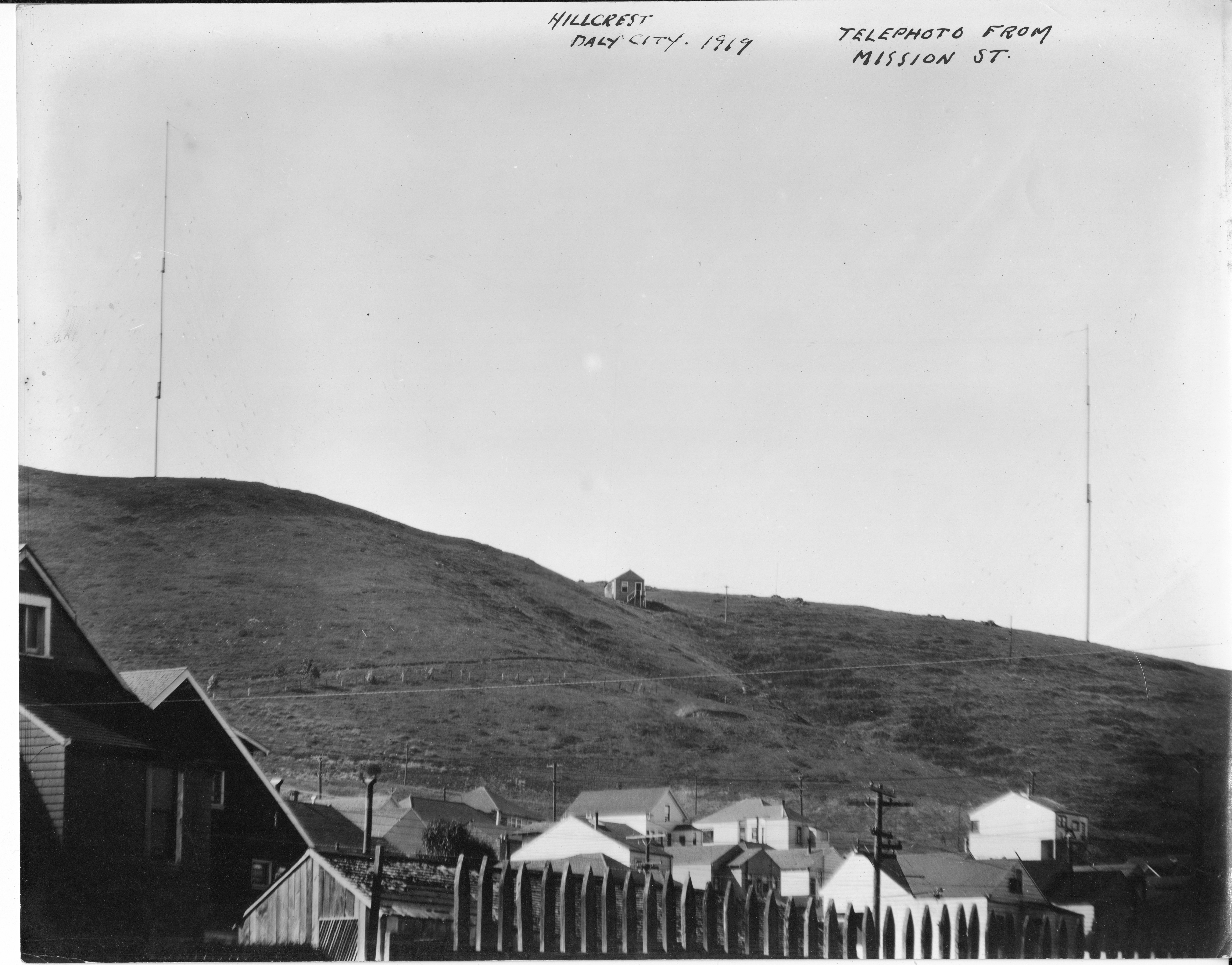
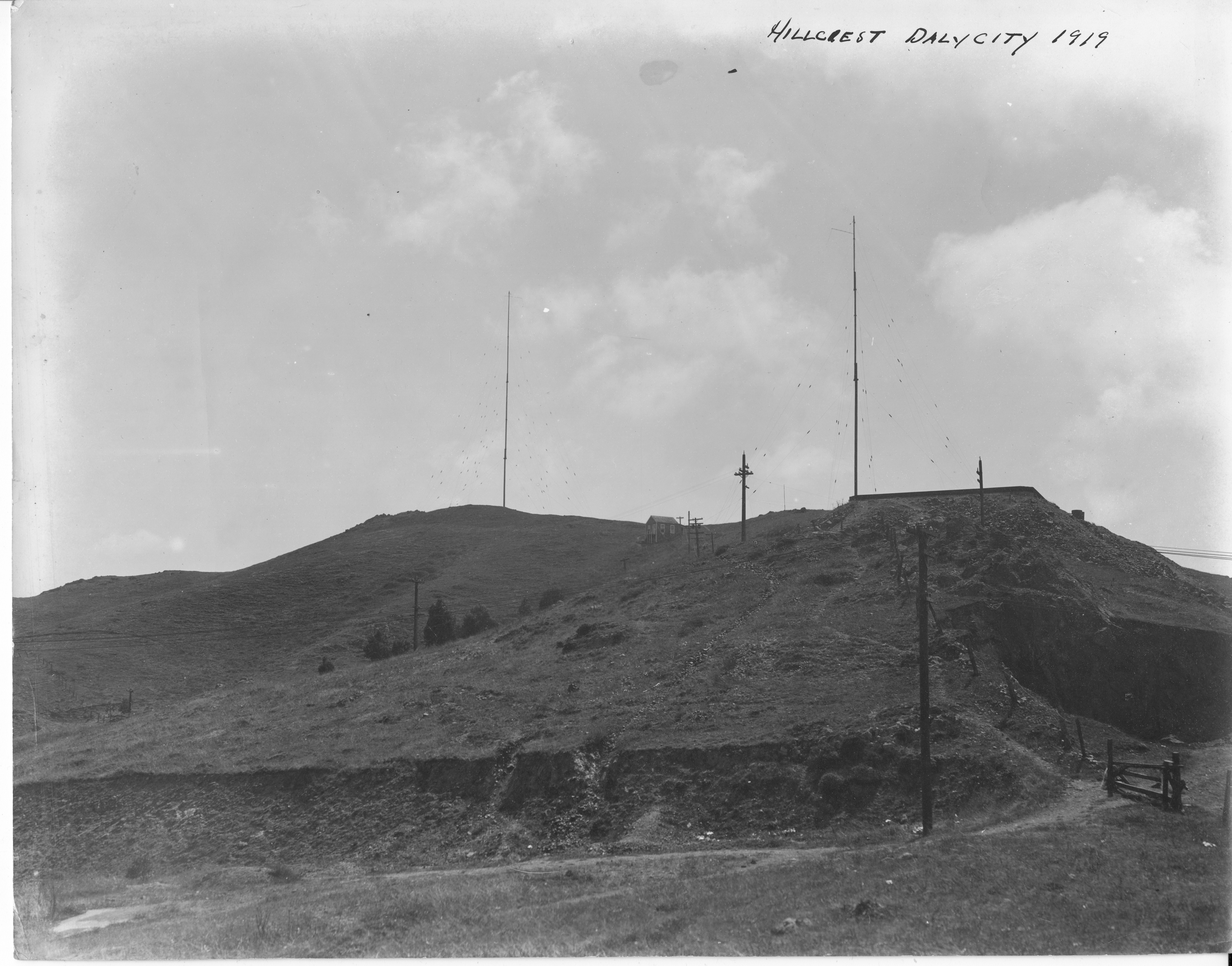
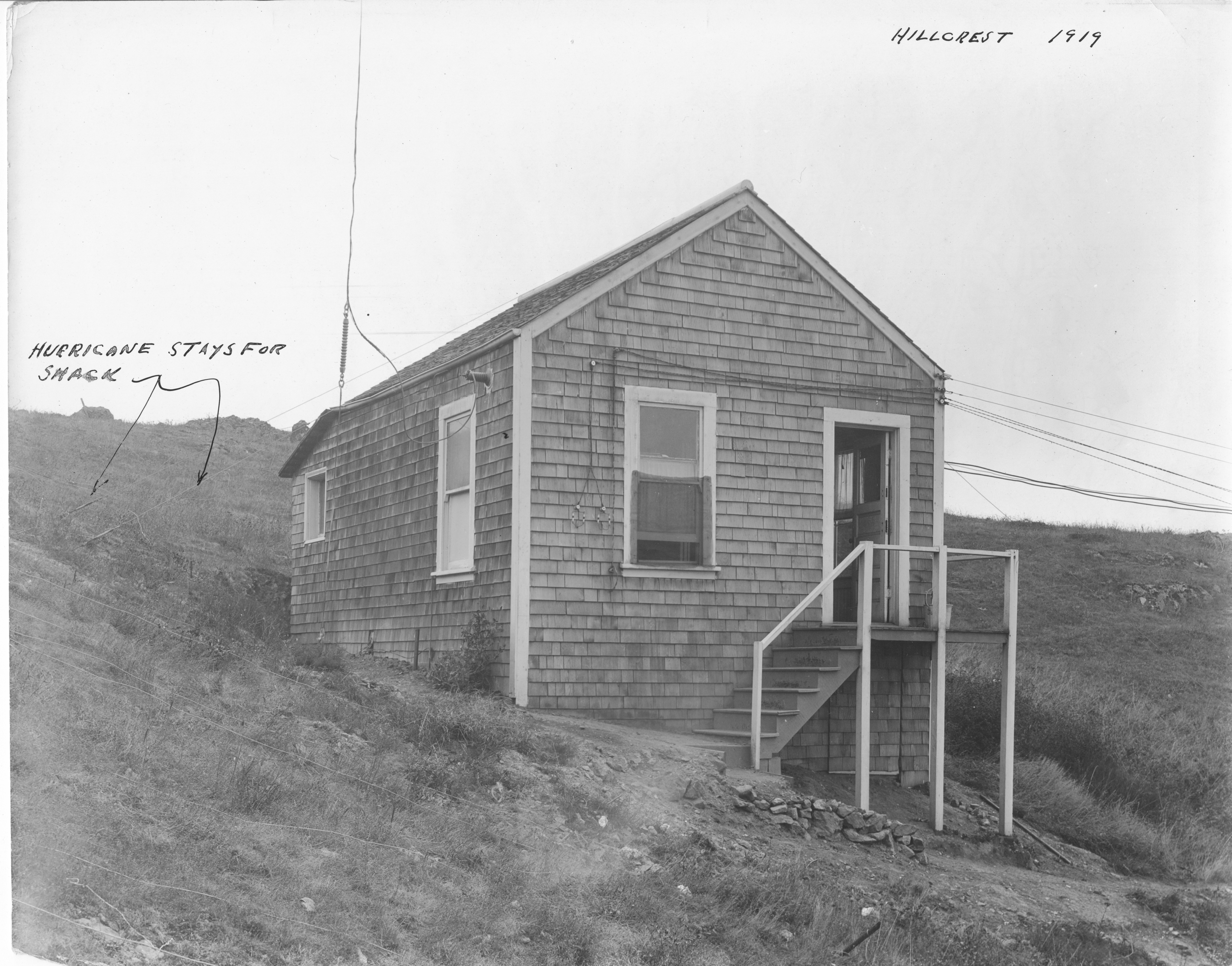
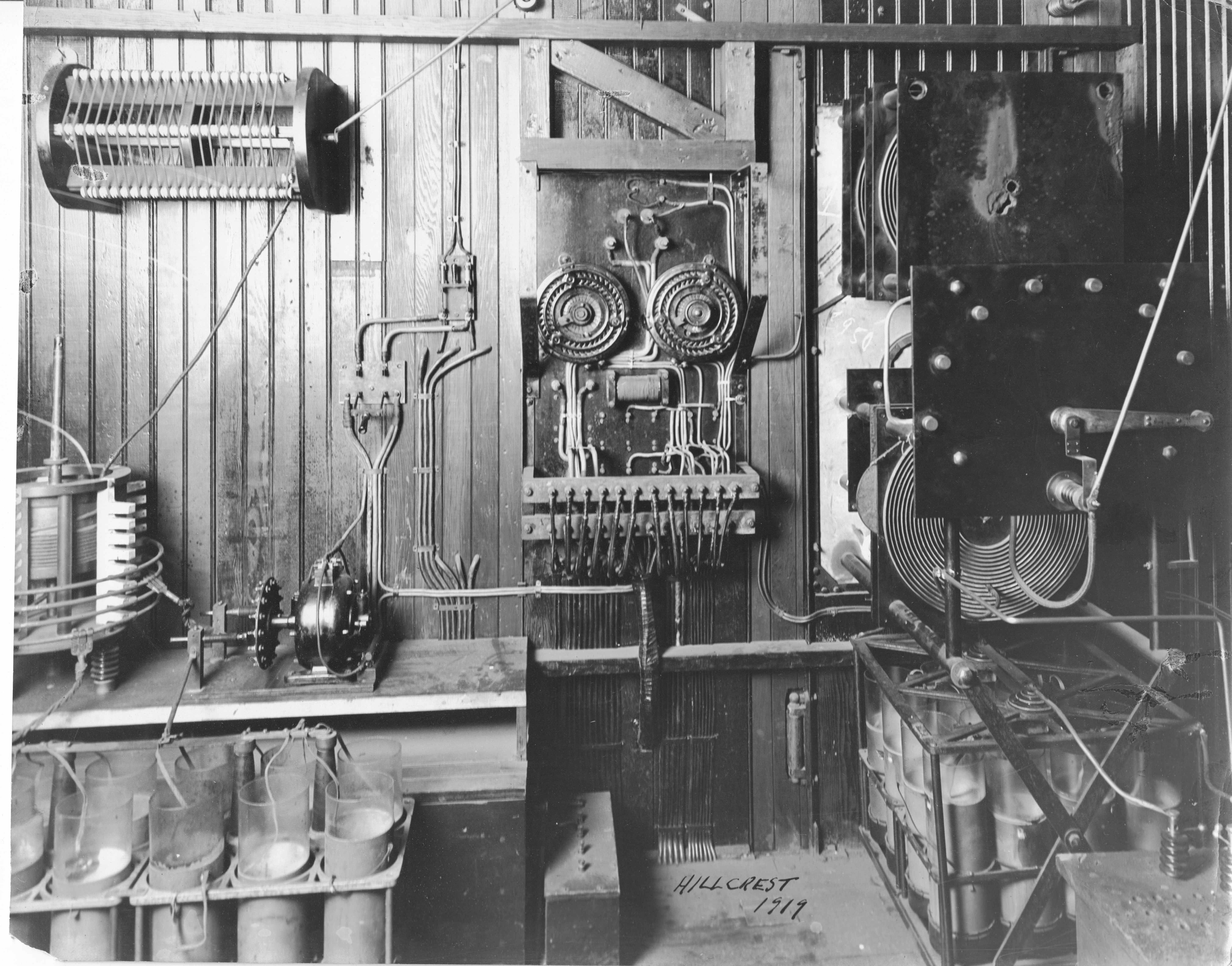
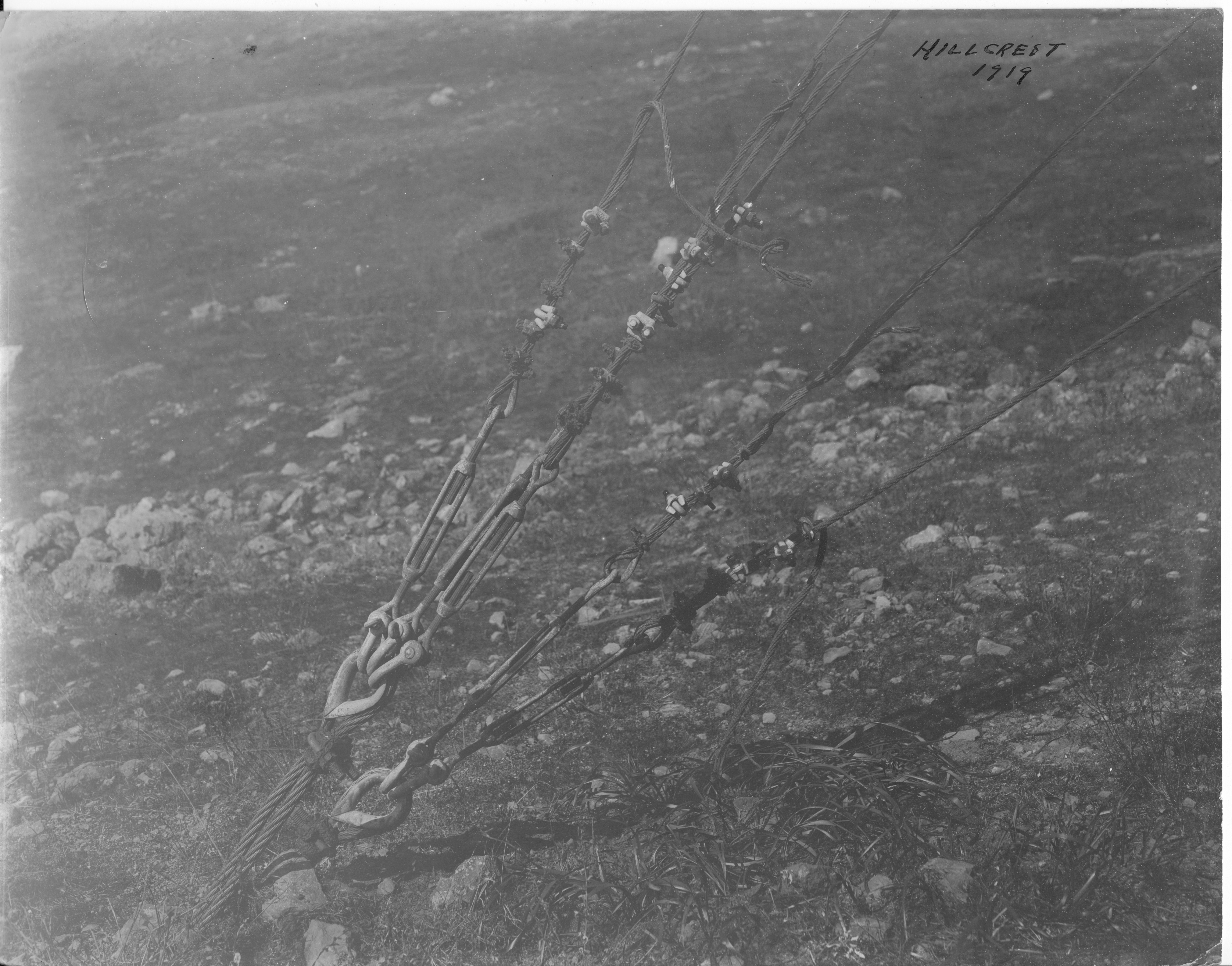
   In April 1917 the Navy also took over the Marconi station KPH at Hillcrest (Daly City). It was equipped with a 5KW quenched gap spark set. [Photos]

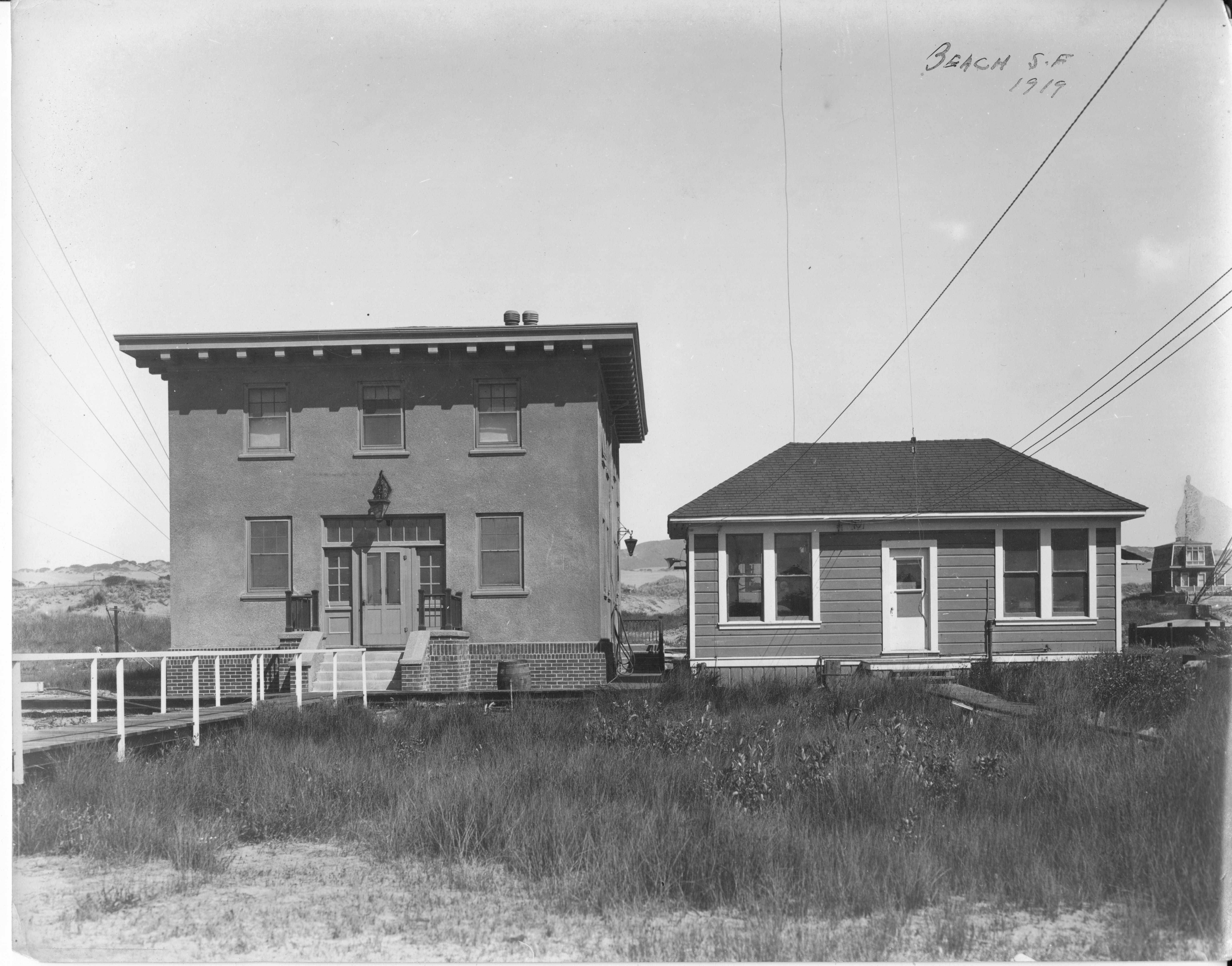
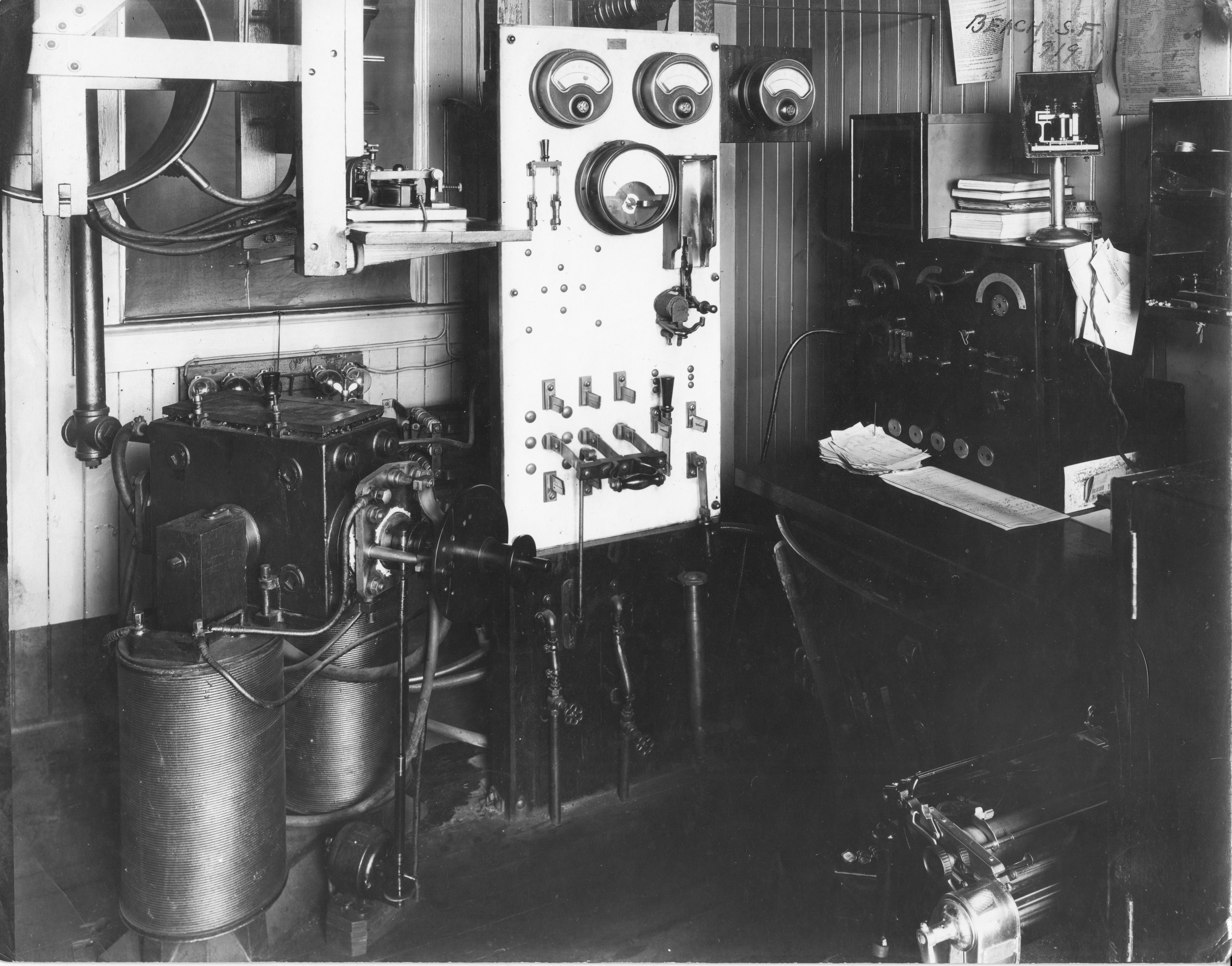
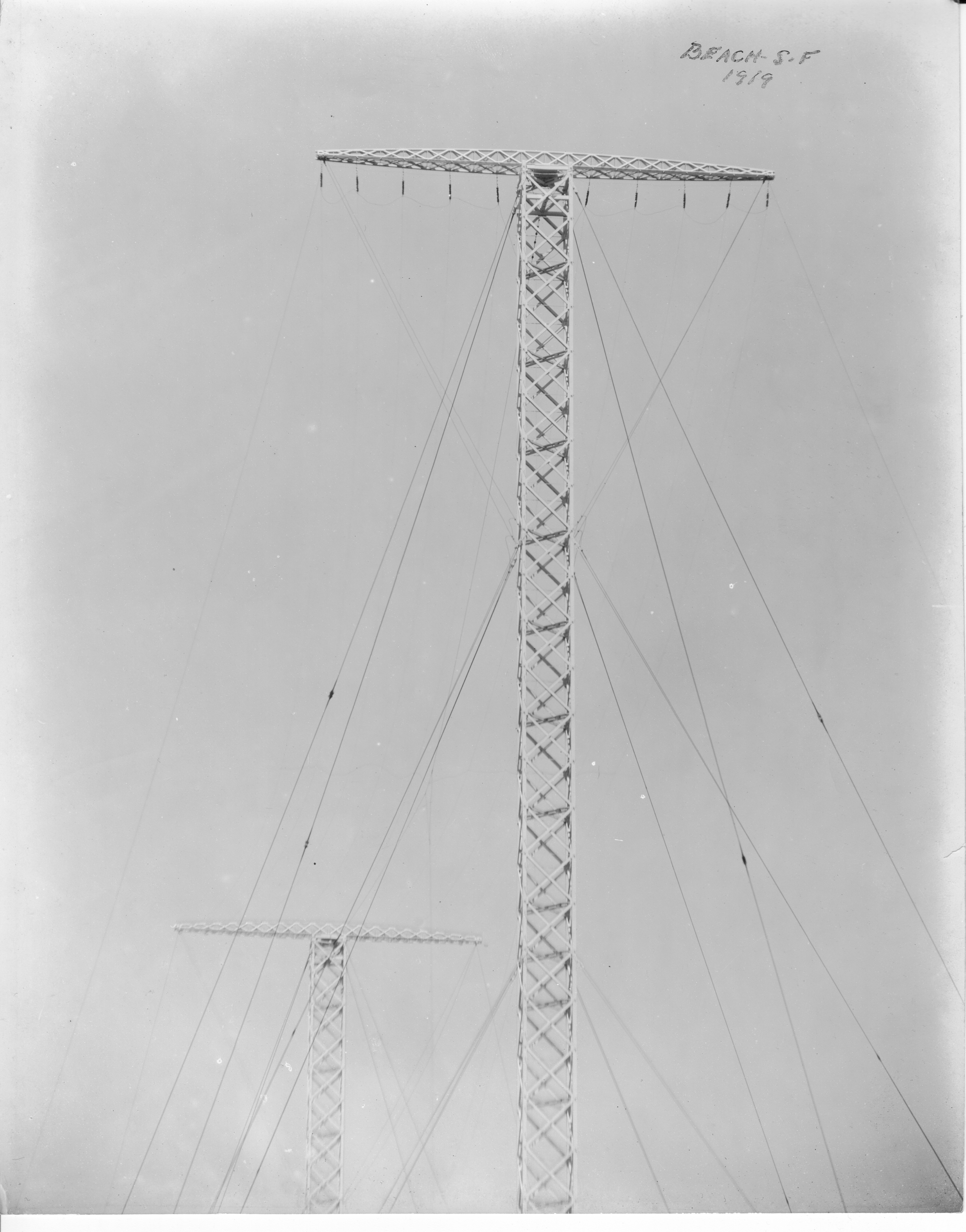
   In addition, the Navy took over the Federal station KFS located on the beach, which had a 12 KW arc transmitter. [Photos]

   After the commercial stations in the San Francisco district were acquired by the Navy, for all purposes of operation and organization, the Yerba Buena, Mare Island, South San Francisco, Beach, and Hillcrest stations were known collectively as the San Francisco Naval Radio Station . The San Francisco station was both the main station of the Pacific Division and the district center station of the San Francisco Communication District .

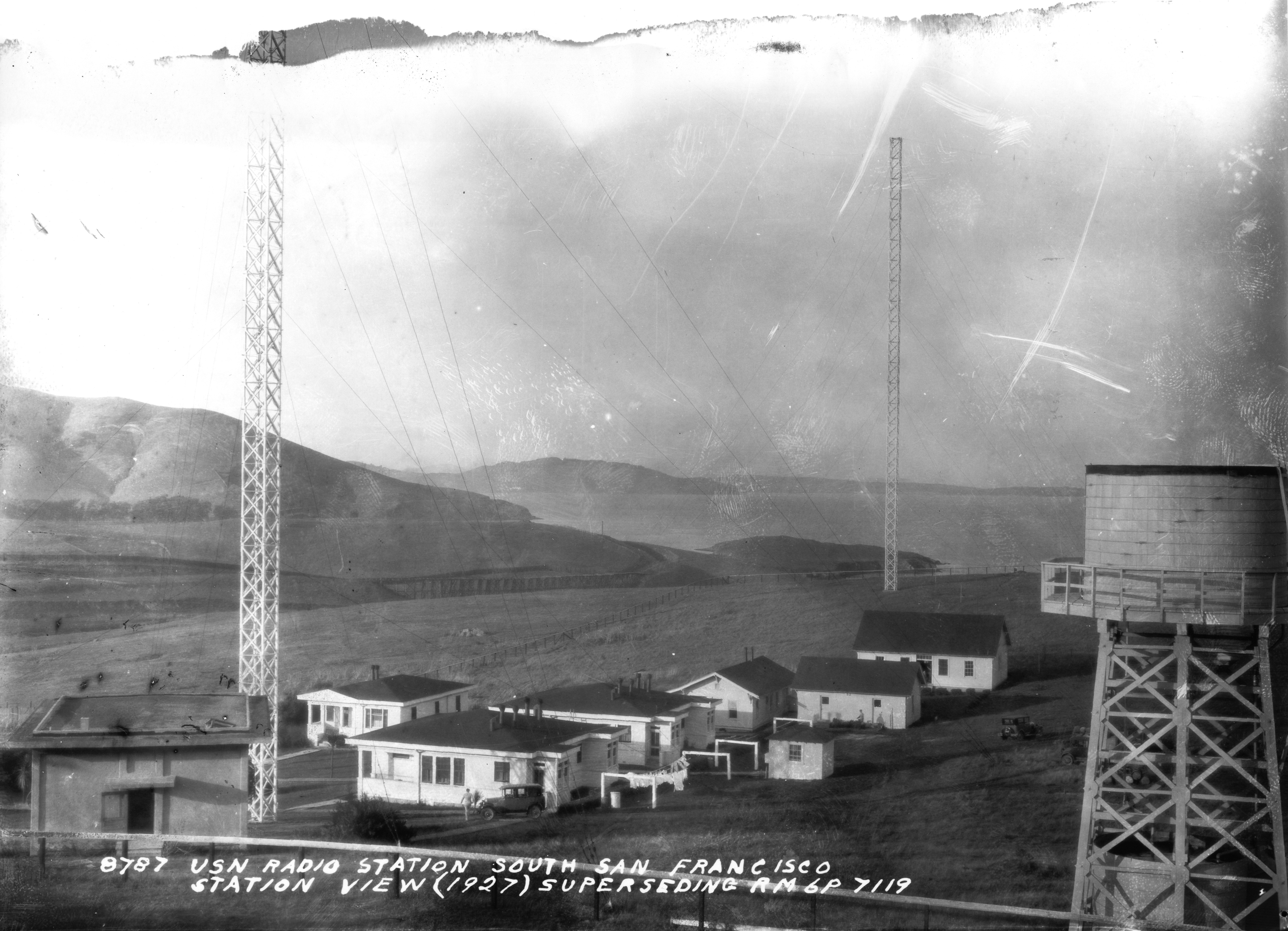
   In May 1923, the Yerba Buena Control Station was moved to the Appraisers Building in San Francisco. At the same time, a new receiver station was established at South San Francisco where signals received from Washington and Honolulu were piped into the control station in the Appraisers Building over lines leased from the Pacific Telephone Co . Signals from San Diego, Puget Sound, the direction finder stations and ships were received directly on receivers installed in the Appraisers Building. 

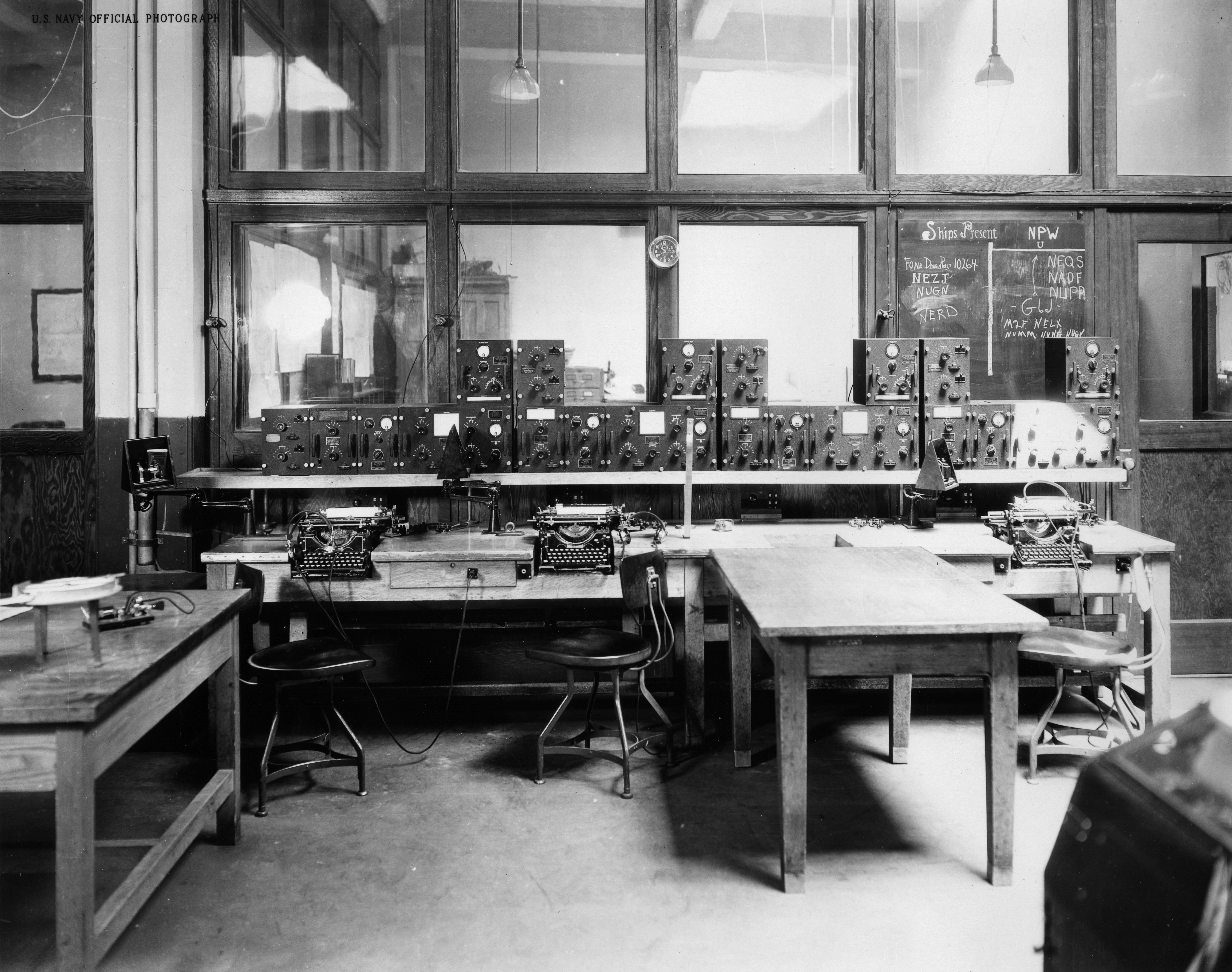
   In 1925 NPG moved to the newly constructed Marine Corps warehouse building in the industrial section of San Francisco, at 100 Harrison St.. Signals from Washington and Honolulu were piped into NPG from the receiver station at South San Francisco. Receivers, and antennas on the roof, were installed in the building for the San Diego, Puget Sound, Direction· Finder Stations, and the ship-shore circuits. Operating positions for duplex operation of the Washington and Honolulu circuits and for the other circuits were located around a large room with desks for the traffic chief, supervisor, and local delivery clerk.

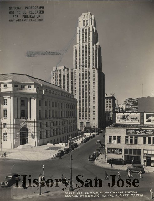
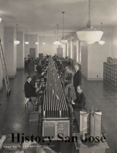
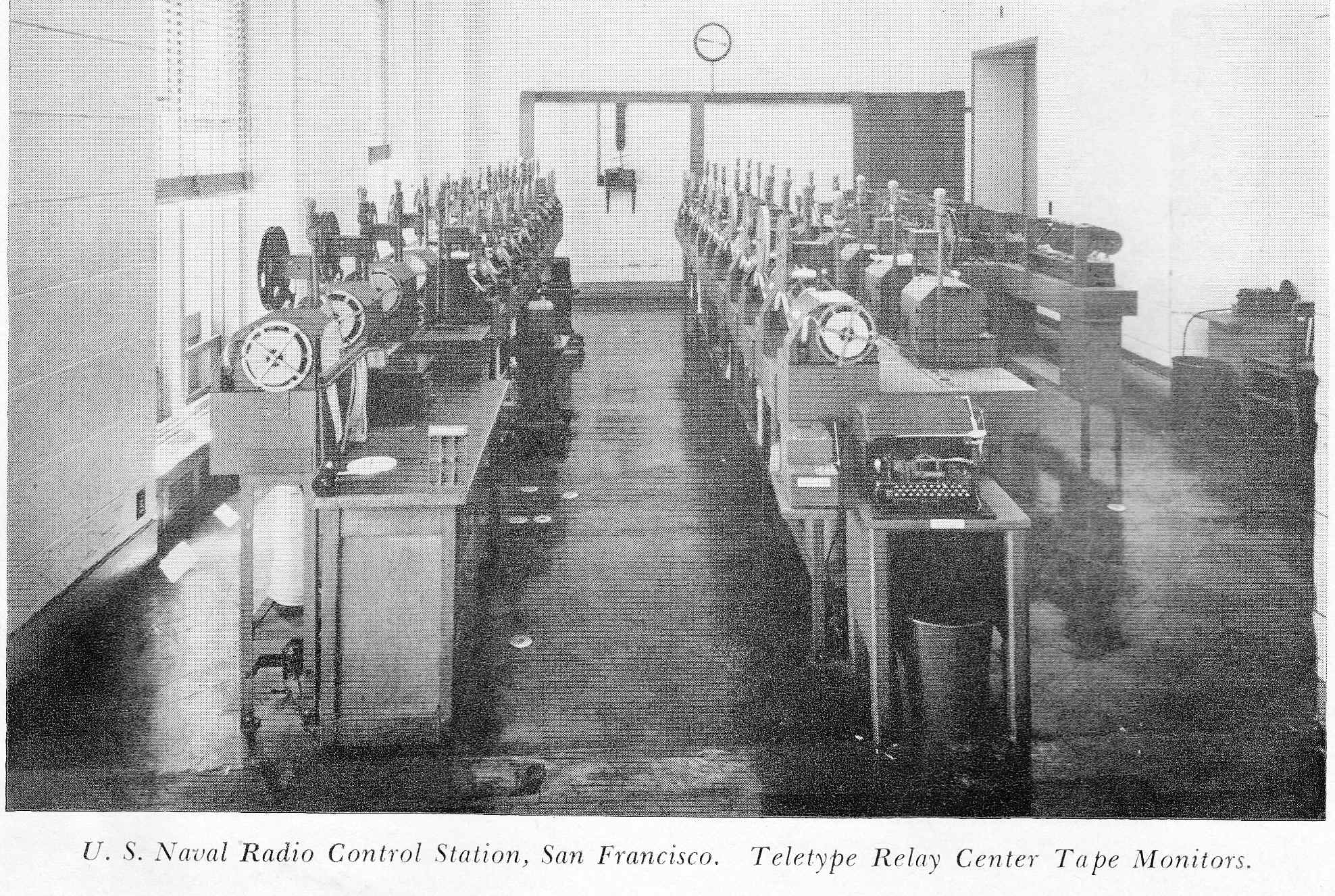
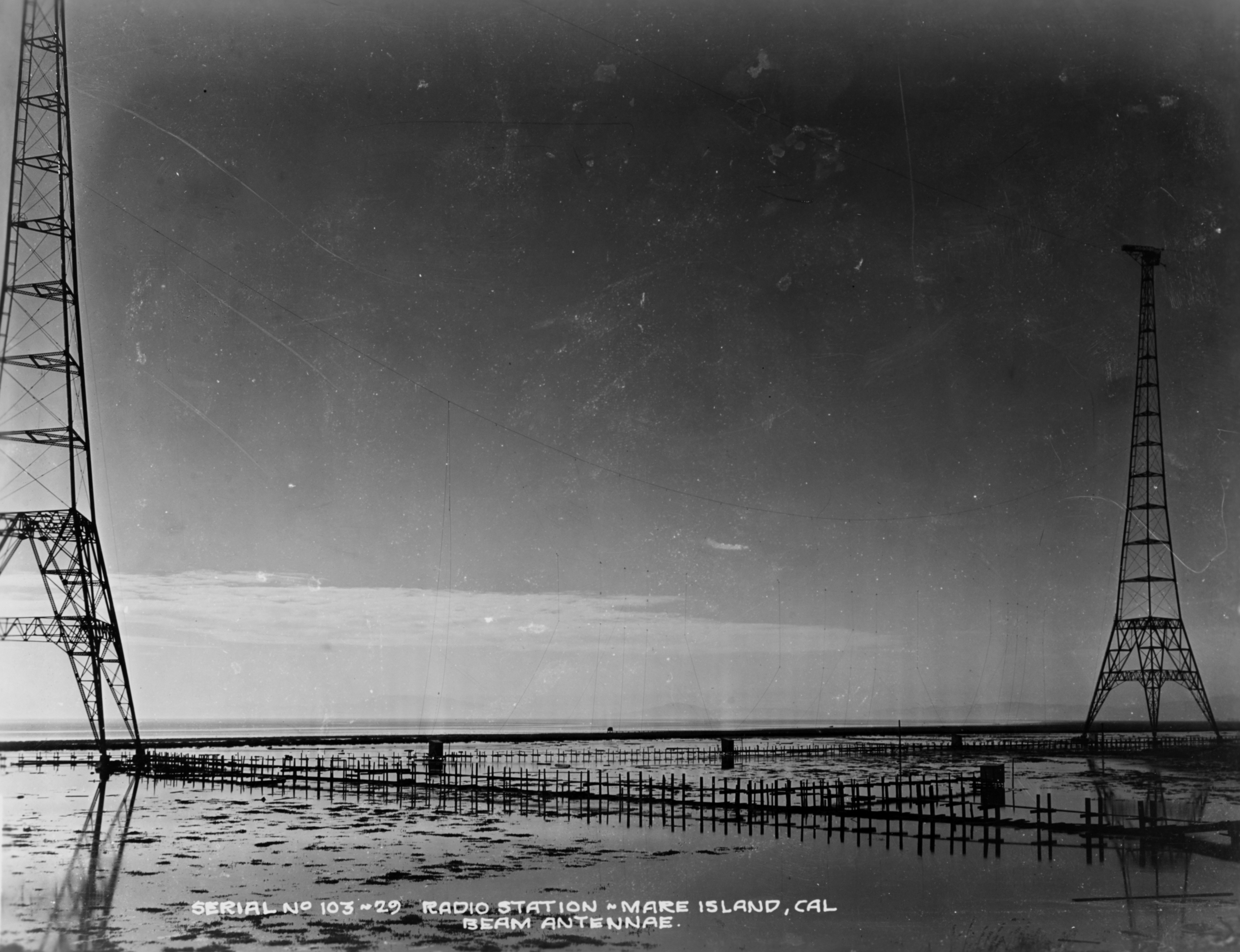
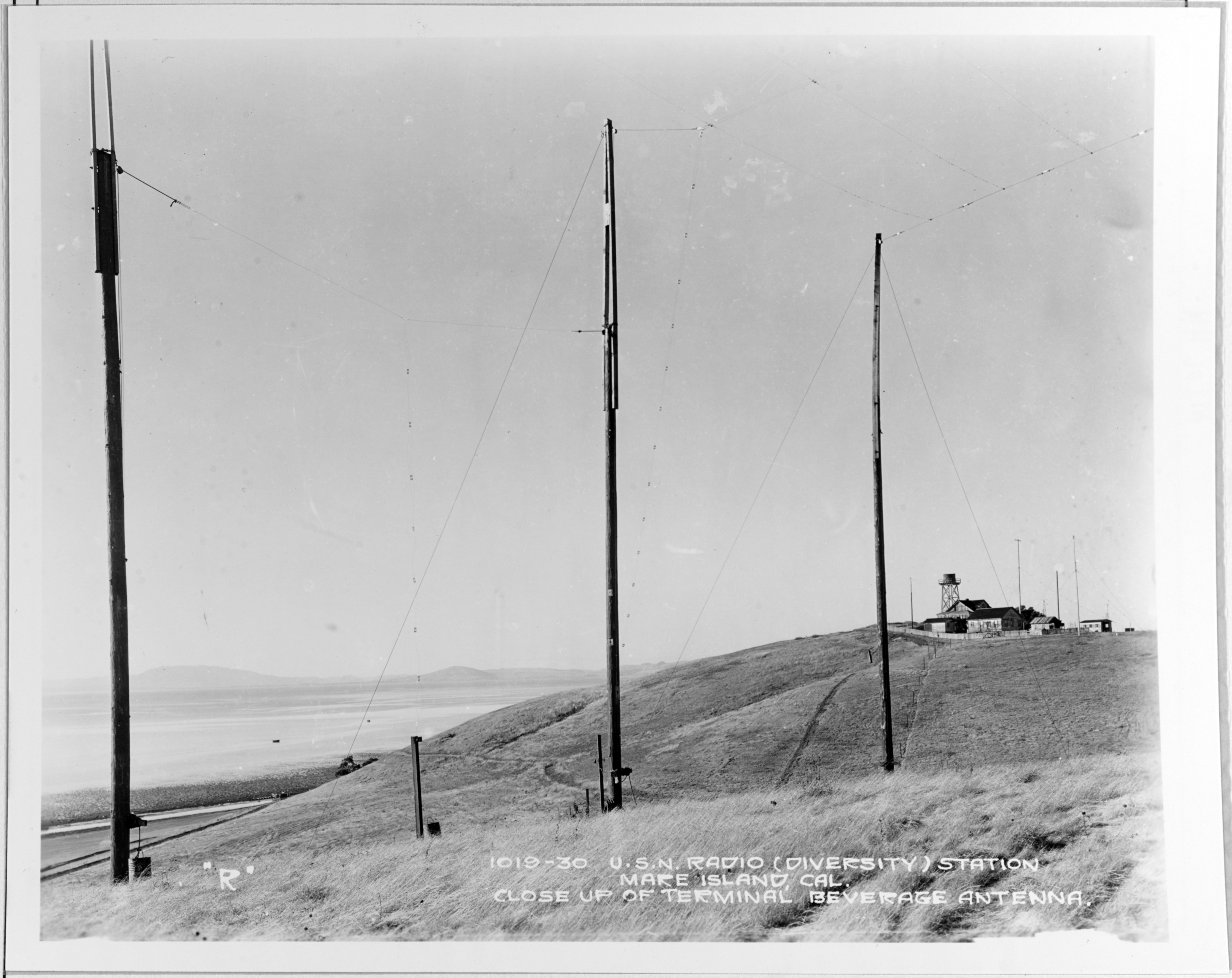
   In 1935, NPG was moved to the newly constructed Federal Office Building in the Civic Center, San Francisco, where it remained for the next twenty-five years . From 1935 until the start of World War II, NPG consisted of the Radio Control Station in the Federal Office Building, the Radio Transmitting Station at Mare Island, the Time and Diversity Receiving Station at Mare Island, the Radio Monitor and Receiving Station at South San Francisco, and several Direction Finder stations. NPG control occupied a few rooms on the third floor of the building, where operating positions were located along a conveyor belt which carried messages between the operators and the supervisor and. traffic chief. High speed Kleinschmidt and Boehme tape equipments were used on the primary circuits to Washington and Honolulu. A few receivers were installed for the San Diego-Puget Sound circuit, the DF stations, and the ship-shore circuits. Photos

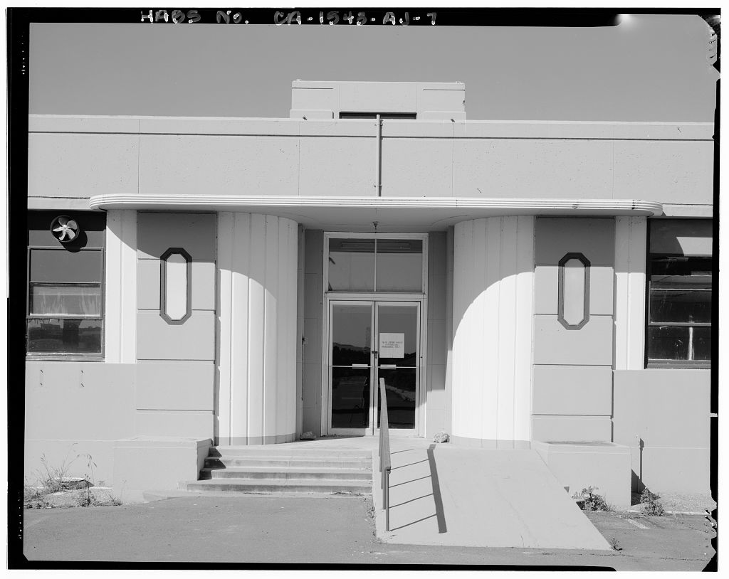
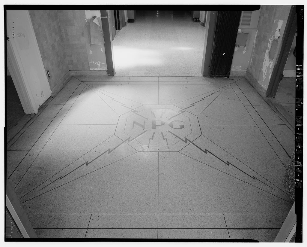
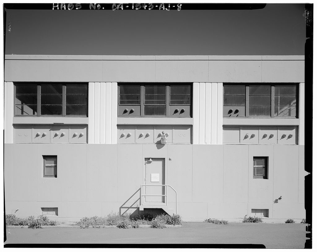
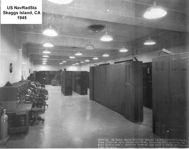
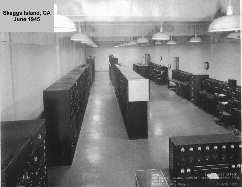
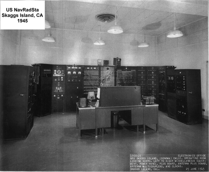
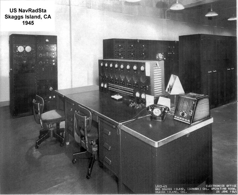
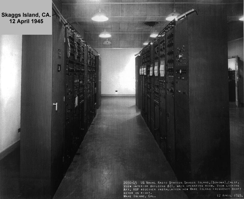
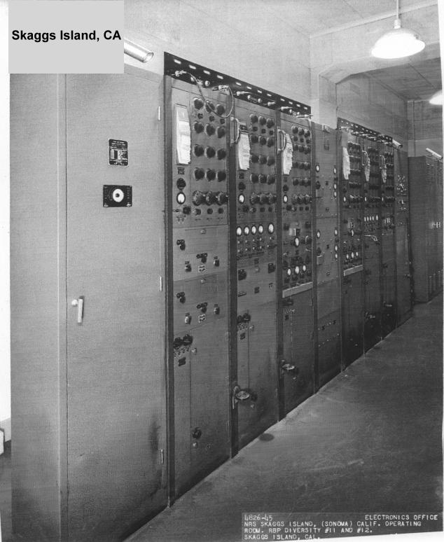
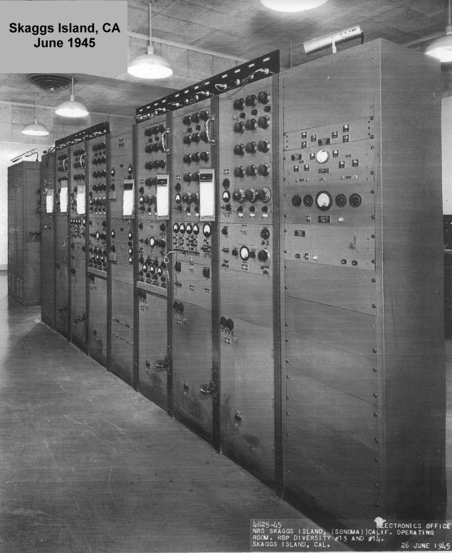
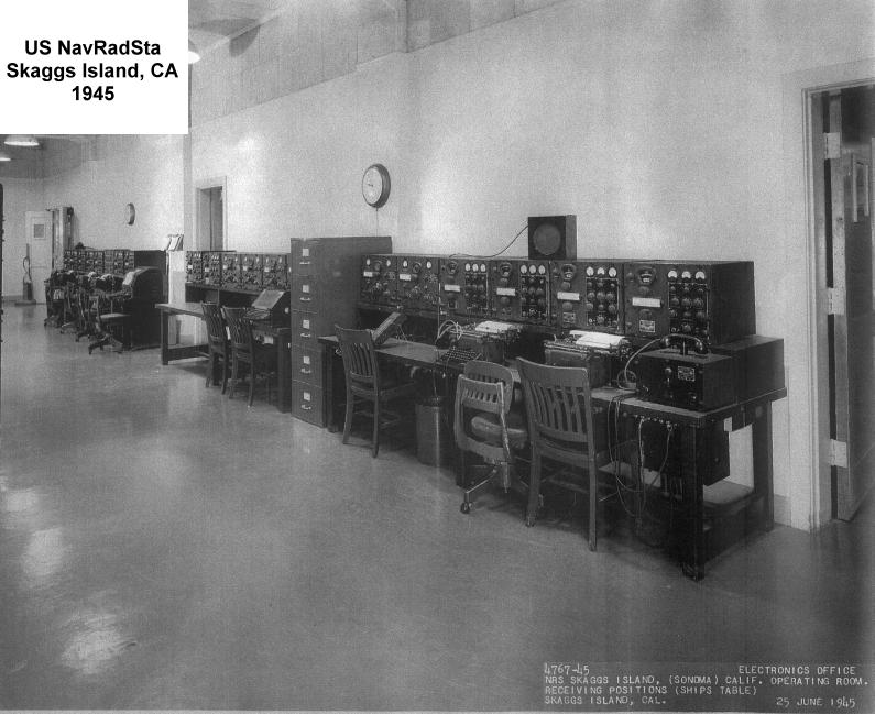
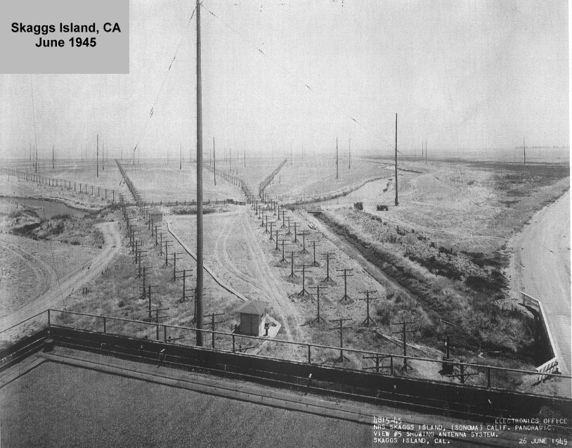
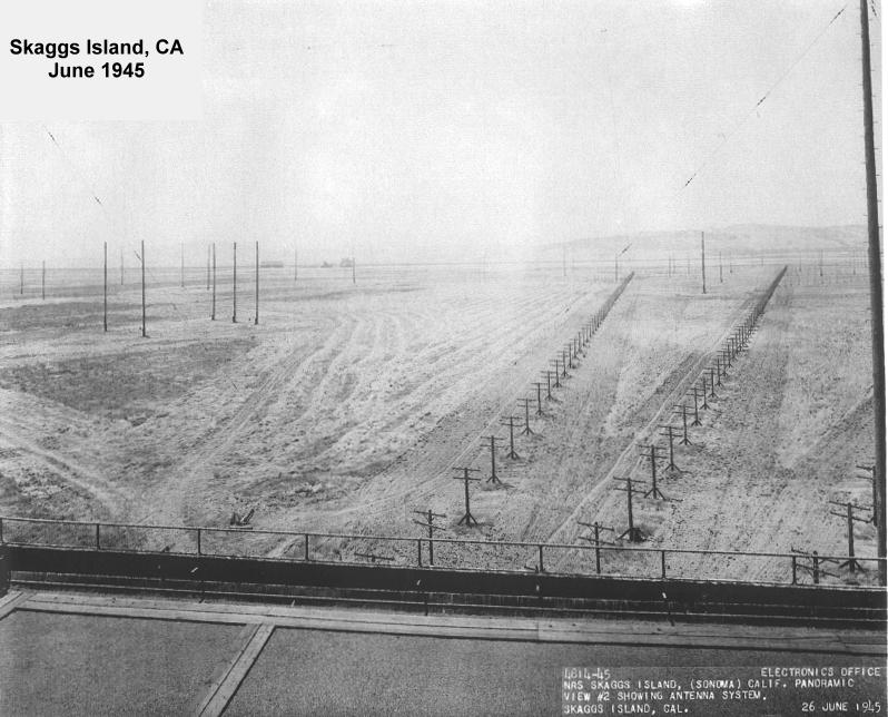
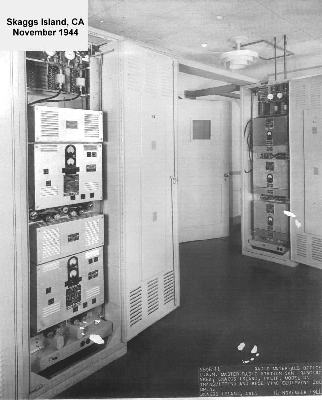
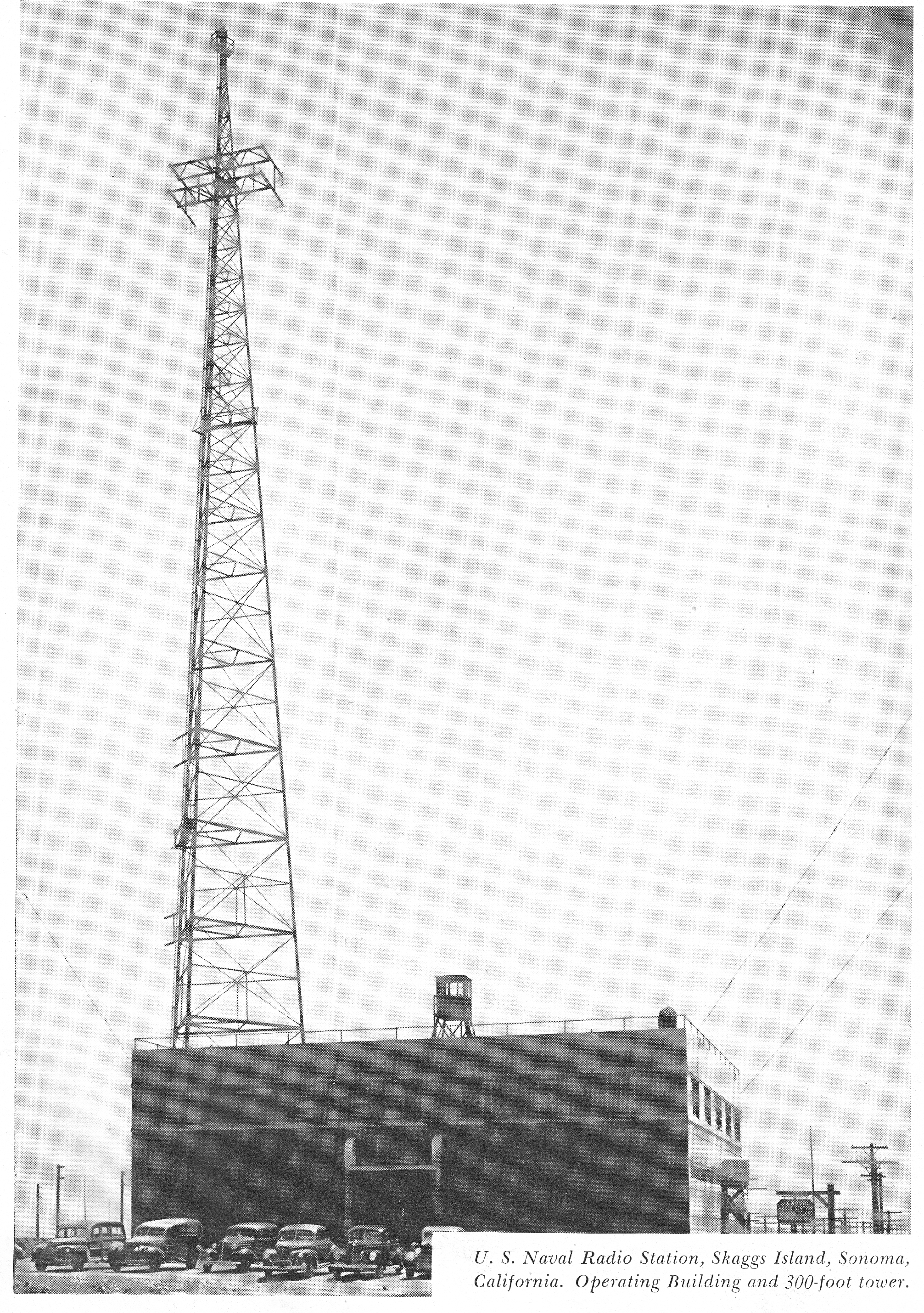
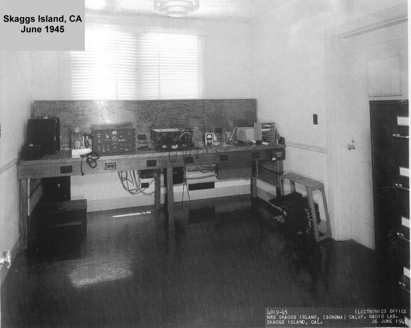
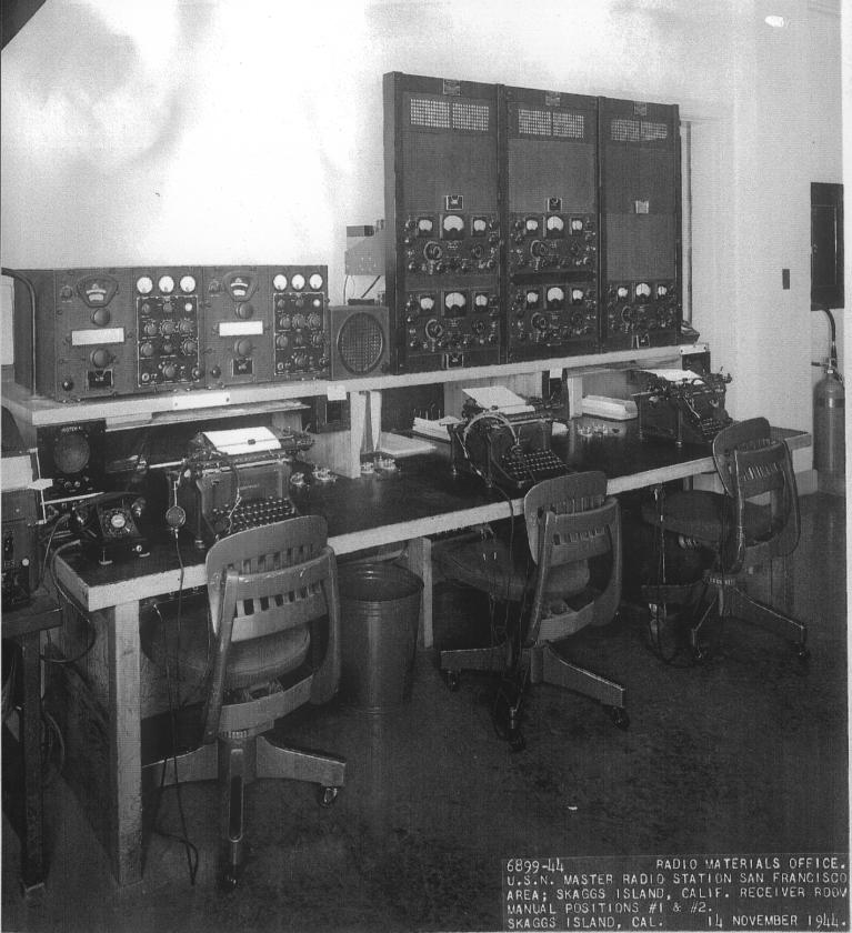
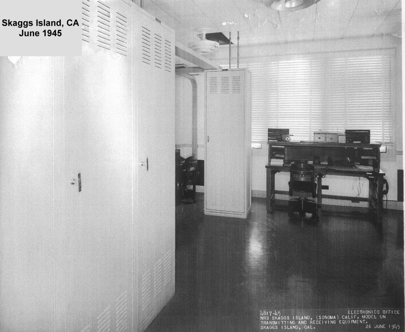
   With the increase of communication circuits and the requirement for a better, noise-free location, the Radio Receiving site at Skaggs Island was developed and construction started in 1938 . Naval Radio Station (R). Skaggs Island, on the northern edge of San Francisco Bay, became a component part of NPG in 1942 as replacement for the old South San Francisco receiving station. [1945 Photos] All of Mare Island's radio receiving functions were also shifted to the new station in 1942. Initial use of' the 3300 acre site was to provide receiving facilities for point to point, ship shore, local harbor, and inter and intra-district nets as the occasion demanded. Supplementary Radio (later NAVSECGRU) activities were added at Skaggs Island [more photos and info]

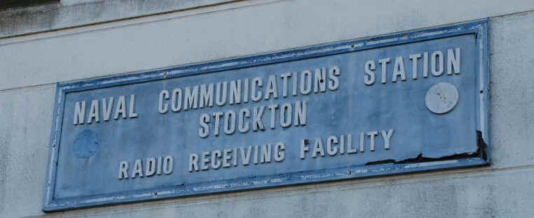
   In 1962, NAVCOMMSTA San Francisco moved to Stockton (Rough and Ready Island).  [1970's Stockton Photos]

   In 1965, Transmitter operations were moved from Mare Island to NAVRADSTA (T) Dixon  [info, photos]


1936 - Radio Control - Fed Office Bldg
sanfrancisco-fed-bldg-1936-01.jpg (70331 bytes)
1936 - Radio Control - Fed Office Bldg
sanfrancisco-fed-bldg-1936-02.jpg (52576 bytes)
Ships Table, Marine Receiving, in the Control Station at the Twelfth Naval District Radio Headquarters 1927
sanfran-control-099.01.jpg (4708420 bytes)

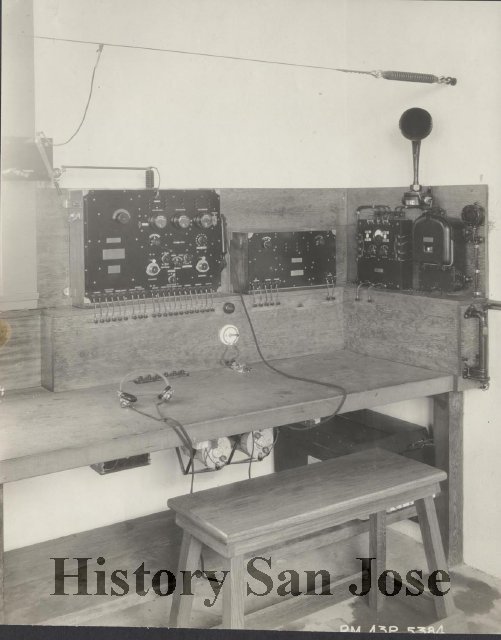
Another view of Marine Receiving Table

Teletype Relay San Francisco 1945
sanfran-relay-1945.jpg (1149228 bytes)

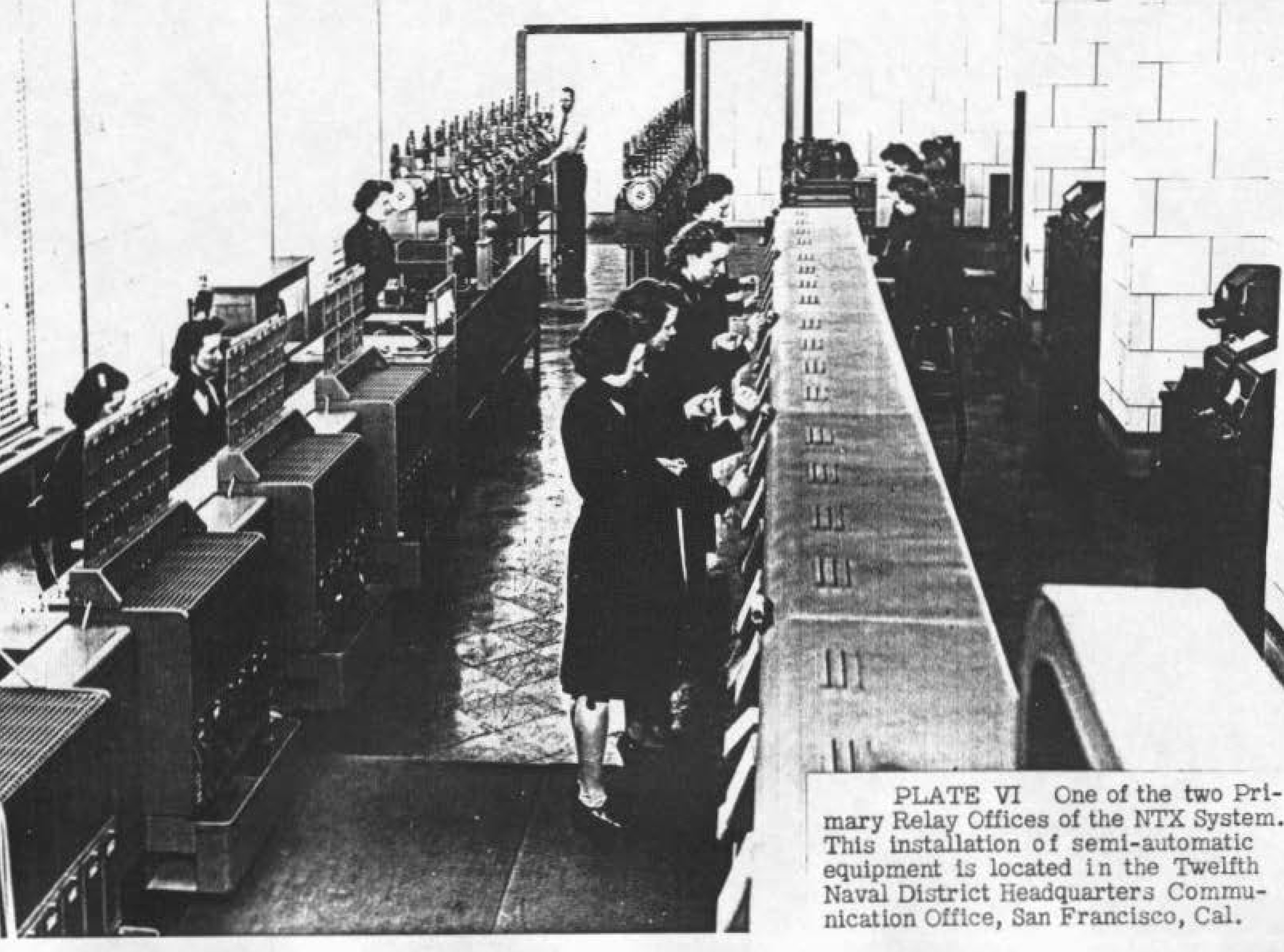
Teletype Relay San Francisco 1948
sanfrancisco-1948.jpg (667802 bytes)

US Naval Radio Station Yerba Buena - NPG

More interior photos - More exterior photos
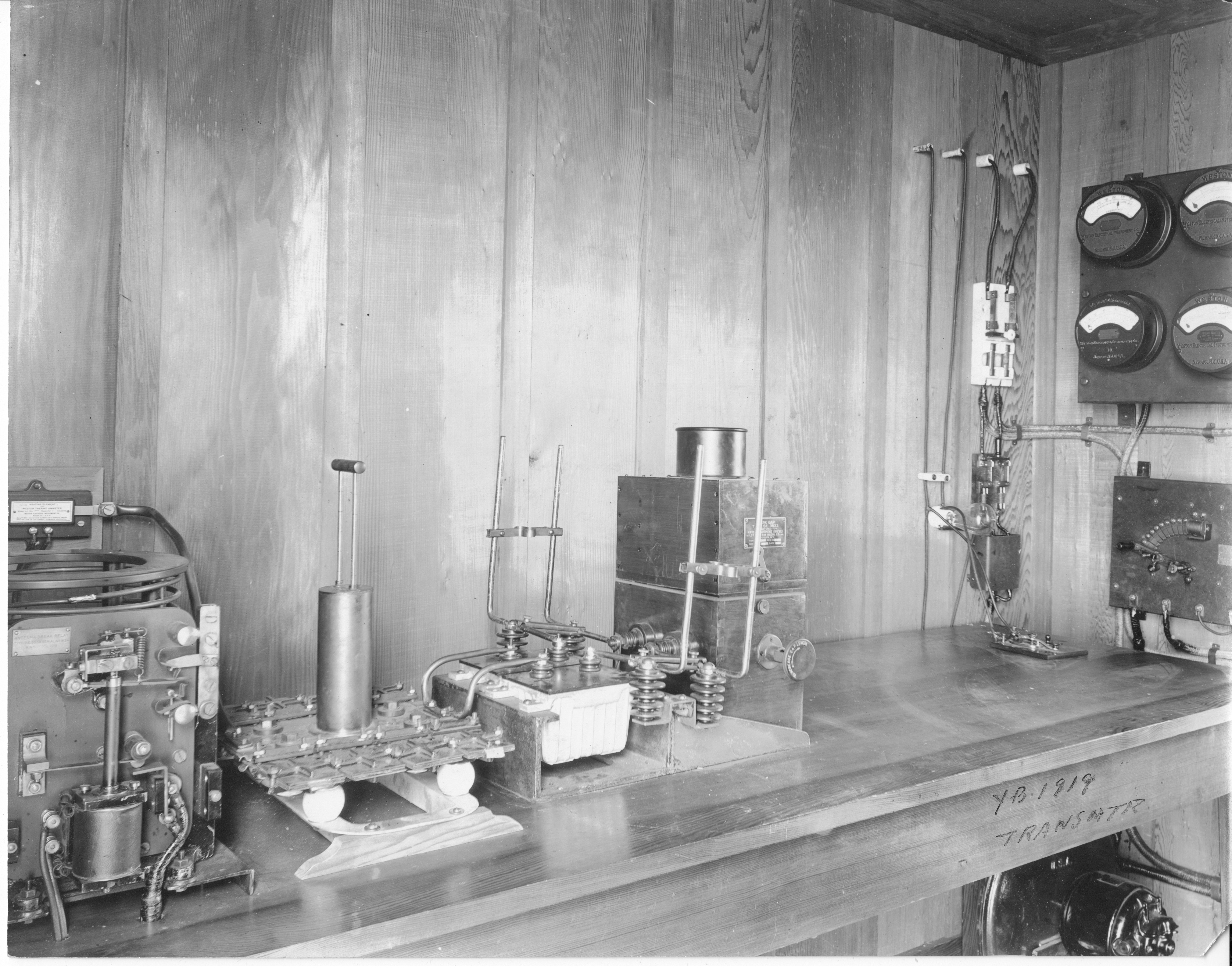
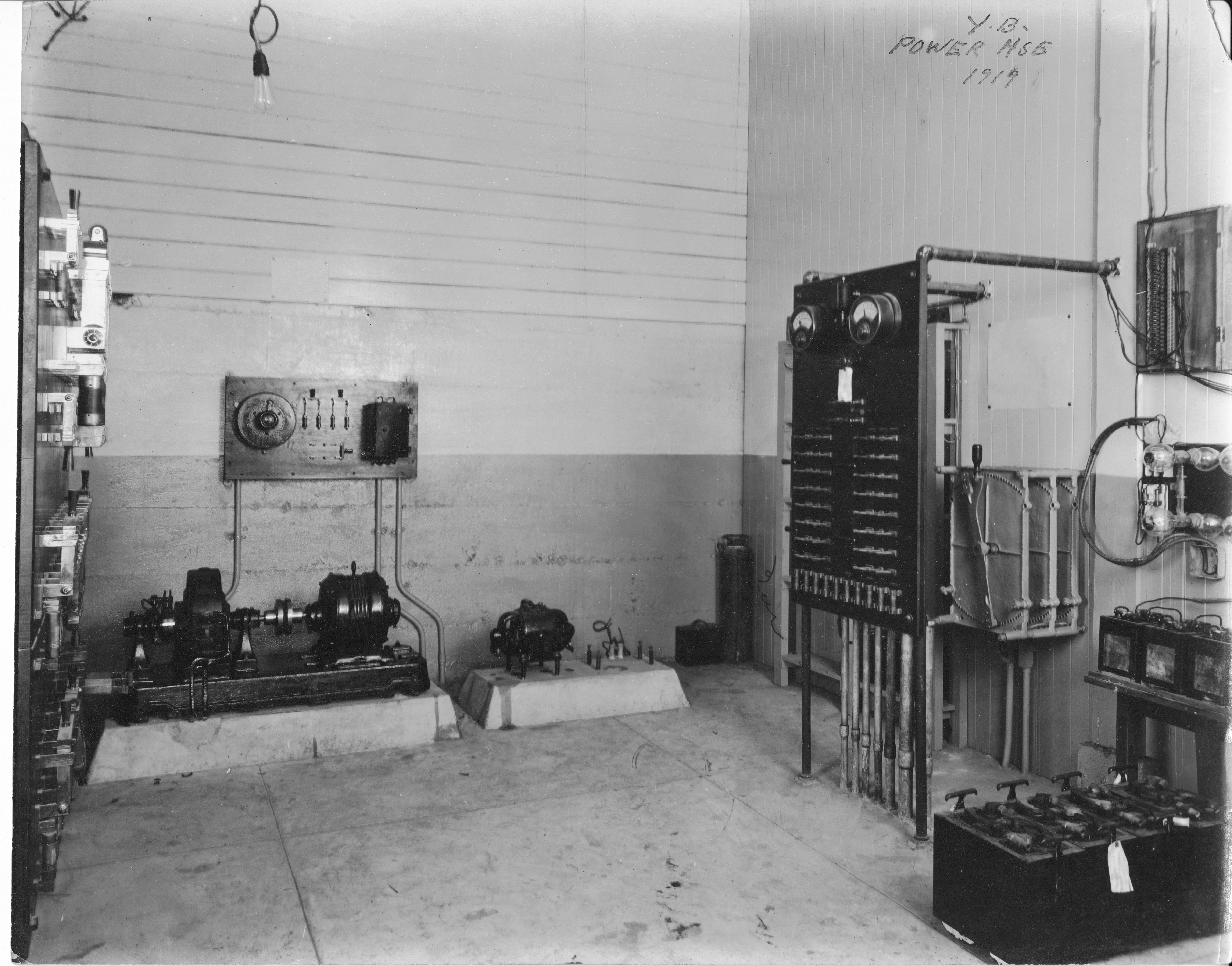
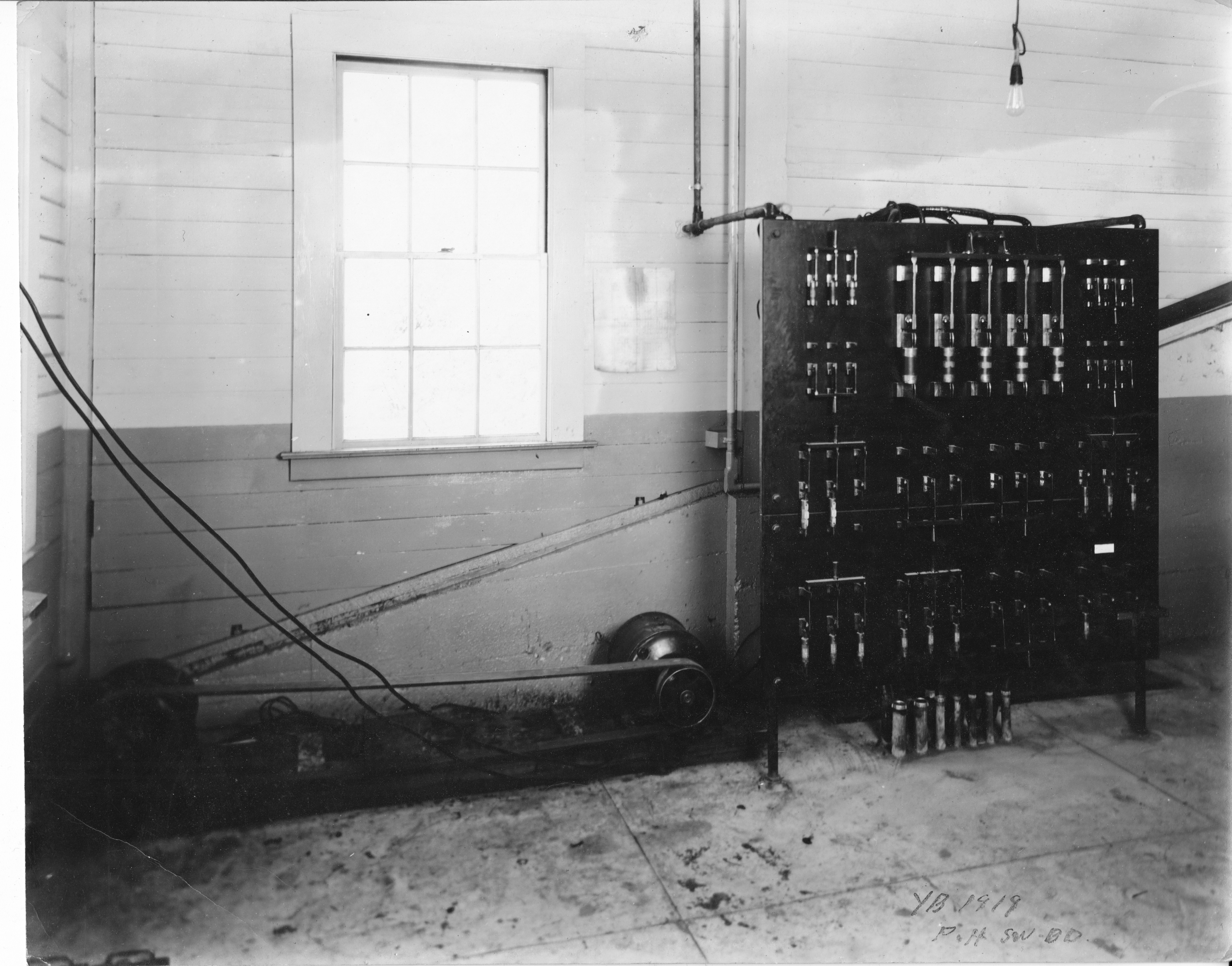
1917
yerba-buena-1917-01.jpg (57766 bytes)

- 1919 photos thanks to Gloria Conley
Yerba Buena 1919
yerba-1919-07.jpg (3379900 bytes)
Yerba Buena 1919
yerba-1919-06.jpg (4005693 bytes)
Yerba Buena 1919 - Barrage Loop Antennas
yerba-1919-08.jpg (4753316 bytes)
Yuerba Buena 1919 - Shortwave Operating Booth
yuerba-buena-097-B.06.jpg (2648738 bytes)
Yerba Buena 1919
yerba-1919-05.jpg (2818267 bytes)
Yerba Buena 1921
yerba-100368.jpg (520094 bytes)
Yerba Buena 1921
goat-island-100367.jpg (785921 bytes)
Yerba Buena 1919
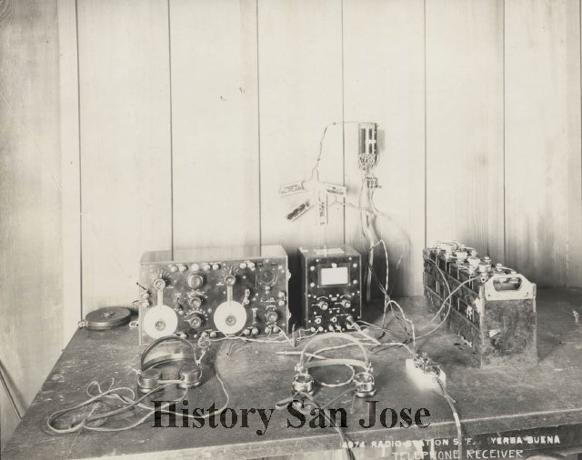
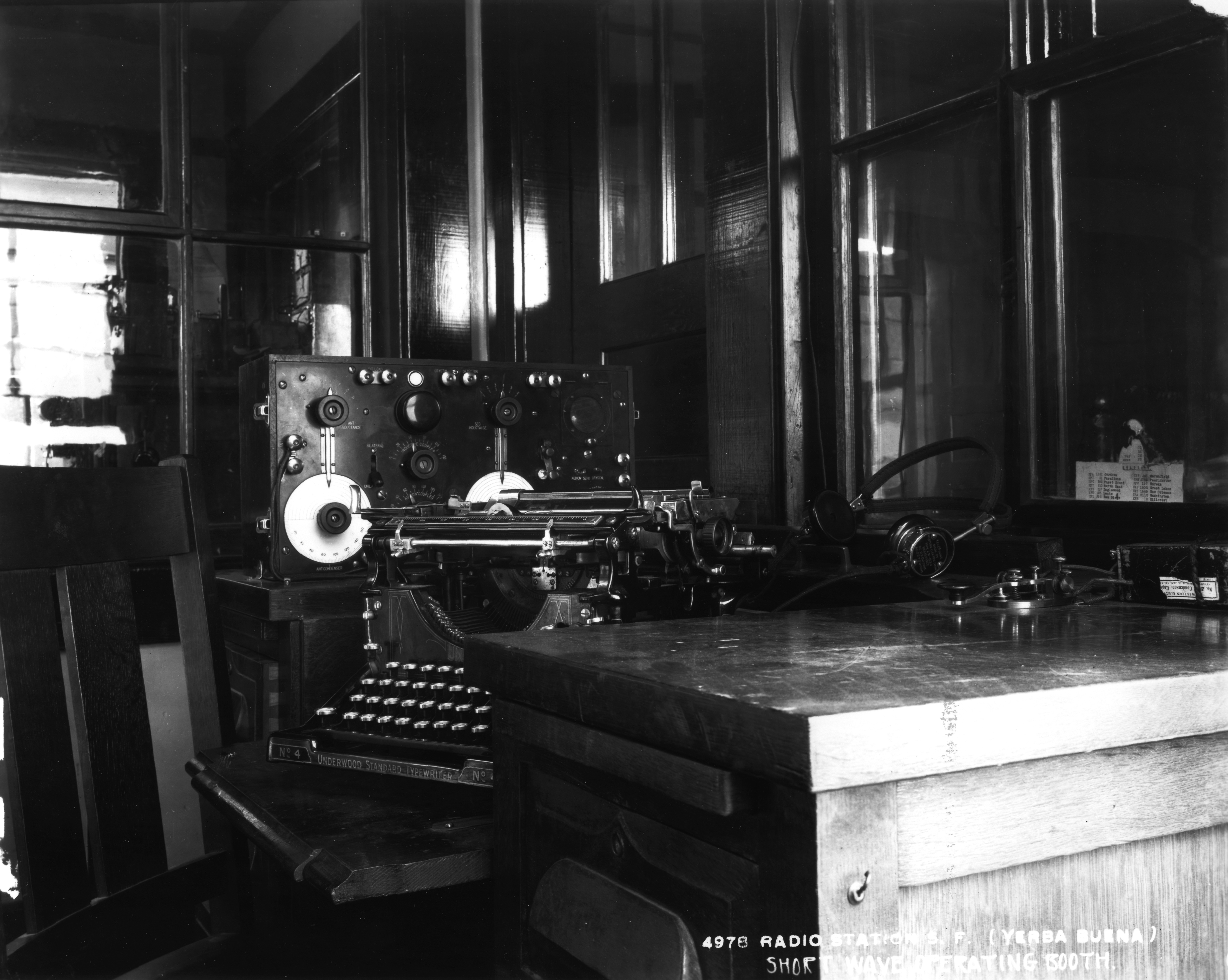
Short Wave Transmitter
yerba-1919-02.jpg (4264991 bytes)
Yerba Buena 1919 - Power House
yerba-1919-04.jpg (4396682 bytes)
Yerba Buena 1919 - Power House
yerba-1919-03.jpg (4498536 bytes)
--

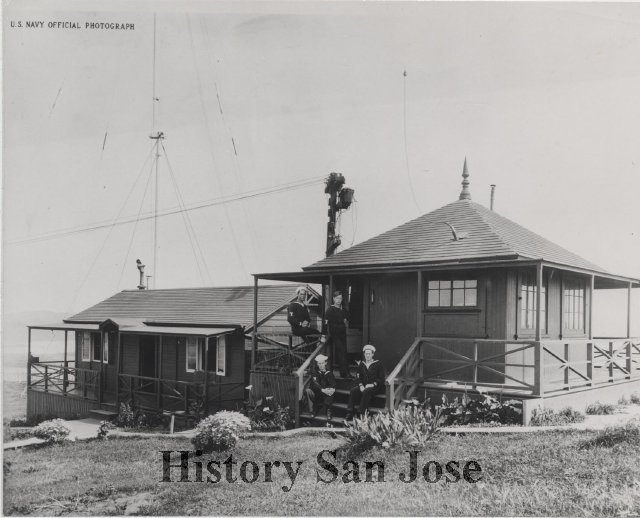
US Naval Radio Station Hillcrest - KPH (NWO?) -

Located in Daly City. Equipped with one 5 KW, 500 cycle quenched gap spark transmitter. The working wave was 600 meters . The set was also adjusted to 300 meters. Formerly a Marconi Company marine station, this station was taken over by the Navy on April 9, 1917 and operated for handling ship-shore commercial traffic. It was an important station and handled a considerable amount of traffic. The control of the transmitter was transferred to the Yerba Buena station in 1918. This station was acquired by the Government by purchase and all properties were transferred to the Government as of 15 May 1918.
- 1919 photos thanks to Gloria Conley

hillcrest-1919-04.jpg (3953997 bytes) hillcrest-1919-02.jpg (4019046 bytes) hillcrest-1919-03.jpg (4128898 bytes) hillcrest-1919-01.jpg (4684852 bytes)
hillcrest-1919-05.jpg (4558434 bytes) More photos and info -- --

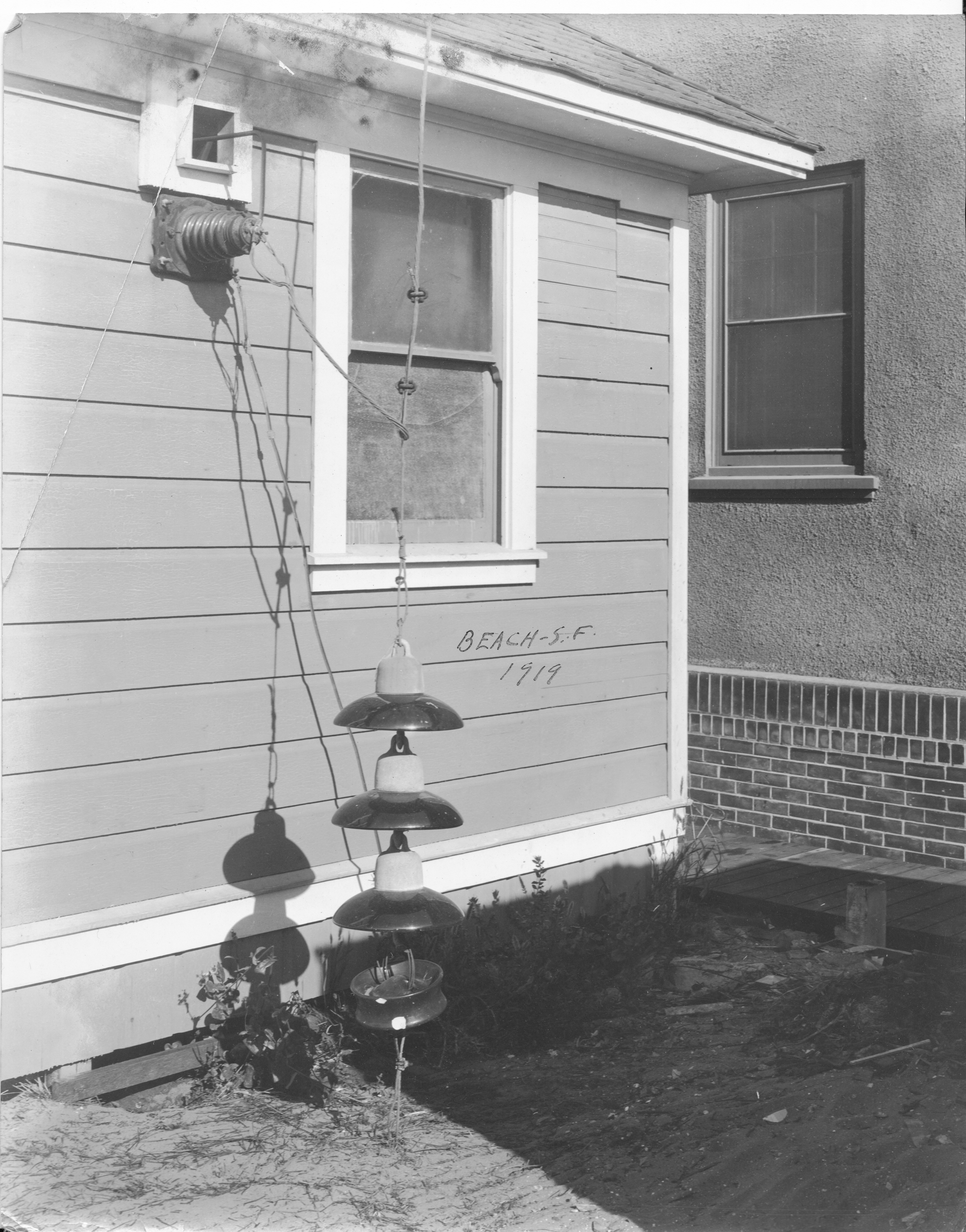
US Naval Radio Station, Beach (San Francisco) - KFS

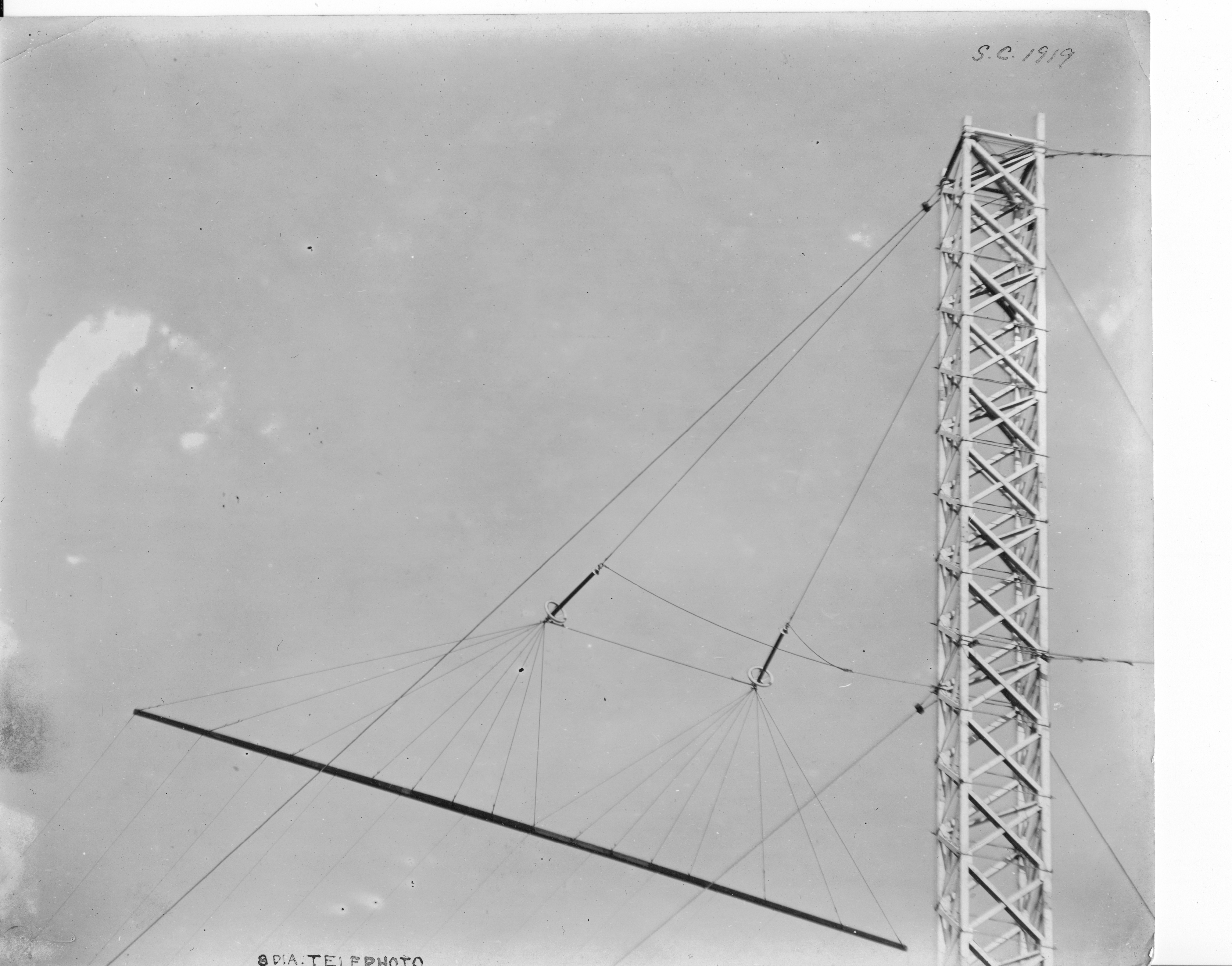
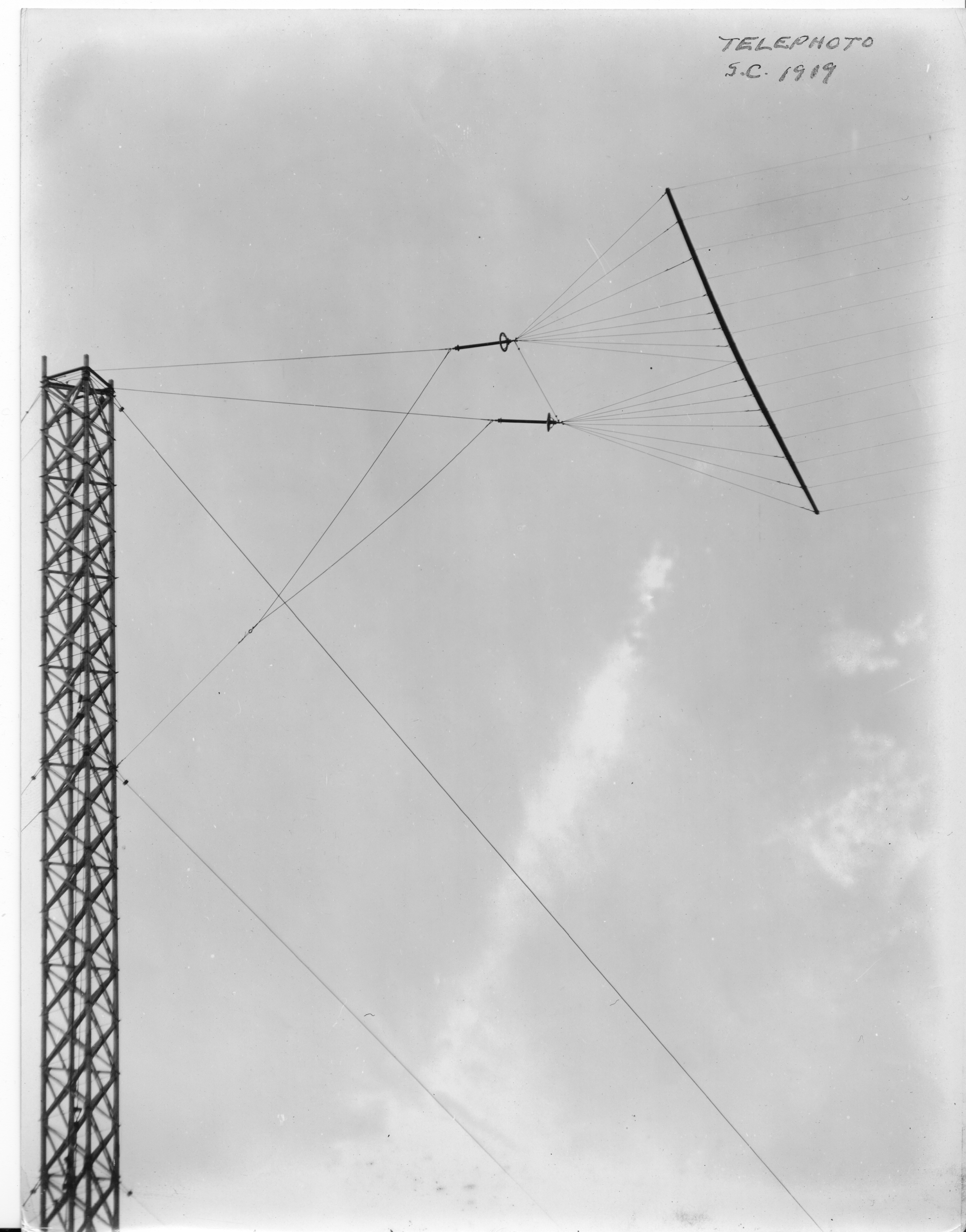
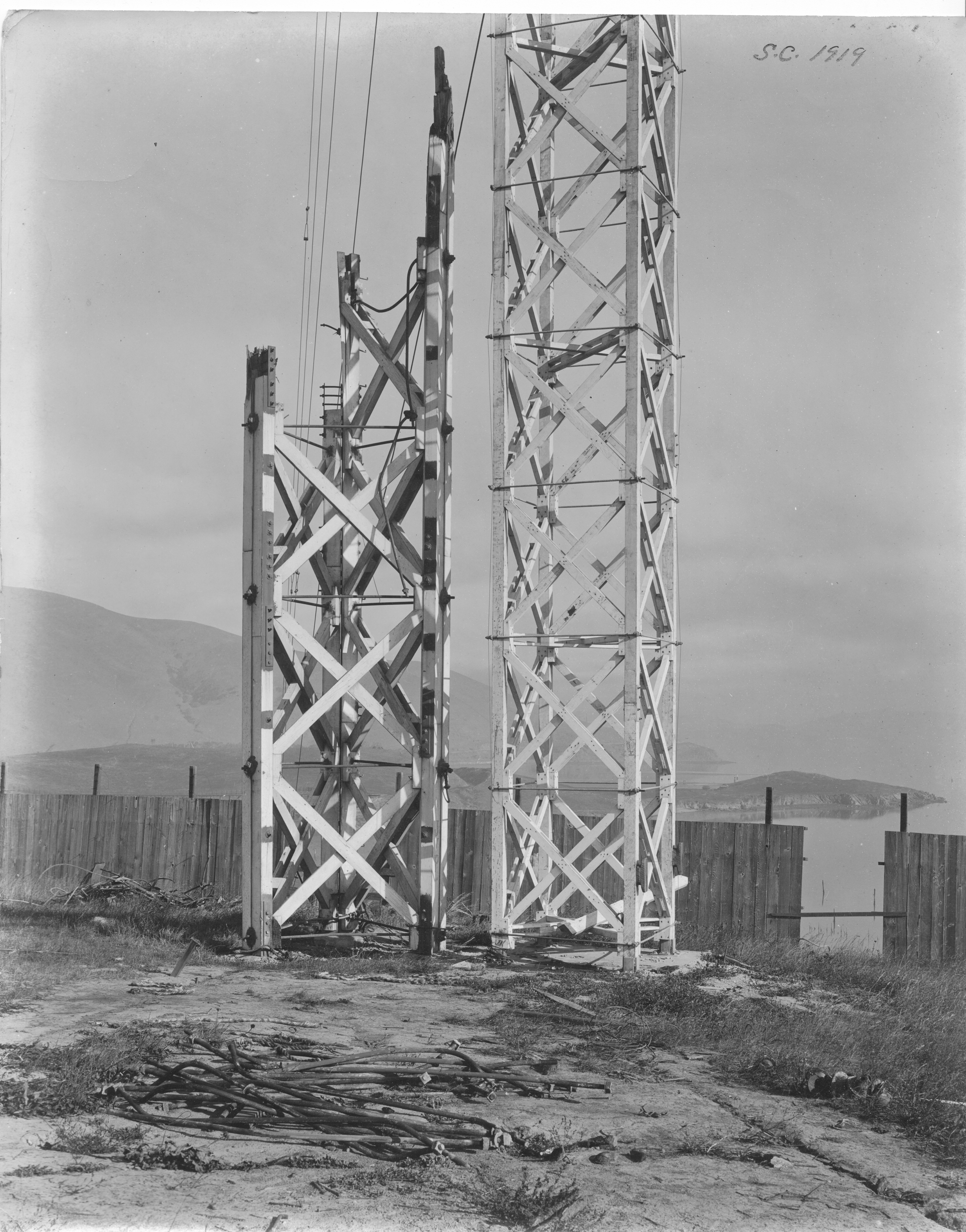
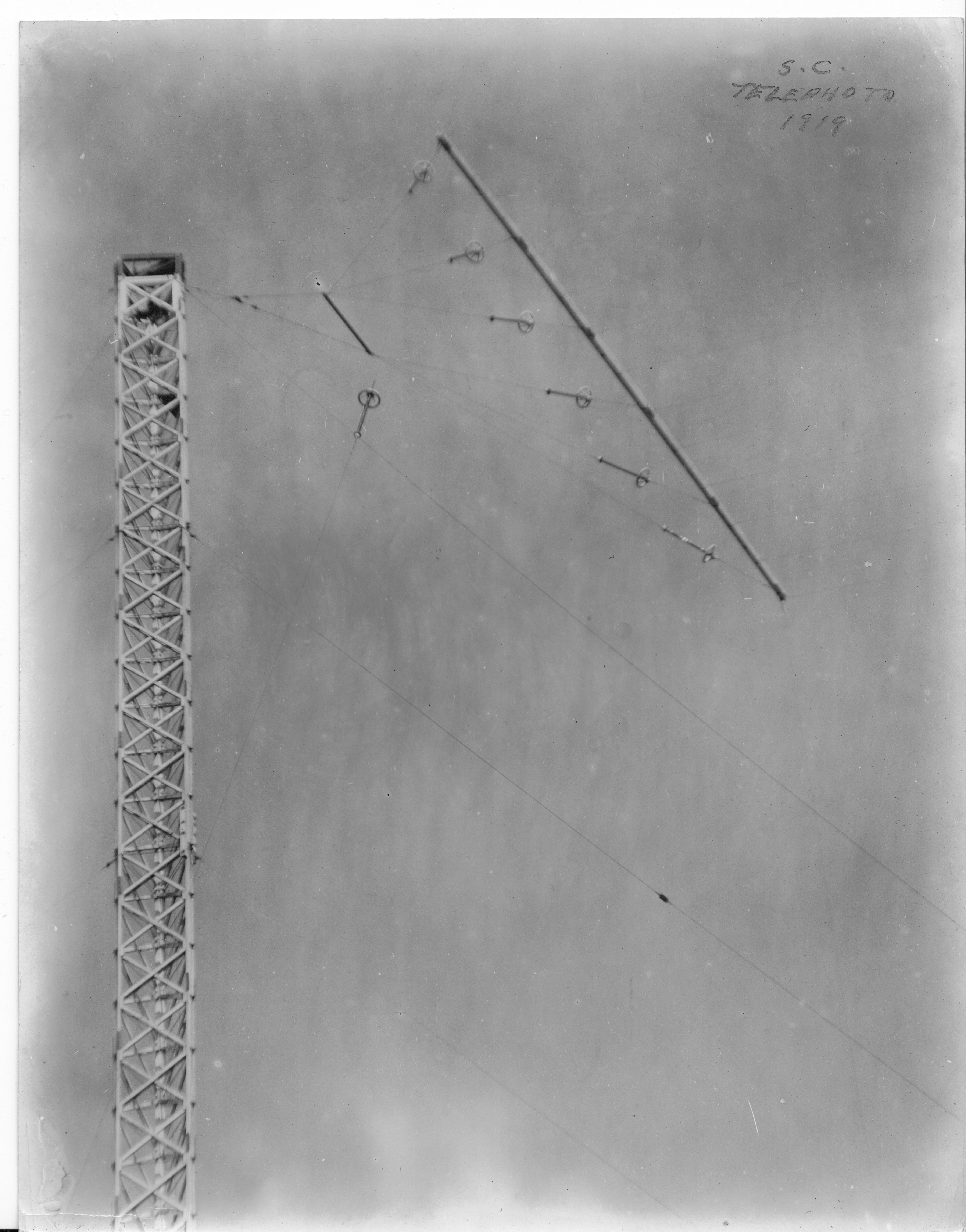
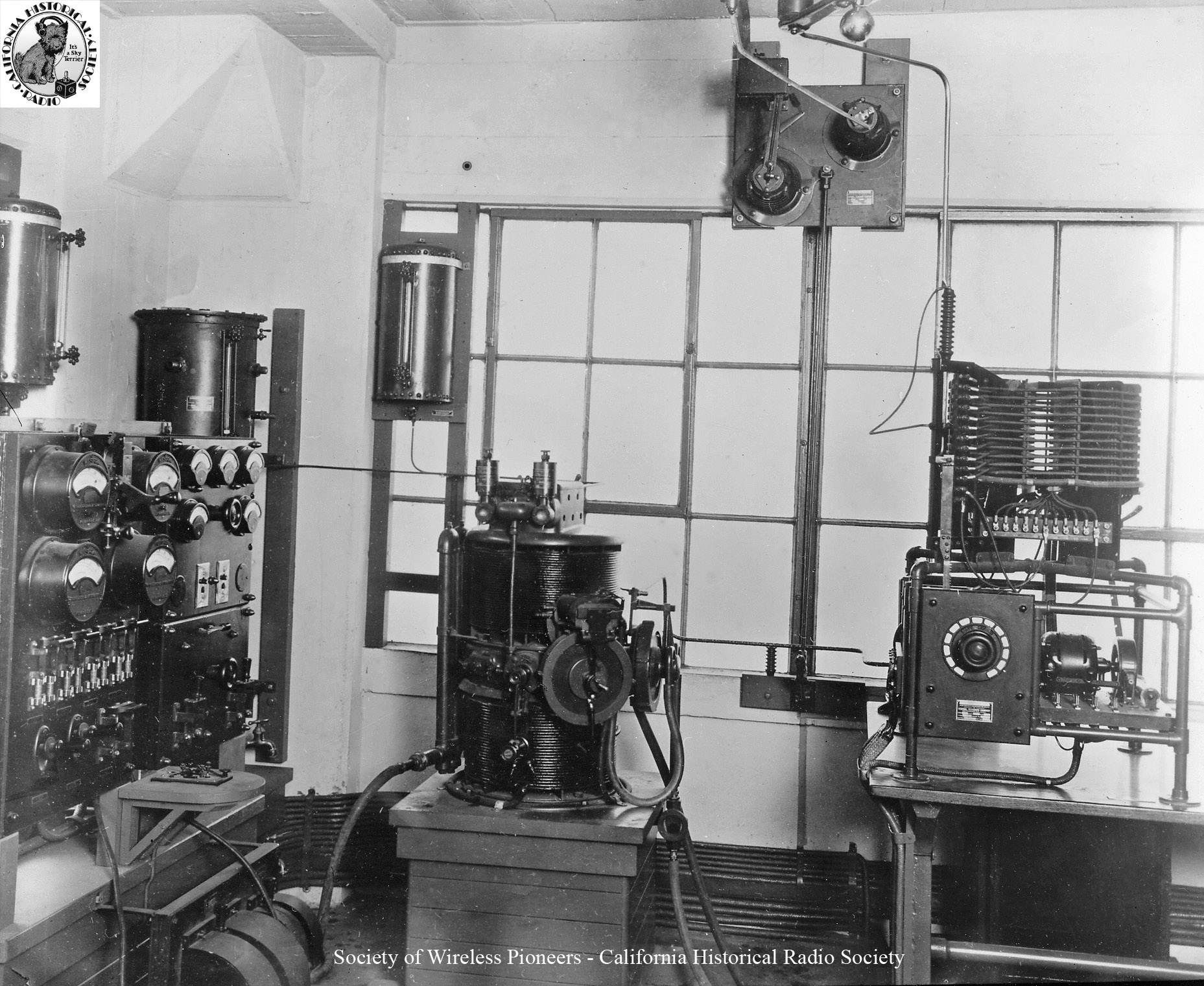
Located on the ocean beach at Great Highway and Noriega Street and 48th Avenue in San Francisco. Equipped with one 12 KW arc transmitter adjusted for 3000, 3350, 3500, 4000, and 4500 meters. The working wave was 3500 meters. The station was formerly utilized by the Federal Telegraph Company for point to point traffic with Lents and Inglewood, and with ships equipped with arc sets. The Navy utilized the station for handling commercial traffic with ships. The station was taken over by the Navy on April 7, 1917. Control of the transmitter was transferred to the Yerba Buena Naval Radio Station 25 February 1918. The station was acquired by the Government by purchase and all properties were transferred to the Government 15 May 1918.  - 1919 photos thanks to Gloria Conley

beach-1919-03.jpg (4222387 bytes) beach-1919-01.jpg (5077267 bytes) beach-1919-04.jpg (2992893 bytes) beach-1919-02.jpg (4273149 bytes)
beach-1919-05.jpg (4704272 bytes) more photos and info -- --

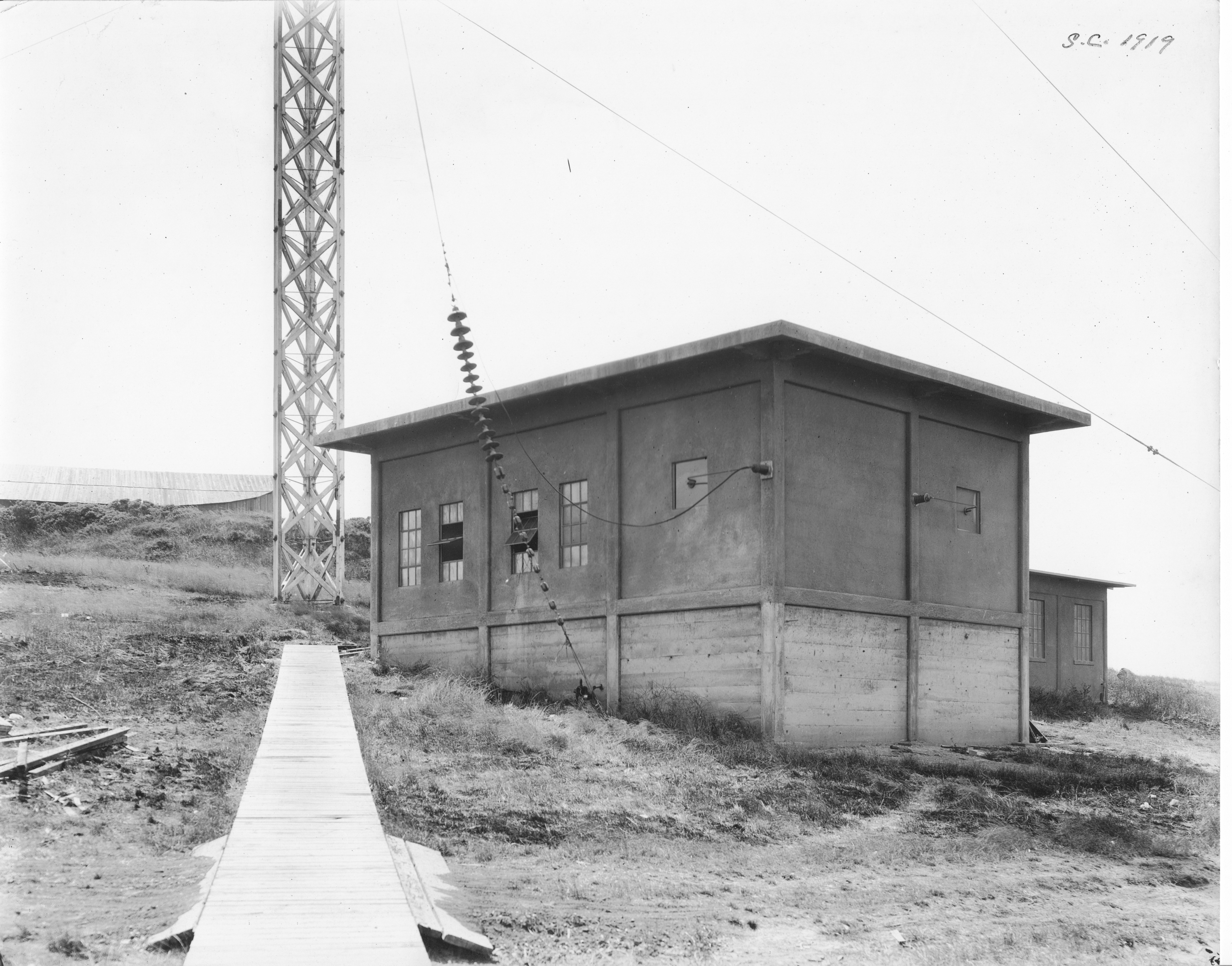
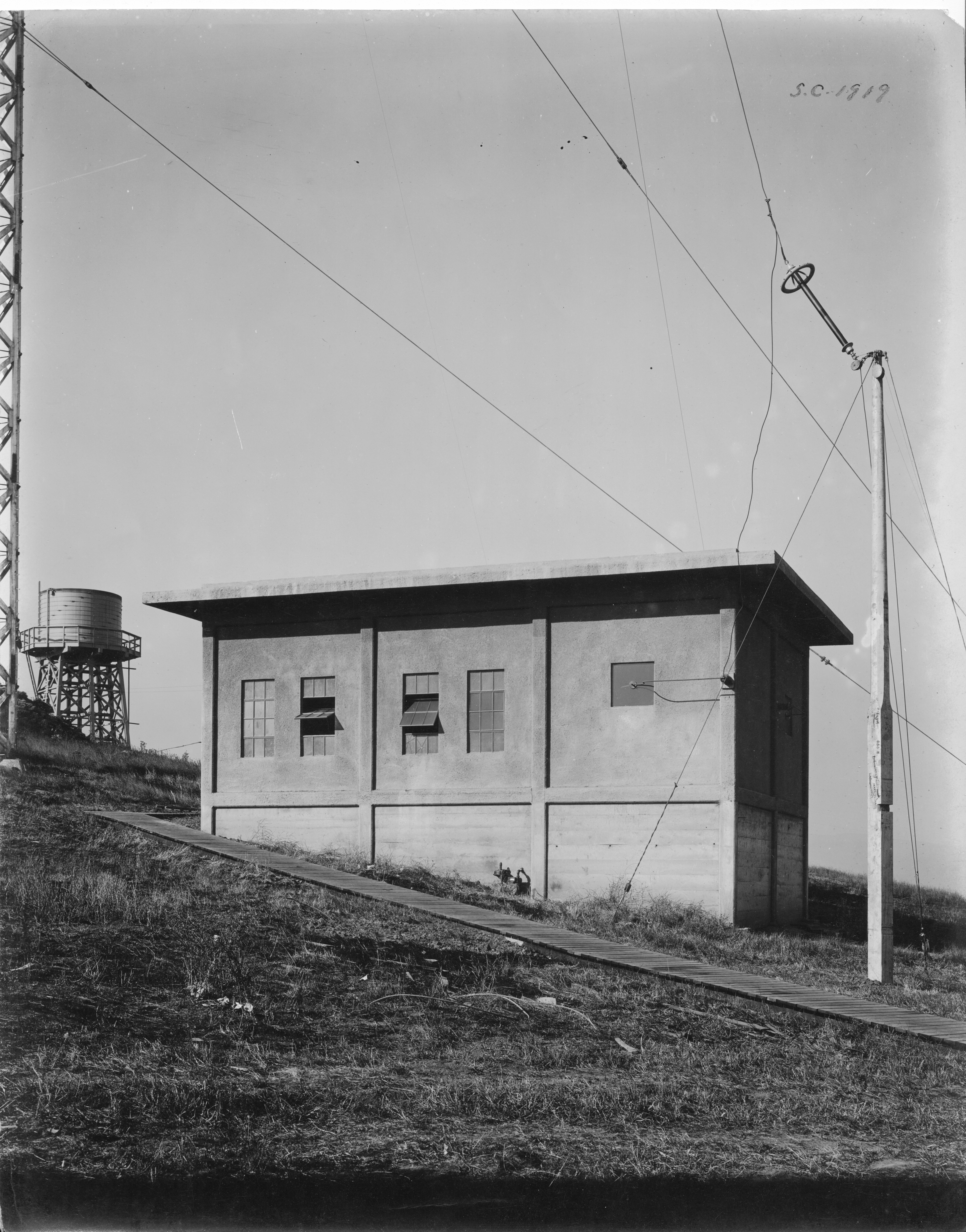
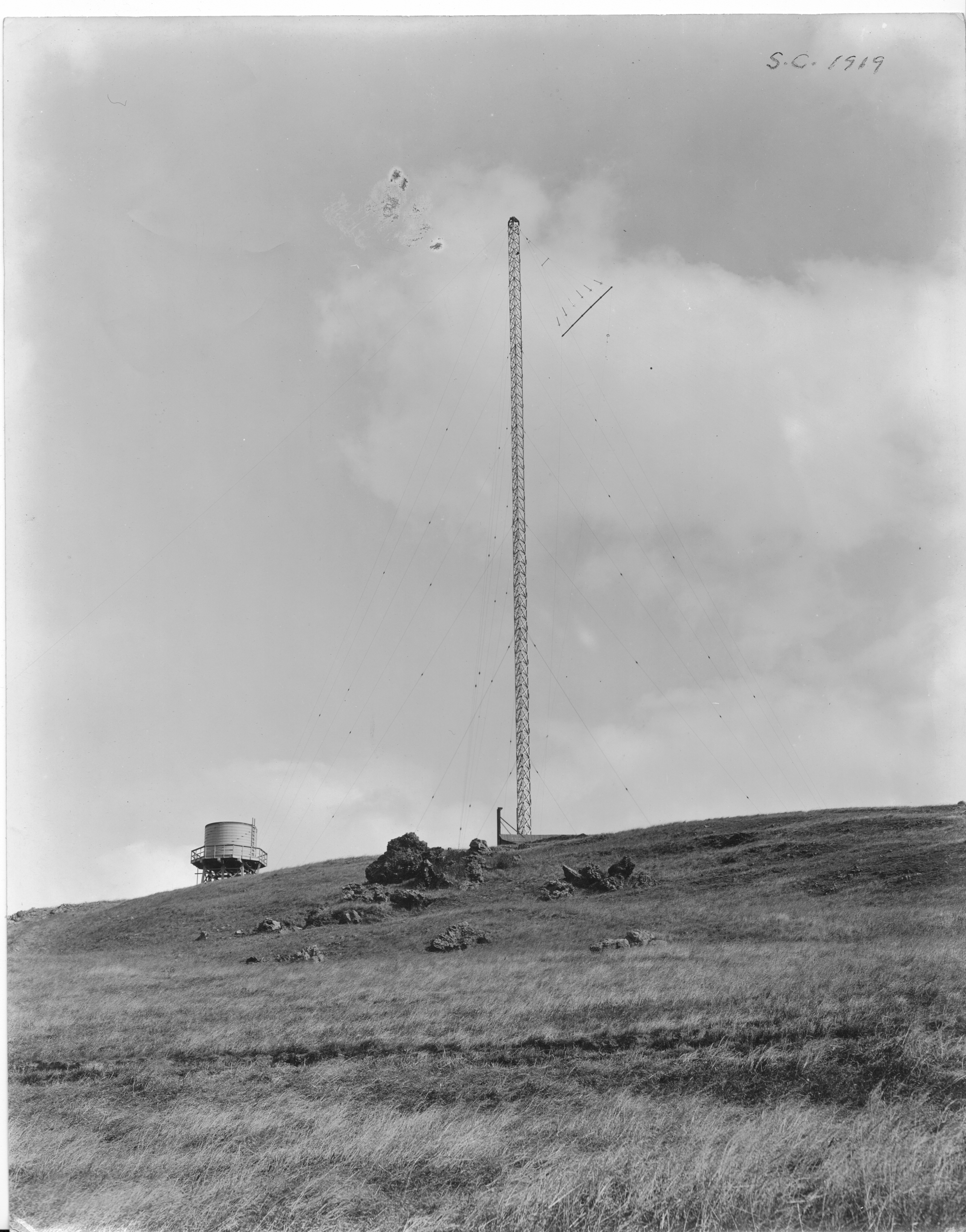
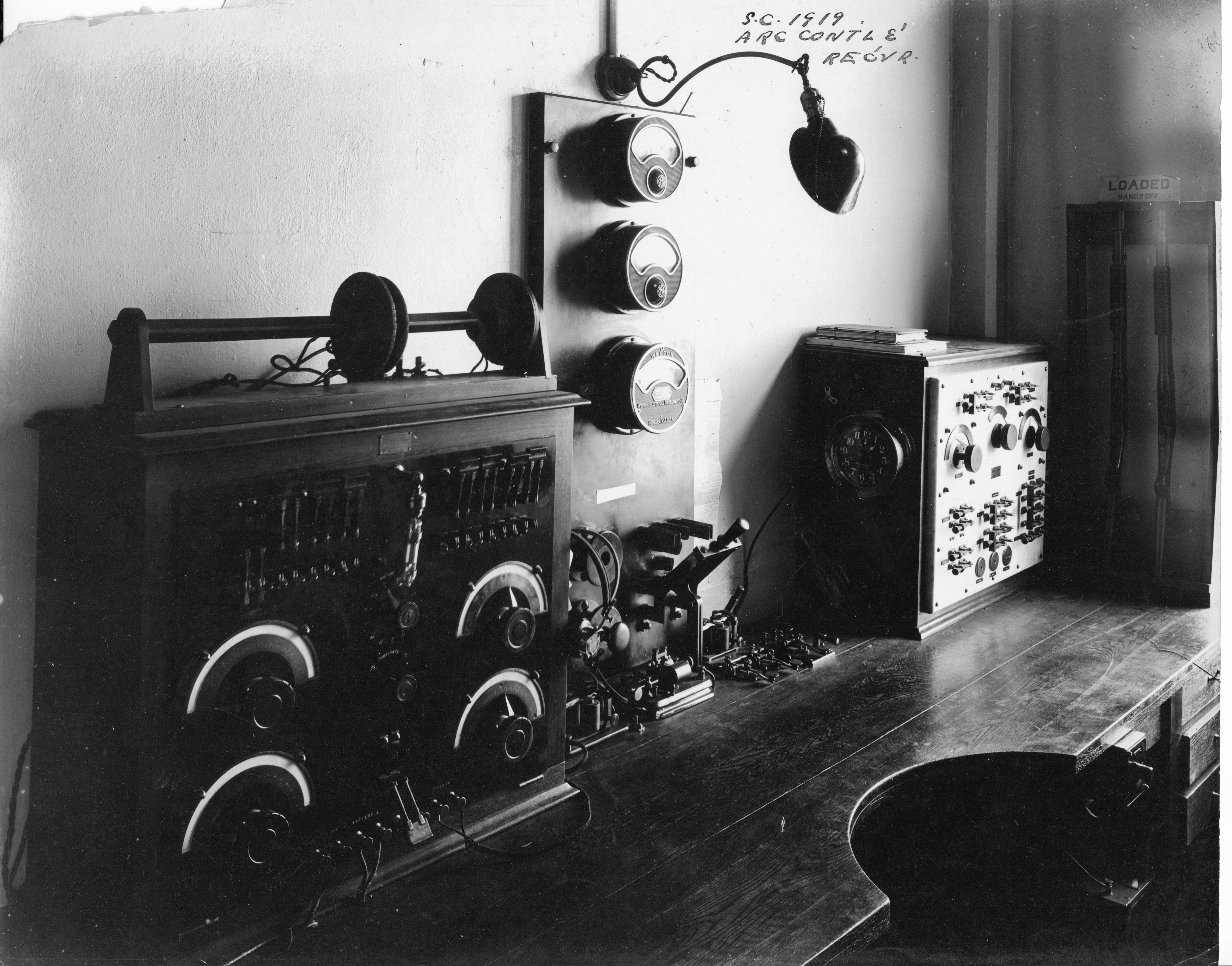
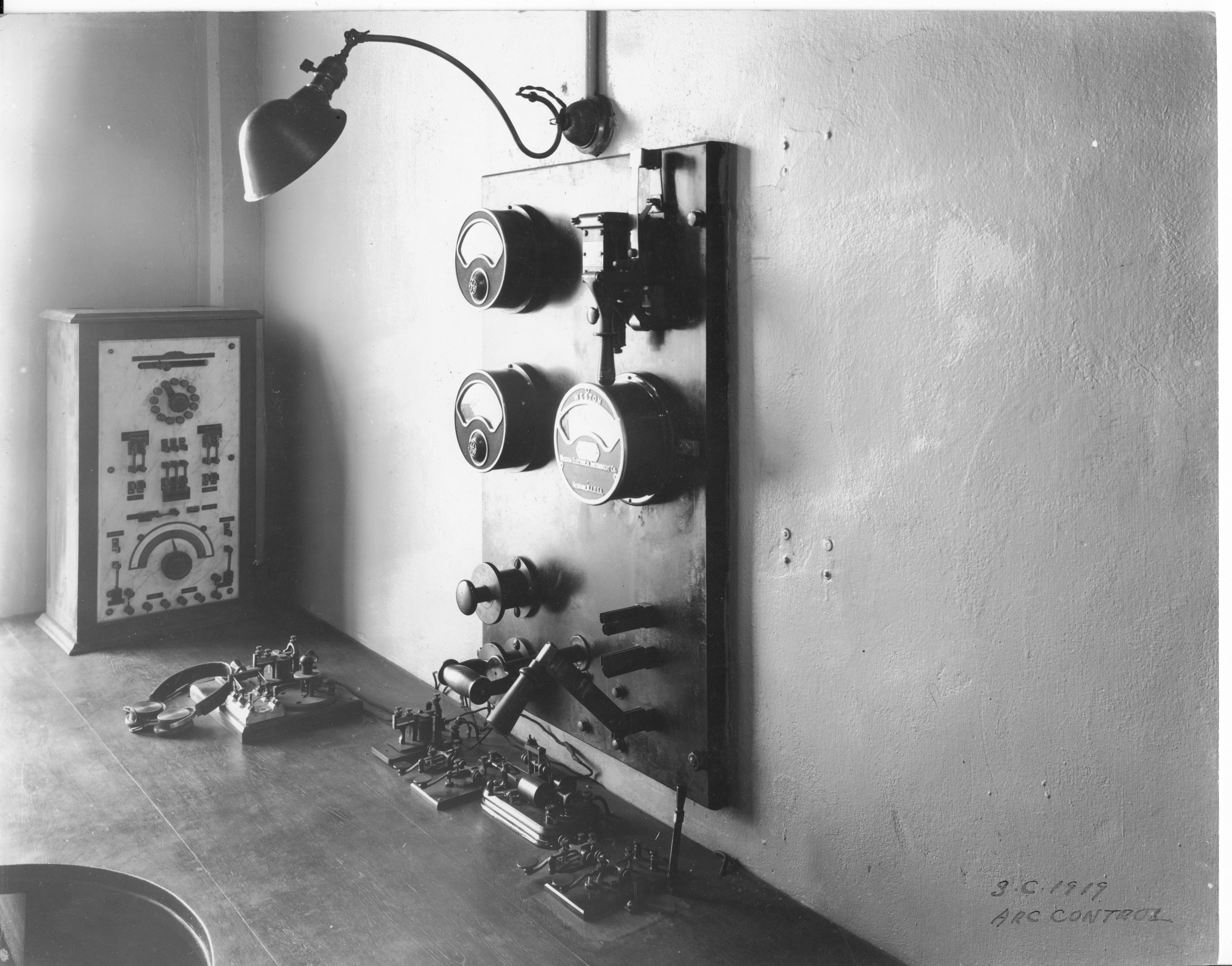
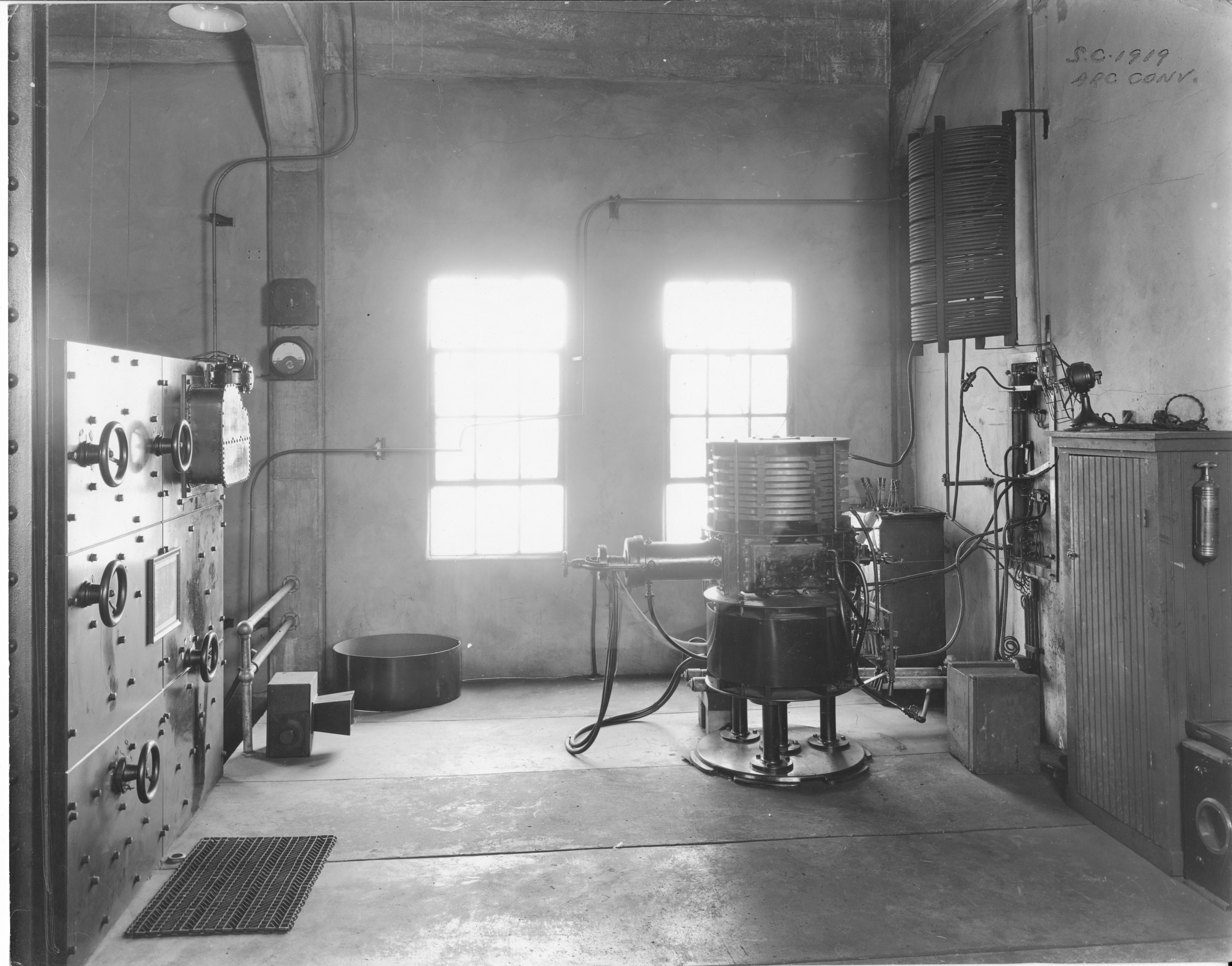
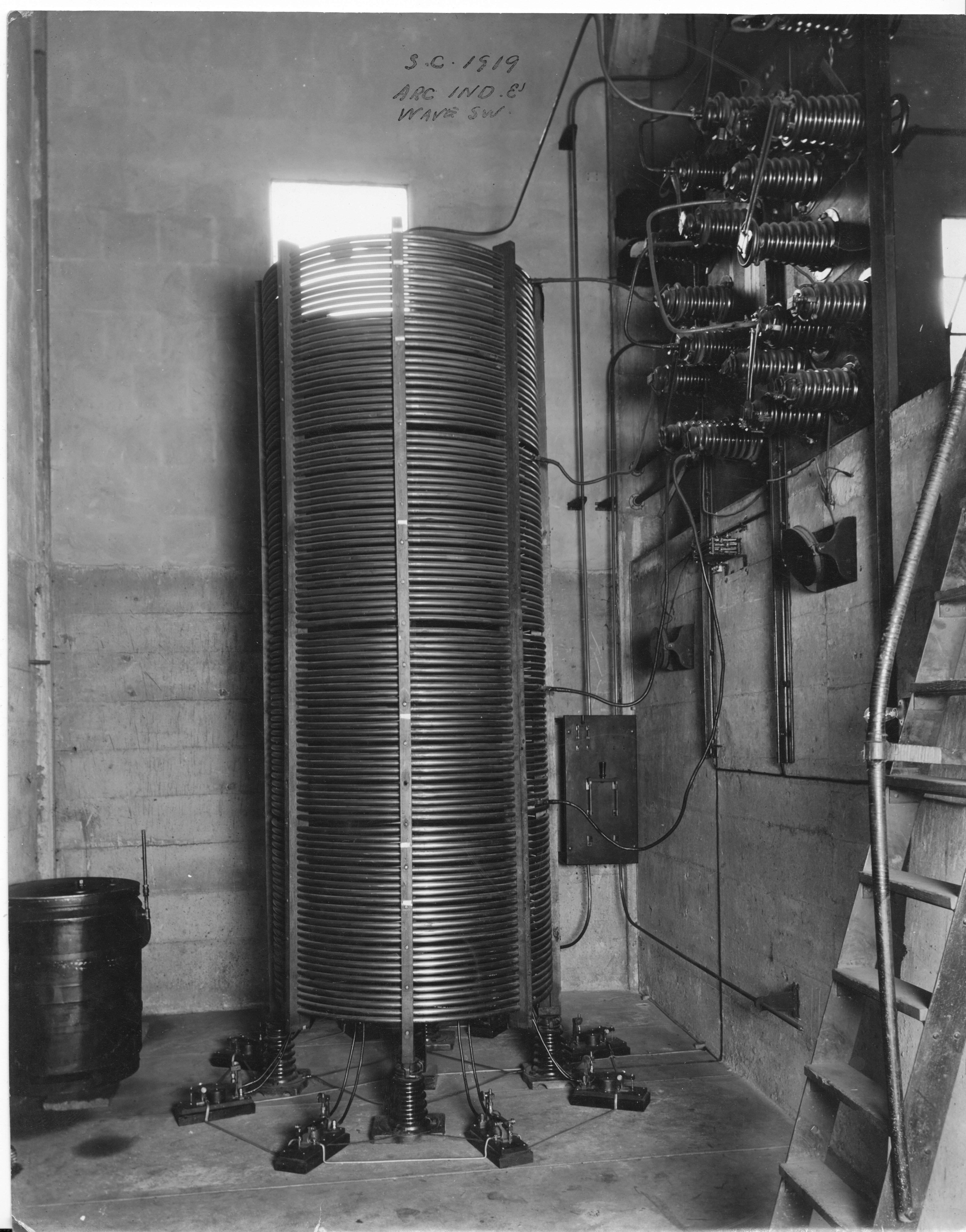
US Naval Radio Station South San Francisco - KSS

Formerly operated as a Federal Telegraph Company station with receiving and control station located in the Hobart Building in San Francisco. The transmitting station is located at South San Francisco and equipped with one 30 KW and one 40 KW arc transmitters, operated by remote control from the Hobart Building, adjusted for 6000, 8500, 10100, and 10600 meters. Until about 3PM the 10600 meter wave is used. During the afternoon, after 3PM, the 10100 meter wave is used . After 7 or 8PM, the 8500 meter wave is used. The 6000 meter wave is used as the last resort. Transpacific commercial traffic is handled between this station and the Heeia Point station in Hawaii. The Hobart Building control station was closed on February 25, 1918, and returned to the former owners . The control of the South San Francisco station was transferred to the Yerba Buena radio station. The South San Francisco station was acquired by the Government by purchase and all properties were transferred to the Government as of 15 May 1918.  - 1919 photos thanks to Gloria Conley

south-1919-14.jpg (3714587 bytes) south-1919-03.jpg (4026076 bytes) south-1919-09.jpg (5283868 bytes) south-1919-12.jpg (4126323 bytes)
Arc Control & Receiver
south-1919-13.jpg (5683294 bytes)
Arc Control
south-1919-02.jpg (4289466 bytes)
Arc Converter
south-1919-01.jpg (4249599 bytes)
Arc Inductor and Wave Switch
south-1919-10.jpg (4726970 bytes)
south-1919-08.jpg (3129326 bytes) south-1919-06.jpg (3030572 bytes) south-1919-04.jpg (4843562 bytes) south-1919-05.jpg (3793665 bytes)
Power House
south-1919-11.jpg (4171908 bytes)
Power House Switchboard
south-1919-07.jpg (3907081 bytes)
-- South San Francisco 1927 
sanfran-prewar-01.jpg (2460546 bytes)

Mare Island Transmitter Site - See also 1948 history article 

1904 - Radio Station (Call sign TG) established with Slaby-Arco transmitter at the HILL location
1912 - 5 KW quenched spark gap transmitter installed
1915 - 30 KW arc transmitter installed - call sign changed to NPG since Yerba Buena became the control station

Equipped with one 30 KW arc transmitter adjusted for these wavelengths : 4000 ( calling) , 4800 (working) , 6000, 8100, and 12000 meters ; and one 5 KW, 500 cycle quenched gap spark transmitter, adjusted for : 600 (commercial), 952 (calling), and 2400 (working) meters . Both transmitters were operated by remote control from the Yerba Buena station. Separate antennas were installed for the arc and spark transmitters . Receiving apparatus was also installed at the Mare Island station. There were four private landline circuits between Yerba Buena and Mare Island; three telegraph circuits for arc control, spark control and message circuit ; and one telephone circuit used as an order circuit for operation of apparatus and adjustment of wavelengths, etc . That circuit was bridged into the offices of the Pacific Coast Communication Superintendent at Yerba Buena and the Radio Officer at Mare Island . The arc set at Mare Island was used for communication with San Diego, Lents, Oregon, Puget Sound, Cordova and Great Lakes, Illinois. Traffic with Puget Sound, Cordova and Great Lakes was by schedule only. Traffic with San Diego was on a continuous call basis . The spark transmitter at Mare Island was used to communicate with Farallon Island, Eureka, Marshfield, Oregon (night only), North Head (night only), and with ships equipped with spark sets . Time signals were transmitted simultaneously daily at noon and 10 PM, 120th meridian time, on both arc and spark transmitters on 4800 and 2400 meters. This was accomplished by the Mare Island station switching control of both transmitters direct on the Western Union wire which was connected to the Naval Observatory at Mare Island . The station broadcast local weather conditions, storm warnings and hydrographic information in accordance with Radio Regulations .

1920 - Construction of new Power House, Operating Building, and three 450' towers at HIPOWER location
1920 - 100 KW Arc transmitter moved from Tuckerton NJ, 40 KW arc transmitter moved from South San Francisco
1922 - additional 100 KW Arc transmitter and two additional 450' towers installed
1942 - Receiving equipment and functions moved from Mare Island to Skaggs Island
1945 - SSB transmitters installed for Washington and Honolulu circuits (multi-channel RATT)
1961 - The five 450' towers and the LF transmitters were removed - about 60 HF transmitters remained in operation.
1965 - Operations moved to Dixon CA
Hill Station 1906
mare-island-hill-1906-01.jpg (61401 bytes)
Mare Island 1904
mare-island-1904-01.jpg (1347833 bytes)
More Mare Island history

Mare Island 1919 photo

March 1949
mare-island-hf-01.JPG (175490 bytes)
January 1940
mare-island-1940-1601.jpg (113857 bytes)
1930's
mare-island-prewar-1601.jpg (830046 bytes)
==
1921 view from antenna tower
mare-island-tower-01.jpg (1418226 bytes)
100kw towers - December 1920
mare-island-122720.jpg (2208289 bytes)
1929 "Beam Antennae"
mare-island-70738.jpg (2488437 bytes)
Beverage antenna for diversity receiver
mare-island-NH-70714.jpg (3095799 bytes)
Mare Island 1917 - receiving equipment
mare-island-1917-02.jpg (55824 bytes)
Mare Island 1917 - Hill Station?
mare-island-1917-03.jpg (51029 bytes)
mare-island-1917-04.jpg (51704 bytes) 100kw arc converter - 1917

mare-island-1917-01.jpg (54991 bytes)


HF Transmitter Station - 1948 -Wing A
mare-island-hf-1948-01.jpg (545017 bytes)
HF Transmitter Station - 1948 - Wing B
mare-island-hf-1948-02.jpg (548836 bytes)
HF Transmitter Station - 1948 - Wing C
mare-island-hf-1948-03.jpg (919100 bytes)
==
Building 505 HF Transmitters - photos and plans - main link -

mare-island-505-dwg-01.jpg (198094 bytes)

mare-island-505-01.jpg (82744 bytes) mare-island-505-02.jpg (129558 bytes) mare-island-505-03.jpg (84349 bytes)

Skaggs Island - 1945 and 1948 info

skaggs_1945_10_big.jpg (65516 bytes) skaggs_1945_35_big.jpg (59945 bytes) skaggs_1945_11_big.jpg (74076 bytes) skaggs_1945_12_big.jpg (79686 bytes)
RBP Diversity receivers at Skaggs Island
skaggs_1945_rbp.jpg (64031 bytes)
skaggs_1945_rbp-2.jpg (67934 bytes) skaggs_1945_rbp-3.jpg (74652 bytes) skaggs_1945_13_big.jpg (73111 bytes)
skaggs_1945_38_big.jpg (93034 bytes) skaggs_1945_39_big.jpg (85181 bytes) skaggs_1945_40_big.jpg (83003 bytes) Skaggs Island 1948
skaggs-1948.jpg (5000483 bytes)
skaggs_1945_42_big.jpg (64651 bytes) skaggs_1945_43_big.jpg (94346 bytes) skaggs_1945_45_big.jpg (71057 bytes) skaggs-2008-01.jpg (24317 bytes)
From 1948 BuShips Electron Magazine - 
   Skaggs Island houses three activities: 1-Receiving Activity, 2-Communications Supplementary Activity, and 3-Security Activity. The reservation consists of 3,300 acres of flat and level land surrounded by salt water sloughs and protected therefrom with suitable levees. It is approximately 28 air miles (49 road miles) from the San Francisco Control Station and 8 air miles (29 road miles) from Mare Island Naval Shipyard. The quarters and station maintenance facilities area is in the northeastern corner. The main operating building is located near the geometric center.
   The main operating building is of reinforced concrete measuring 80' x 85' and consists of two floors and a basement. It is of splinter-proof construction with no windows below the second floor. It was originally designed and equipped to be a combined major diversity receiving station and complete emergency control station. The lower floor was intended for operating activities. Each room therein is completely shielded with sheet copper. The basement was intended for wireways, conduits, and other services. The second floor was intended for offices, storerooms and air conditioning equipment.
    The 80' x 30' receiving room was designed to
accommodate four rows of single or diversity receivers. The supervisor's desk, audio, radio frequency, and power panels as well as the two crystal controlled clocks are located at one end of the room. At the other end of the room are located emergency Boehme positions and ships operating table. Because experience has indicated that it is expedient to have the ship-to-shore operators situated where they can control their own receivers, ships tables (where manual and radio-teletype operators handle this type of circuit) are located adjacent to the wall originally intended for the fourth row of receivers. Receivers and ships tables are above rows of concealed prefabricated holes in the floor which convey. wires and cables to a three-tier cable tray slightly to one side of the holes.
    The Communication Supplementary Activity occupies the 80' x 35' room originally equipped for control purposes. This activity also occupies additional operating space on the second floor. This activity has sole occupancy of the Special Project Building surrounded by 19 rhombic antennas and the DA J building which are remotely located. Additions are in the planning stage.
    The Security Activity occupies space on the second floor. It is well equipped with a model LAM precision frequency measuring equipment as well as other necessary facilities to measure quickly and accurately any received frequency from the very low to ultra high. Facilities permit of monitoring several types of transmission including teletype to assist in its program to observe any irregularities in procedure.
    The main antenna system consists of three spaced rosette groups of rhombics. Each of three groups was originally of slightly differing design: a-single wire horizontal, b-3-wire horizontal, and c-single wire sloping. The intention was to service-test the three types to determine the best. The 3-wire type appears to be most satisfactory.

NPW Eureka

 ca. 1913-15
eureka-82992.jpg (3701032 bytes)

Another photo of Eureka 1913  

-- --