 |
 |
 |
 |
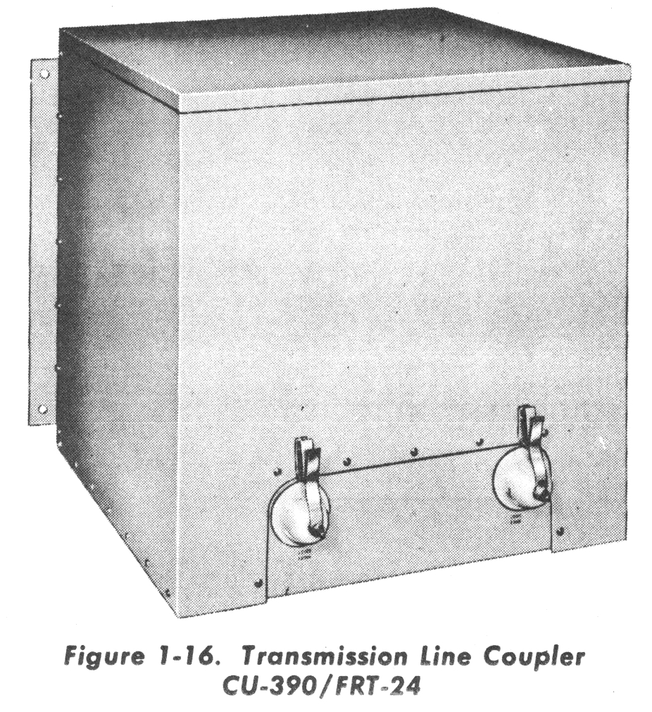
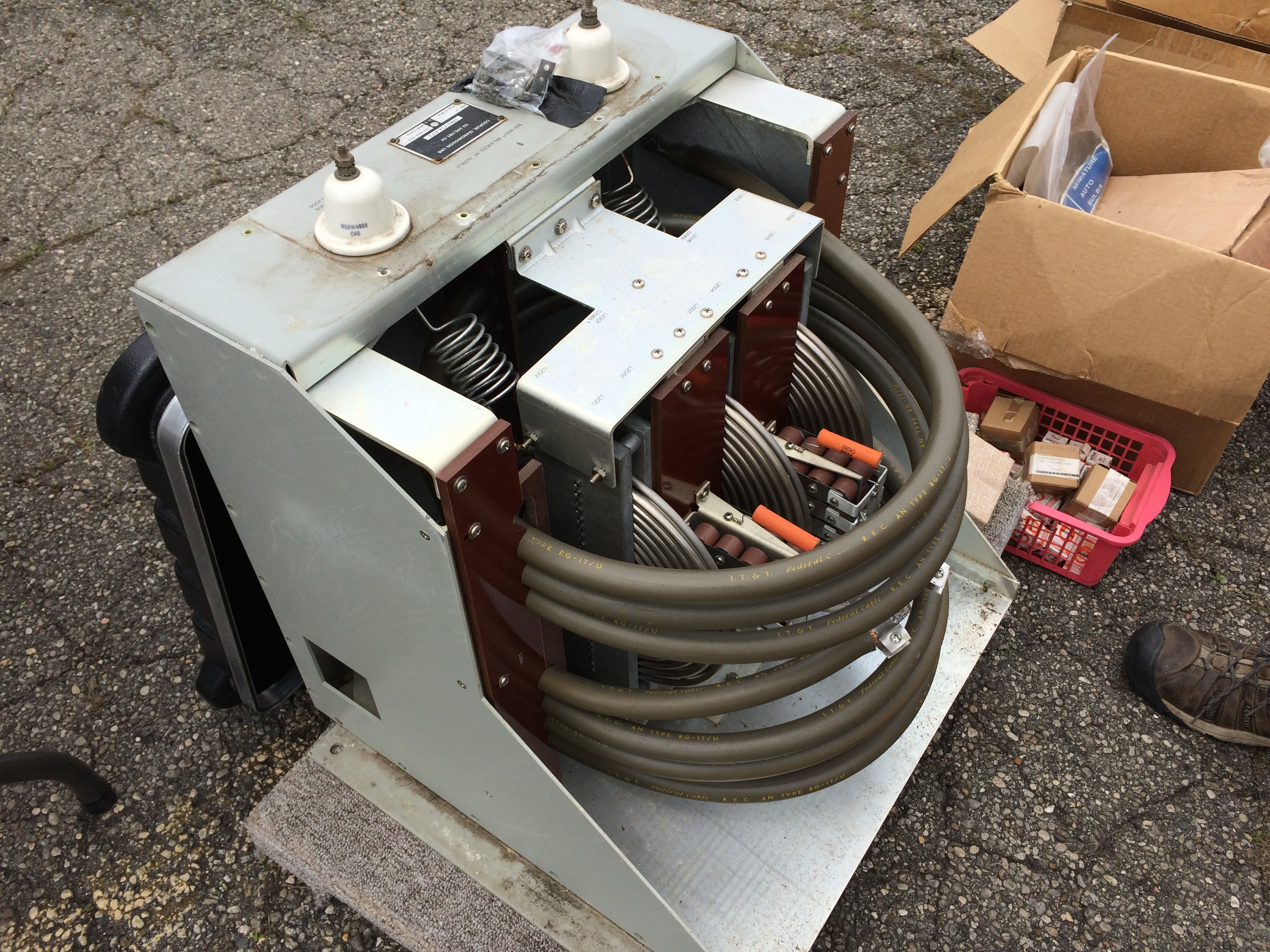
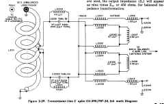
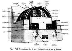
| TRANSMISSION LINE COUPLER CU-390/FRT-24 (see
figure 2-29) .-The Transmission Line Coupler is a device that provides
both balancing and impedance transformation. It matches the unbalanced
52-ohm output from the pi-L coupler of the transmitter to a balanced
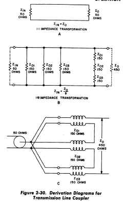
600-ohm, two-wire line feeding the antenna system Figure 2-30, A through
C, illustrates the basic theory from which this coupler was derived. Figure 2-30A shows an ideal long transmission line whose input
impedance (Zin) is equal to the terminating or output impedance (Zo) and
also shows an ideal matching transformer with a balanced input and a
balanced output and an impedance-matching ratio of 1:1. If long, equally
terminated transmission lines are connected in parallel at one end and in
series at the other end, the output impedance (Zo), as shown in figure
2-30B, the result is the same as putting lumped resistances in series at
the Zo end and in parallel at the Zin end. The impedance transformation at
the input end (looking from the coupler to the transmitter) is step down,
and at the output (looking from the coupler to .the actual antenna
transmission line), step up; in either case, it varies as the square of
the number of transmission lines used regardless of whether the circuit
constants are lumped or distributed. Since three separate transmission
lines are used, the output impedance (Zo) will appear as nine times Zin,
or 450 ohms, for balanced impedance transformation. |
| Figure 2-30C shows the equivalent circuit for
the conditions represented in figure 2-30B except that an unbalanced input
is fed through the coupler to a balanced output; the circuit also uses
artificial transmission lines having lumped constants instead of long
terminated lines. If a 600-ohm load is connected across the
450-ohm·output of this device, a standing-wave ratio (SWR) of 1.33:1
(600/450) will exist, assuming a balanced input and output condition.
In practice, this is very difficult to achieve with antennas and
transmission lines, particularly when they have to work over a wide
frequency range such as 2 to 30 mc. Any unbalanced currents in the transmission
line would cause a high standing-wave ratio, with subsequent distortion of
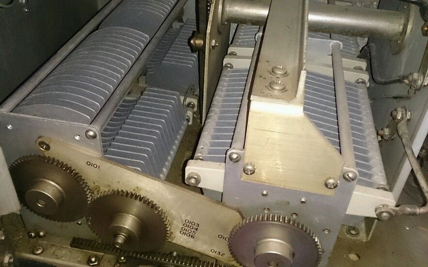
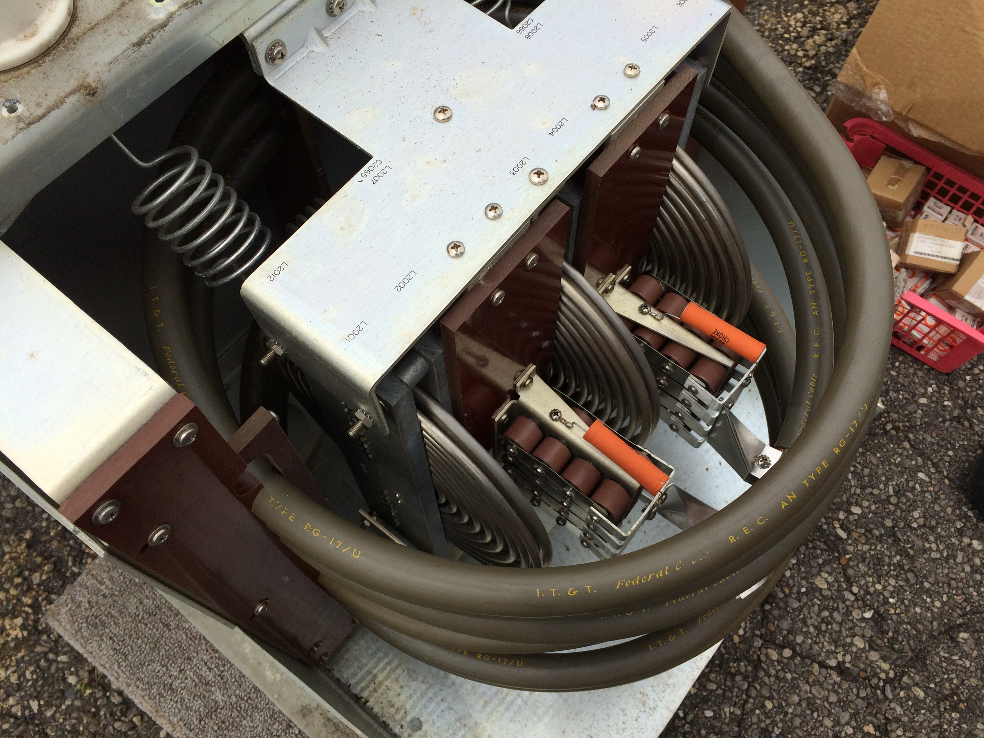
the radiation pattern. Lumped transmission lines L2001 and L2002, L2003
and L2004, and L2005 and L2006 are arranged so that their windings offer
opposition 'to the flow of unbalanced currents (always in the same
direction) and no opposition to the flow of balanced currents (always in
opposite directions) . Balance is obtained by the use of a coil Balun,
L2011, to couple the matching unit to the unbalanced 52-ohm transmitter
output jack (P2001). |
 |
| This Balun consists of a coaxial line wound as
an inductance and connected as shown in the schematic in figure 2-29. As
connected, the center conductor of the grounded half of this coil is not
used, and the circuit operates as if it were comprised of two tank
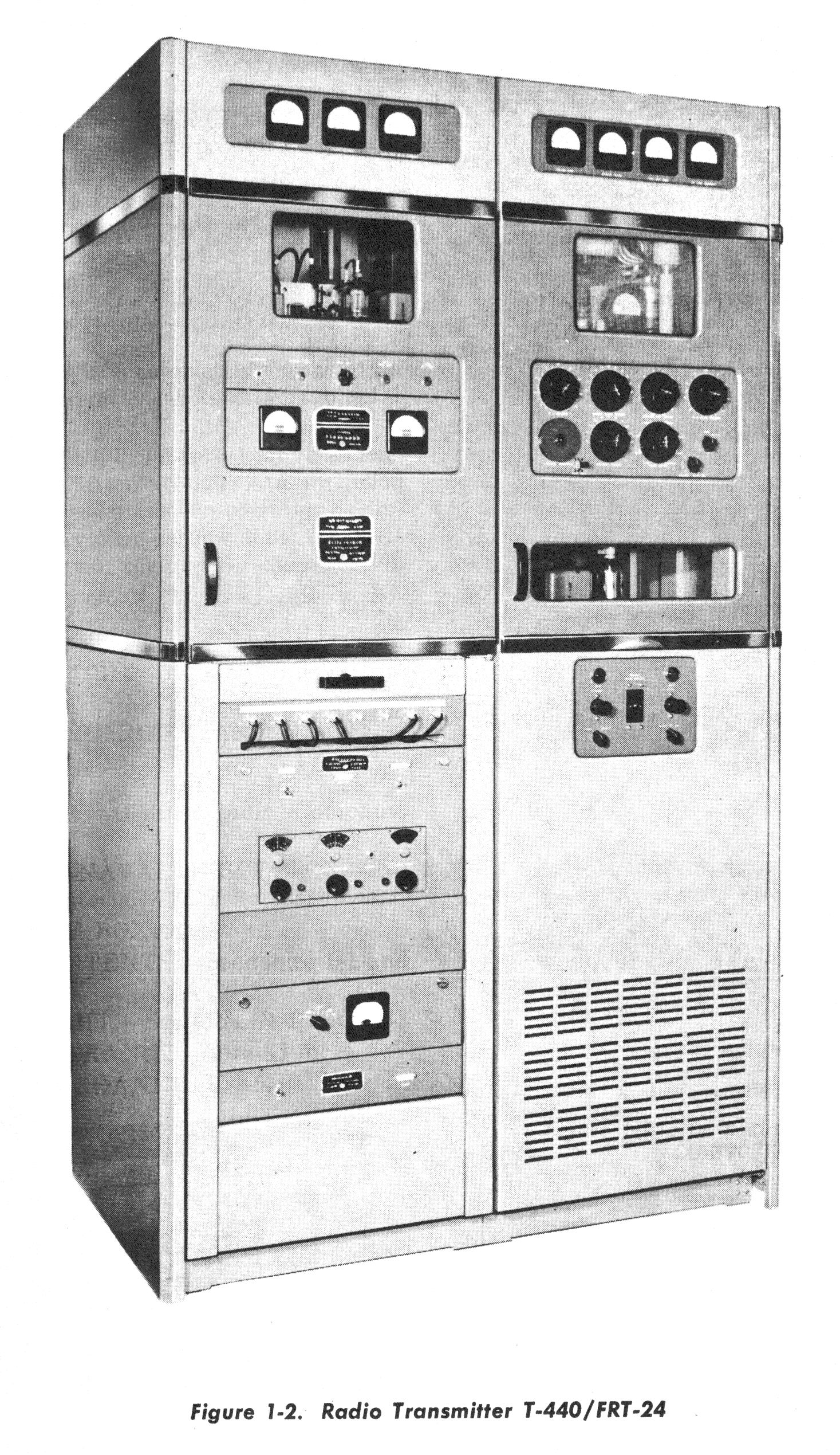
circuits balanced to ground. The unbalanced 52-ohm output, taken from
Radio Transmitter T-440/FRT-24 through an RG-17/U coaxial cable and
connector J107, is introduced to a 52-ohm balanced circuit, L2011, which
converts this output to a balanced 52-ohm input. This input impedance is
then stepped up in impedance by a device similar to the type discussed
above. L2011 is made up of two sections of coiled r-f coaxial cable, which
together with their distributed capacitances, act as two parallel resonant
circuits equivalent to a center-tapped input over the entire operating
range to maintain line balance. L2011 covers a 4 :1 range in frequency;
the use of capacitors C2001 through C2064 ( 64 capacitors in all) and
coils L2009 and L2010 extends the low-frequency range and the over-all
coverage to 15:1. An improvement in the standing-wave ratio is obtained by
the use of tuned circuit C2065 and L2007, in series with the sections of
artificial transmission line consisting of spiral windings L2002 and
L2003; and by the use of tuned circuit C2006 and L2008, in series with the
other sections of artificial transmission line consisting of spiral
windings L2004 and L2005. Two loading coils (L2012 and L2013) are used to
extend the frequency range of the coupler to 31.25 mc at the
high-frequency end of the range, to prevent an otherwise
rapidly rising SWR at 30 mc. These series
loading coils, together with the feed-through bowl
capacitance of 3.6 micromicrofarads to ground (existing
at E2003 and E2004, and E2005 and E2006,
respectively), also form a small L-type network
that matches the 450-ohm theoretical output impedance
of the coupler to a 600-ohm load. A horn gap,
E2013 and E2014, connected to one side of the
balanced line, and E2015 and E2016 connected
to the other, protect the equipment from .damage
due to extremely high voltage surges such as
occur during lightning storms. |