"The Navy's Tone-Modulated Radio
Teletype
System"
- BuShips Journal September 1956
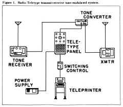
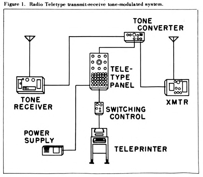
Figure 1. Radio Teletype transmit-receive tone-modulated system. |
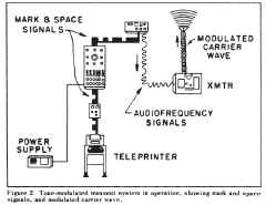
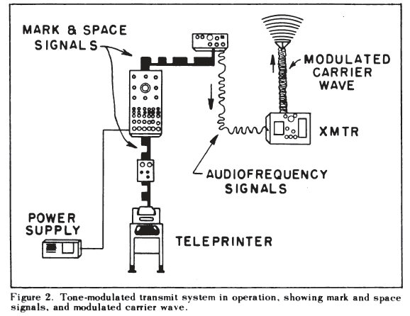
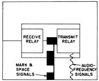
Figure 2. Tone-modulated transmit system in operation, showing mark and space
signals, and modulated carrier wave. |
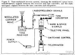
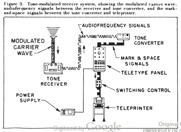
Figure 3. Tone-modulated receive system, showing the modulated carrier wave,
audio frequency signals between the receiver and tone converter, and the mark-and-space signals between the tone converter and teleprinter. |

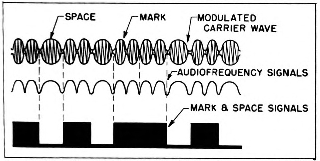
Figure 4. Pictorial representation of mark-and-space signals, equivalent
audio frequency signals, and audio frequency signals modulated on the carrier wave. |

Figure 5. Tone converter in transmit position, with the mark-and-space signals entering converter in the transmit relay and coming out as
audio frequency signals. |
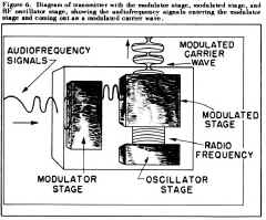
Figure 6. Diagram of transmitter with the modulator stage, modulated stage, and
RF oscillator stage, showing the audio frequency signals entering the modulator
stage and coming out as a modulated carrier wave. |
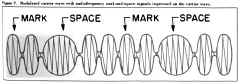
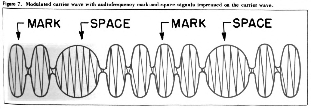
Figure 7. Modulated carrier wave with audio frequency mark-and-space signals impressed on the carrier wave |
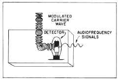
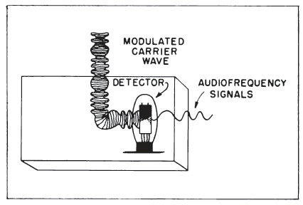
Figure 8. Representation of receiver with modulated RF carrier wave entering receiver, being detected and
changed to audio frequency mark-and-space signals. |
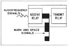
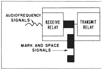
Figure 9. Tone-converter representation with the audio frequency
signal entering tone converter and the receive relay converting the audio
frequency signals to mark-and-space signals. |
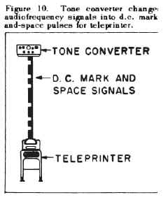
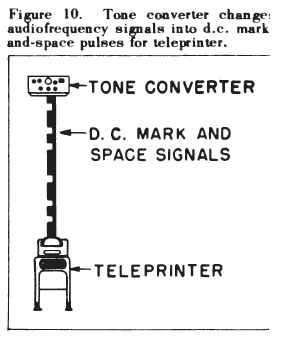
Figure 10. Tone converter changes audio frequency signals into d.c. mark
and-space pulses for teleprinter. |
-- |
-- |
"The Navy's Tone-Modulated Radio Teletype System"
By Joseph J. Fisher and Victor L. Kebler, Electronics Ship Division, Bureau of Ships
(General articles on the Navy's radio teletype system appeared in the Bureau of Ships Journal of
November 1955 and April 1956.)
The radio Teletype systems used by the U.S. Navy include two separate systems
- the carrier-frequency-shift system and the tone-modulated system. Both are found on
combatant ships, where they are integrated by use of several pieces of equipment in common. However, each
has a separate, specific purpose.
The tone-modulated system is designed for short-range communications, the carrier-frequency-shift
system for long range. This article concerns the tone-modulated system. The carrier-frequency-shift
system will be explained in later issues of the Journal.
Tone-Modulated System
The tone-modulated system is similar to standard AM radio. It can be used with any voice transmitter
and with any voice receiver.
Figure 1 is a complete diagram of the tone-modulated system used aboard ship. The tone terminal
equipment (tone converter) is the heart of the tone-modulated radio Teletype system. It is used for
both transmitting and receiving. Consequently, the switching control unit associated with the teleprinter
has a single "transmit-receive" position for tone-modulated operations.
A start impulse from the local teleprinter instantly and automatically switches the tone converter
to the transmit condition. While the tone converter is in the transmit condition, signals from the receiver
are blocked. The system cannot transmit and receive simultaneously.
When transmission stops, there is a slight delay before the converter automatically reverts to the
standby "receive" condition. The equipment will remain ready to receive until local transmission is
resumed.
The nature of the signal conversion that occurs in the tone converter and the nature of the subsequent signal modulation at the
transmitter are the fundamental points on which to base a good understanding of how the system operates.
The two basic circuits in the tone-modulated radio Teletype system are the transmit and receive
systems. A circuit common to both systems is the direct-current power supply to the Teletype panel that
furnishes the local "looping" current.
Figure 2 is a diagram of the transmit system showing the "mark" and "space" signals, the tone
signals equivalent to the mark-space signals, and the same tone signals modulated on a carrier wave. The
transmit circuit passes from the teleprinter through the tone-modulated transmit-receive position of
the switching control unit, through a channel in the Teletype panel, through the transmit side of the tone
converter, and thence to the transmitter.
Figure 3 shows the path of the receive circuit. When an incoming signal is received, it moves through
the receiver and through the receive side of the tone converter. From there it takes the same path through
the Teletype panel and the switching-control unit as that taken by the transmit signal. Then the signal
proceeds to the teleprinter where the mark and space signals are converted to a printed message.
Between the teleprinter and the tone converter, the circuits for transmitting and receiving are identical. The tone converter is the
point of divergence. It is the central component in both circuits.
The same message appears in three forms of signals both in transmitting and receiving. The Teletype
signal is a direct-current sequence of on-and-off, or mark and space pulses from the signal generator of
the teleprinter to the tone converter.
From the tone converter to the transmitter there is an alternating sequence of two different
audio frequency tones. From the transmitter out over the antenna, the signals are propagated by a tone-modulated
radio frequency carrier wave. This wave gives the system its name.
Three Types Illustrated
In figure 4 the three types of signals are illustrated:
- First, the direct-current sequence of mark and space pulses.
- Next the corresponding sequence of two different audio frequency tones—one tone at higher
frequency for "mark" and a different tone at lower frequency for "space."
- Finally, the modulated radio frequency carrier envelope with the audio
frequency tones impressed on it.
Thus a tone-modulated carrier wave is produced with its mark and space modulations corresponding to
the original direct-current mark and space pulses.
Figures 2 and 3 illustrate the transmitted and received signals passing through the equipment.
Figure 2 shows that when transmitting, the signal changes take place in the tone converter and in the
transmitter. Figure 3 shows that when receiving, the signal changes take place in the receiver and tone
converter.
Automatic Current Switch
In the tone converter (figure 5), the circuit has been automatically switched to the transmit side,
putting the receive relay out of operation. Inside the transmit relay, the on-and-off Teletype pulses control
a two-tone oscillator. A mark decreases the resistance and a space increases the resistance.
In this manner, the transmit side of the tone-converter changes the current and no-current pulses into
a corresponding sequence of two audio-tones, one tone during mark signals and a different tone during
space signals.
In other words, the tone converter changes the original direct-current Teletype signal to a form in which
it can be handled from then on by AM-voice radio equipment.
From the tone converter the audio signal goes to the transmitter (figure 6). The radiofrequency oscillator in the transmitter generates the
carrier wave. At the same time, the audio signal is amplified in the modulator stage.
Modulation of Carrier Wave
The final operation is modulation of the carrier wave, which is done by impressing the amplified audio
signal on the carrier wave. Thus a tone-modulated carrier wave with mark and space signals is produced
(figure 7).
The tone converter, by changing the original direct-current Teletype signal into
audio frequency tones, makes it possible to send the mark-and-space message through the air
by radio.
In the receiving circuit the arrangement is reversed.
From the antenna to the receiver the signal is a tone-modulated carrier wave (figure 8). From the
receiver to the tone converter it is a sequence of audio tones. And from the tone converter through the
Teletype panel and switching control to the teleprinter it is direct-current mark and space pulses (figures 9
and 10).
The receiver picks up the tone-modulated carrier wave with its mark and space modulations and
detects the signal, separating the audio tones from the carrier wave. The mark-and-space audio tones
then move on to the receive side of the tone converter.
The converter, which has now been automatically switched to the receive condition, converts the
sequence of audio tones into corresponding direct-current marks and spaces.
Thus the message is changed to a form that will actuate the selector magnet in the teleprinter.
A brief resume of the operation of the complete system follows:
In the transmit circuit, direct-current marks and spaces from the teleprinter pass through the
switching-control unit and Teletype panel to the transmit side of the tone
converter. There the direct-current pulses are changed to corresponding audio
frequency tones by the two-tone oscillator in the transmit relay.
Impressed on Wave
The audio tones go from the converter to the transmitter, where they are impressed on a
radio frequency wave to produce the tone-modulated carrier wave that gives the system
its name.
The same Teletype message occurs in three types of signals.
In the receive circuit the tone-modulated wave is picked up by the antenna and travels into the
receiver where the carrier wave is demodulated. The resulting audio mark-and-space tones enter the
receive side of the tone converter. Here the receive relay changes the tones back into their related direct-current marks and spaces. These
impulses are then routed through the Teletype panel and switching-control unit to the teleprinter.
This modulated system is the Navy's most widely used means for short-range (UHF) radio Teletype
communications afloat.