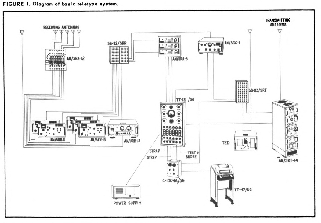
Figure 1. Diagram of basic teletype system.
The Navy's shipboard radio-teletype systems are designed to provide fast, reliable printed communications over a great range of distances. A complete shipboard teletypewriter installation includes a tone modulated system for short range communications and a carrier frequency shift system for long range communications (see figure 1)
Figure 1. Diagram of basic teletype system.
The tone modulated system is normally used with ultra-high frequency communication equipment. This system is similar in performance to the standard amplitude modulated (AM) radio broadcast system. It may also be used with any audio tone modulated transmitters and receivers which are not in the ultra-high frequency band.
The carrier frequency shift (CFS) system is intended for long range communications, generally in the low frequency, medium frequency, and high frequency bands. The operation of the carrier frequency shift system is somewhat similar to that of the standard frequency modulation (FM) radio broadcast system. Amplitude modulated transmitters and receivers must have special circuits and adapters for transmitting and receiving frequency shift teletype intelligence.
The tone modulated system and carrier frequency shift system are integrated to form one teletype system in shipboard communications.
Because of the wave propagation characteristics in the ultra high frequency band, the tone modulated
system is used only for short range or "line of sight" communications. Manmade and atmospheric
interference is seldom encountered in this band. Therefore, no special equipment is required, except that
which is normally used to communicate from ship to ship or from ship
to shore.
On the other hand, the frequency shift system used with the low to high frequency bands is the best way to send the rapidly keyed signals of the teletypewriter over long distances where fading and interference generally exist. Under good atmospheric conditions the frequency shift carrier wave will deliver a strong signal to a receiver at a great distance. However, bad weather and atmospheric interference are usually encountered in long distance transmissions, and this interference may weaken or cause the signal to fade entirely.
Atmospheric conditions may vary from one atmospheric layer to another, from day to night, and from
season to season. Since the changing atmospheric conditions can be a disturbing factor in long distance
communications, two methods of diversity reception have been adopted by the Navy. One method is
called space diversity and the other is called frequency diversity (see figures 2 and 3).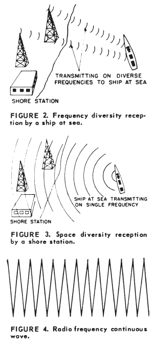
In space diversity reception, one signal is transmitted which is received on two receivers. Antennas for these receivers are separated at a distance greater than one wavelength. The outputs of the receivers are fed into two frequency shift converters and then into a comparator which selects the best signal for the teletypewriters.
In frequency diversity reception, two or more signals are transmitted on different frequencies. Two receivers, two converters, and a comparator are used as in space diversity. The receiving antennas need not be separated.
The advantages to be gained with the above methods of diversity reception result from the phenomenon that a single RF carrier usually does not fade simultaneously in areas separated by more than one wavelength, and that fading of carriers of different frequencies usually does not occur at the same point.
Frequency Diversity for Ships
Because of space limitations aboard ship, it is impractical to separate antennas far enough to
use space diversity reception in the low frequency, medium frequency and high frequency bands.
Therefore, the frequency diversity reception system has been adopted as standard for U. S. Navy vessels.
Shore stations use the space diversity system for receiving teletype signals because of the greater space available on shore for the spacing of antennas.
This arrangement is satisfactory because ships use a single transmitter for transmitting teletype signals to shore stations, and shore stations frequently use dual transmitters for sending the same signal simultaneously on different frequencies when communicating with ships.
Now that the basic facts concerning the two teletype systems have been presented, the reasons can be given as to why the tone modulated system is used in the ultra high frequency band and why the carrier frequency shift system is used in the low frequency, medium frequency, and high frequency bands.
First, consider a comparison between a keyed CW and audio tone modulated transmission. When a CW transmitter is keyed, the emission of the carrier wave is interrupted and represents dots and dashes in code. The amplitude of the CW carrier wave during emission is constant and, therefore, maximum power is radiated (see figures 4 and 5).
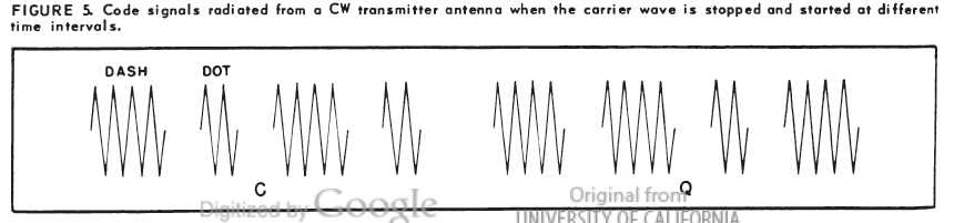
Figure 5. Code signals radiated from a CW transmitter antenna when the
carrier wave is stopped and started at different intervals
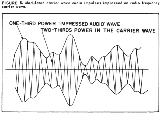
When a transmitter is tone modulated, the keying tone is impressed upon the carrier wave (see figures 6, 7, and 8).
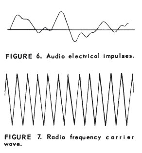 Figure 6. Audio electrical impulses Figure 7. Radio frequency carrier wave |
|
Carrier Wave Has More Power
In tone transmission, approximately two-thirds of the total power in the antenna circuit is in the
carrier wave. Only one-third of the power is in the audio tone modulated electrical impulses
(sidebands). As an example, assume that two transmitters have equal powers in the antenna circuits.
One is keyed and the other is tone modulated. The greater effectiveness will be apparent in the CW
transmission.
The carrier wave for frequency modulation (FM) or carrier frequency shift is similar to the CW carrier wave. That is, the amplitude of the carrier wave does not change when it is modulated. Modulation is provided by varying the frequency of the assigned carrier wave according to the audio intelligence being transmitted. The total power in the antenna circuit is never reduced by the varying frequency of the modulating signal (see figures 9 and 10).
The advantages and disadvantages of the two teletype systems can now be compared: The tone modulated system (audio electrical impulses representing "mark" and "space" signals impressed on the carrier wave) has the characteristics noted in table 1. The carrier frequency shift system has the characteristics shown in table 2.
| TABLE 1 Tone Modulated System |
|
| ADVANTAGES | DISADVANTAGES |
|
|
| TABLE 2 Carrier Frequency Shift System |
|
| ADVANTAGES | DISADVANTAGES |
|
|
Normally the carrier frequency shift system is confined to the low frequency, medium frequency, and high frequency bands. If steps were taken to increase the shift of the mark-space signals, it would be possible to use the carrier frequency shift system in the very-high frequency and ultra-high frequency bands. This change would not be economical because numerous changes would be required in the existing transmitters and receivers. Increasing the mark-space signal shift would also have the undesirable effect of increasing the band width of each teletype channel and reducing the number of channels in the very high frequency and ultra-high bands.
For information and training purposes, a series of teletype training films has been prepared.
SERIES I (NOW AVAILABLE)
FN-7467A-The TT-47/UG Teletype writer, Operation and Principles.
FN-7467B-The TT-47/UG Teletypewriter, Installation and Performance Tests.
FN-7467C-The TT-47/UG Teletypewriter, Preventive Maintenance.
SERIES II (AVAILABLE JANUARY 1956)
MN-8099A-Radio Teletype System Afloat, General Principles of Operation.
MN-8099B-Radio Teletype System Afloat, Tone Modulated System.
MN-8099C-Radio Teletype System Afloat, Carrier Frequency Shift Transmitting System.
MN-8900D-Radio Teletype System Afloat, Carrier Frequency Shift Receiving System.
SERIES III (NOW AVAILABLE)
MN-9237A-Mechanical Operation of the TT-47/UG Teletypewriter Keyboard, Transmitting Mechanism.
MN-9237B-Mechanical Operation of the TT-47/UG Teletypewriter Keyboard, Automatic Type Selection Mechanism.
MN-9237C-Mechanical Operation of the TT-47/UG Teletypewriter Keyboard, Type Box Positioning
Mechanism.
MN-9237D-Mechanical Operation of the TT-47/UG Teletypewriter Keyboard, Function Mechanism.