|
|
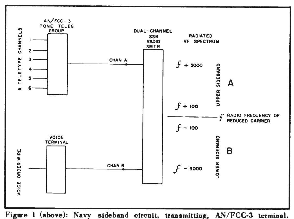 Figure 1: Navy sideband circuit, transmitting, AN/FCC-3 terminal |
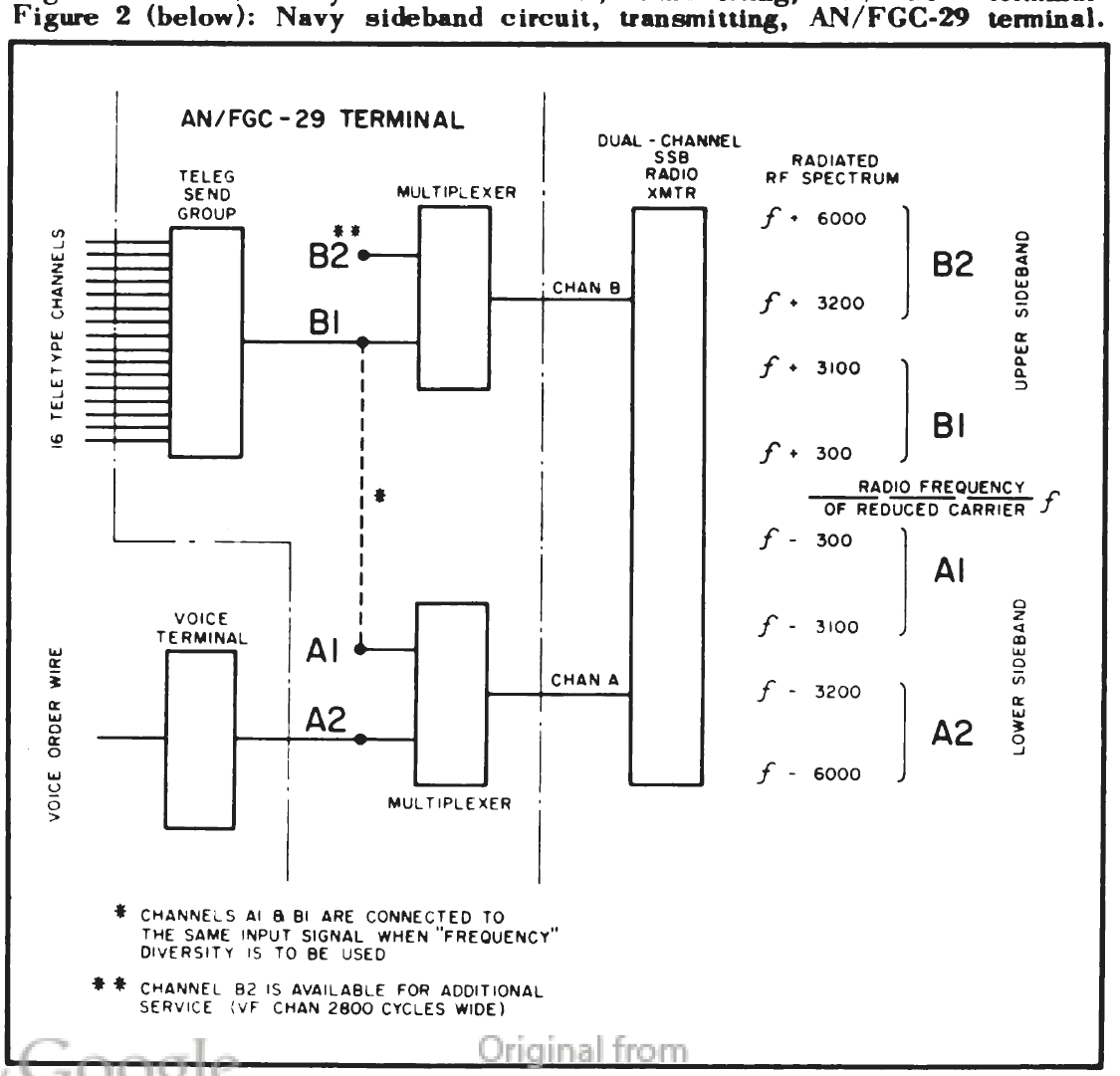 Figure 2: Navy sideband circuit, transmitting, AN/FGC-29 terminal |
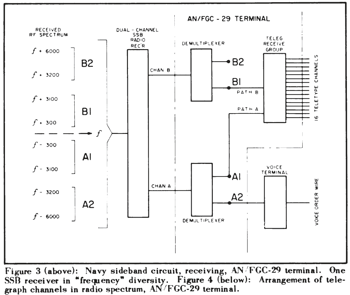 Figure 3: Navy sideband circuit, receiving, AN/FGC-29 terminal. One SSB receiver in "frequency" diversity. |
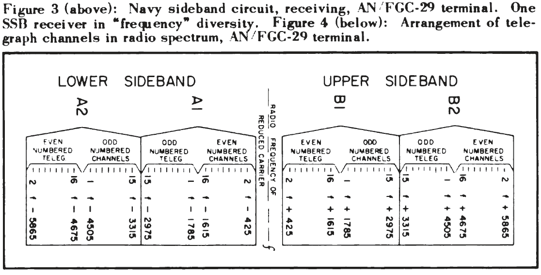 Figure 4 : Arrangement of telegraph channels in radio spectrum, AN/FGC-29 terminal. |
The Navy is engaged in raising the telegraph channel capacity of its long-range point-to-point single-sideband radio circuits by using 16-channel AN/FGC-29 telegraph terminals to replace the older 6-channel arrangements of AN/FCC-3 tone telegraph equipment.
While the primary purpose of installing the AN/FGC-29 terminal is to increase the number of available telegraph channels in long-range radio circuits (the AN/FGC-29 provides sixteen 100 w.p.m. teletype channels within a frequency spectrum 2800 cycles wide), the multiplexers used in this terminal would also make it possible to add radio telephone or facsimile facilities over the same radio path. Some of the capabilities of the AN/FGC-29 terminal are illustrated here by diagram to show possible channel utilization of this versatile equipment.
The point-to-point radio circuits which now connect the Navy's major communication stations ashore are dual-channel single-sideband reduced-carrier systems in which the upper and lower sidebands of the transmitted radio signal (designated sideband A and sideband B) carry separate intelligence (figure 1).
The AN/FGC-29 telegraph terminal contains multiplexer and de-multiplexer units (TD-97/FGT-2 and TD-98/FGR-3) which separate each radio sideband into two parts (figure 2), thereby providing a total of four voice-frequency (VF) channels, each 2800 cycles wide, over the dual-channel single-sideband radio system.
Two of these VF channels normally will be used for multi-channel telegraph (teletypewriter) service and one VF channel will be used for a voice order wire, leaving one 2800 cycle VF channel for telephone or facsimile communications if proper telephone or facsimile terminal equipment is provided.
Figures 1 and 2 depict the transmitting end of the Navy sideband circuits. At the receiving end, the systems are similar except that diversity combining methods are used to overcome the "drop out" effects of radio fading.
The receiving portion of the AN/FGC-29 terminal contains two groups of telegraph channel units which will accept the same 16-channel telegraph intelligence from two sources (for example, from radio receiver number one and radio receiver number two, using two spaced antennas for "space" diversity) and will provide diversity combining of the two signals. Combining is accomplished by the ratio-squared method.
In addition to "space" diversity radio reception, which has been used for many years in long-distance radio communications to reduce the effect of fading, the AN/FGC-29 terminal, by providing split sidebands, allows the use of "frequency" diversity with only one receiving antenna and one single-sideband radio receiver. In this system the same multi-channel telegraph signal is transmitted simultaneously over two of the partial sidebands (assumed in figure 3 to be A1 and B1, although another two of the partial sidebands A1, A2, B1, or B2 could be used).
Radio fading is reduced because the fading patterns of two radio signals differing in frequency by at least 600 or 700 cycles are essentially uncorrelated; that is, they do not fade at the same instant.
At the receiving end of this system the two telegraph receive groups of the AN/FGC-29 terminal are fed "path A" signals and "path B" signals from the partial sidebands (A1 and B1 in figure 3) for diversity combining. The combining action in the AN/FGC-29 terminal takes place in exactly the same way, whether the signals are derived from a single radio receiver (receiving two partial sideband signals in frequency diversity) or from two separate radio receivers operating in space diversity.
It may be of interest to know how the 16 channels of teletypewriter signals are arranged in the radio-frequency spectrum when the output of the AN/FGC-29 telegraph send group is applied to one or more of the partial sidebands A1, B1, A2, or B2. Figure 4 shows this arrangement, assuming for purposes of illustration that the 16-channel signal has been applied to all four partial sidebands.
In practice the multi-channel telegraph signal will be applied to only two of the partial sidebands, normally A1 and B1. It will be seen from figure 4 that certain telegraph channels will not be separated far enough in frequency for good diversity action if the multi-channel signal is applied to the two halves of the same sideband (Al and A2) or (B1 and B2). It will also be seen that the overall channel width occupied in the radiofrequency spectrum depends on which of the partial sidebands are modulated.