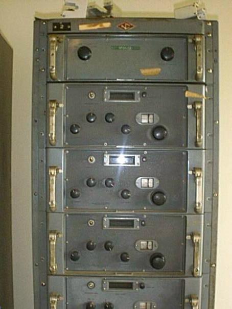
Photo thanks to K1KGG
National Company logo at top of rack
If you have one of these monsters, or any pieces of one, please send me e-mail - I have acquired almost all the modules and cables to assemble a system and would like to acquire some additional pieces and information. I also have some spare modules to trade. I'd also like to correspond with other FRR-24, FRR-37, or FRR-10 owners as I start assembling and testing mine. I'd really like to hear from anyone who has photos or knows how & where these systems were used by the US Navy.
The FRR-24 manual says
BASIC SIMILARITIES AND DIFFERENCES IN THE AN/FRR-24 RADIO RECEIVING SET
AND THE MODEL RCP DIVERSITY RADIO RECEIVING EQUIPMENT. [RCP
info page]
(1) SIMILARITIES.-Basically the AN/FRR-24 Radio Receiving Set performs the same function as
that of its predecessor the Model RCP Diversity Radio Receiver except that in addition it provides
a means of receiving frequency shift telegraphy signals.
(2) DIFFERENCES.-The AN/FRR-24 is entirely different in its electrical design and mechanical
construction from that of the previous unit. The AN/FRR-24 is intended for operation in the frequency
range of 2.0 to 32.0 megacycles whereas the Model RCP operates in the frequency range of
3.0 to 24.0 megacycles.
Photo thanks to K1KGG |
National Company logo at top of rack |
 System
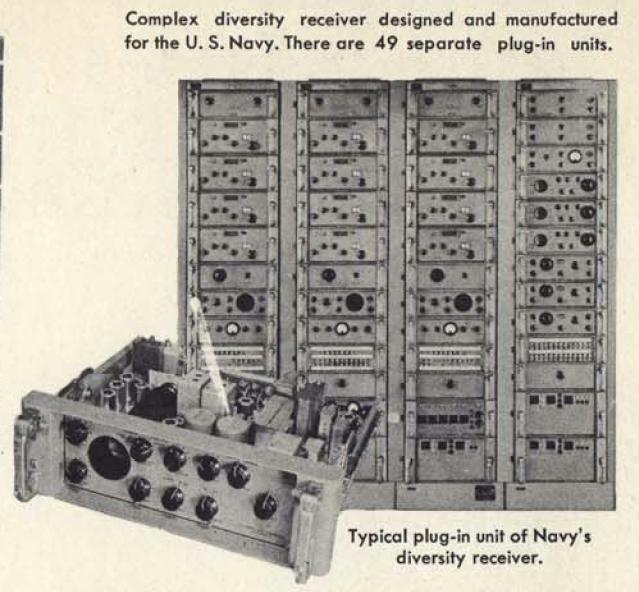
 The AN/FRR-24 (pictured at right) is a triple diversity dual-conversion HF (2-32 Mc.) receiver
made by the National Co. (Malden, Mass.) around 1950. It was primarily
designed for shore station teletype circuits..
The
complete manual is NAVSHIPS 91580 dated April 1952. manual
pdf (100MB)
Procured under contract NObsr-39402 (30 June 1947) for $60,260 ea.
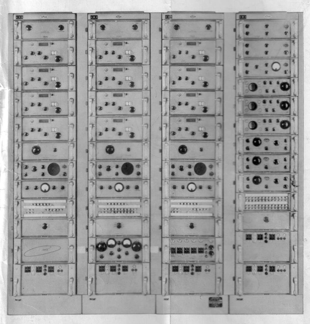
The AN/FRR-24 consists of 4 racks weighing a total of 3,121 lbs. Racks 1, 2, and 3 contain essentially identical receiver assemblies. Each receiver rack has 4 RF tuning modules (2-4mc, 4-8mc, 8-16mc, 16-32mc). Each receiver rack also has a detector/AF unit for monitoring purposes. IF selectivity can be set from 18kc to 125cps bandwidth (a Vectron LC filter was used for 250cps and Vectron crystal filter for 125cps). Rack 4 contains 3 detectors and 3 FSK converters plus signal comparators for triple diversity reception. Rack 4 also has 3 keyers to drive TTY signals over landlines as audio FSK signals. See below for more info on the racks and all the modules. Each receiver rack has 88 vacuum tubes, with 420 total for the entire system.
N4LQ's AN/FRR-24 single receiver rack - AM - video
N4LQ's AN/FRR-24 single receiver rack - CW - video
 System
The AN/FRR-37 is almost identical to the FRR-24 except with dual-diversity. The maintenance handbook (available from www.w7fg.com) is NAVSHIPS 91896.3 and dated March 1953. The complete manual is NAVSHIPS 91896. - MIL-HBK-161 photo thanks to www.jamminpower.com
Procured under contract NObsr-57388 (21 May 1952) for $41,245 ea.
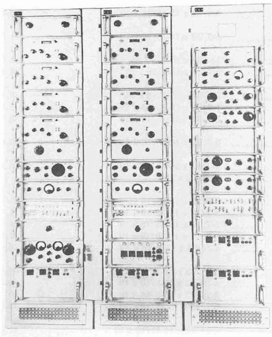
The FRR-37 is a 3-rack dual-diversity version of the FRR-24 and is composed of racks 2, 3, and 4 - there is no rack 1. Rack 4 has 2 of various detector, converter, and keyer modules where the FRR-24 has 3 of them.
The FRR-37 rack (CY-1377/FRR-10) is about 12-14" deeper than the FRR-24 rack (CY-860/FRR-24), making cable access much easier. Almost all the FRR-37 modules have an A suffix and are FRR-24 units, as in SB-142A/FRR-24. However some modules are slightly different, with different unit numbers:
 System
 The FRR-10 manual is NAVSHIPS 92144 dated 2 February 1954. The manual says it is basically the same as the predecessor receivers FRR-24 and FRR-37 except that the FRR-10 provides dual-diversity AM, SSB, and ISB (simultaneous LSB & USB) reception and does not provide FSK or CW capability. The shipping weight of a complete FRR-10 system is 3740 lbs, but the uncrated weight is a mere 2362 lbs. The FRR-10 has 253 tubes and consumes about 1450 watts.
Procured under contract number NObsr-52433 (23 May 1951) for $43,100 ea.
The FRR-10 is a 3-rack configuration containing 2 receiver racks for dual-diversity reception of AM, SSB, and ISB. It does not include FSK or CW capability. The receivers have the same 4 RF units and first converter as FRR-24 and FRR-37, but the 50kc IF amp, filters, detectors, AFC, and diversity control are all different and have /FRR-10 suffixes. IF selectivity is 8, 12, or 16kc plus USB and LSB filters. There is a motor-driven AFC control in Rack 3. Almost all the FRR-10 modules that are common to the FRR-24 have a B suffix, such AM-450B/FRR-24. However, for some reason the SB-142A/FRR-24 Control Panel is an exception.
The FRR-10 configuration uses the same rack cabinet (CY-1377/FRR-10) as the FRR-37.
Please send e-mail if you have any info or photos on any of these units, AN/FRR-10, AN/FRR-24, or AN/FRR-37.
This is the only unit I have seen with a "B" model number - AM/450B/FRR-24
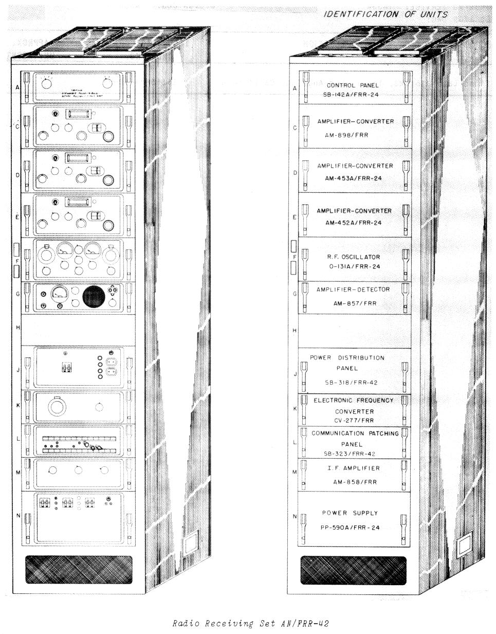
The AN/FRR-42 is a 4-32 mc single channel, single-rack system similar to rack #2 of AN/FRR-24. External equipment is necessary for FSK detection.
The AN/FRR-43 is a 4-32 mc three channel, three-rack system similar to AN/FRR-24 but without the 4th rack. External equipment is necessary for diversity combining and FSK detection.
Manufactured by National - contract NObsr-57572 (19 June 1952)
AN/FRR-42 - $18,025 ea. with equipment spares
AN/FRR-43 - $54,085 ea. with equipment spares
Manual is NAVSHIPS 91891
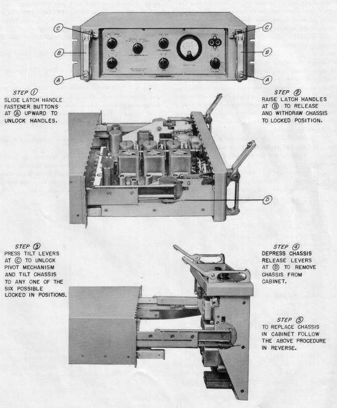
The dual conversion receiver design is reasonably straightforward but extremely well-engineered and ruggedly-constructed - each module is a 19" rack-mounted case with a slide-out, tilting chassis. Each RF tuning module chassis is a massive aluminum casting with silver-plated tuning caps, etc.. Signal and well-filtered power connections are made internally through a plug/jack block between chassis and case. Each case (except for the power supplies) is fully enclosed with no external air access - blowers at the base of each rack force cooling air up the rack mount channels and around the sides of each module. There are openings from the air channels to the interior of a just few modules, the power supplies and CV-127 RTTY converters - all the other modules are fully enclosed.
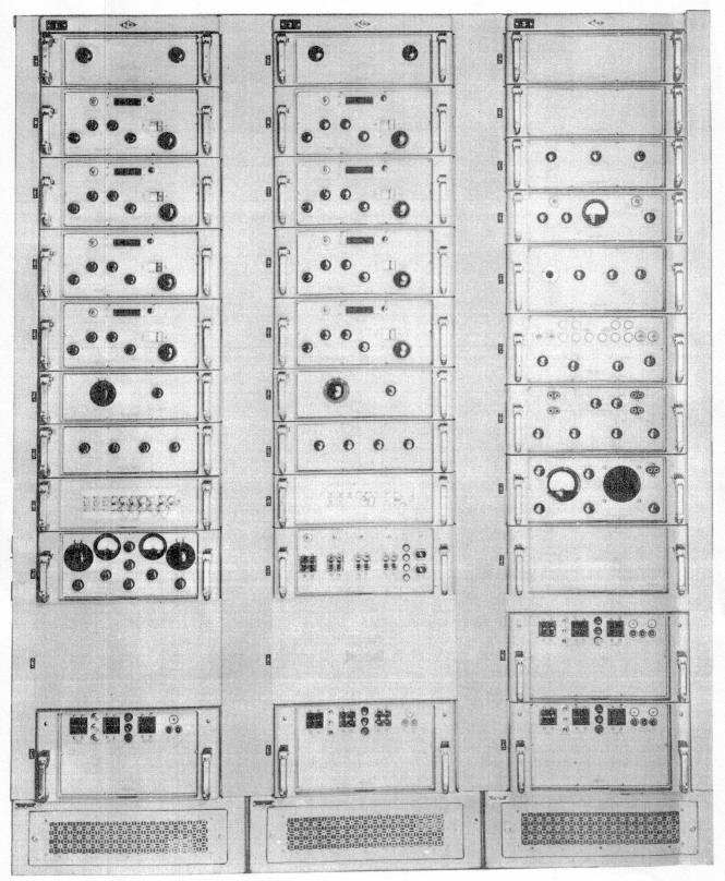
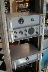
Complete FRR-24 system as shown in manual |
 FRR-24 Rack 2 - upper Bandswitch + 4 RF units |
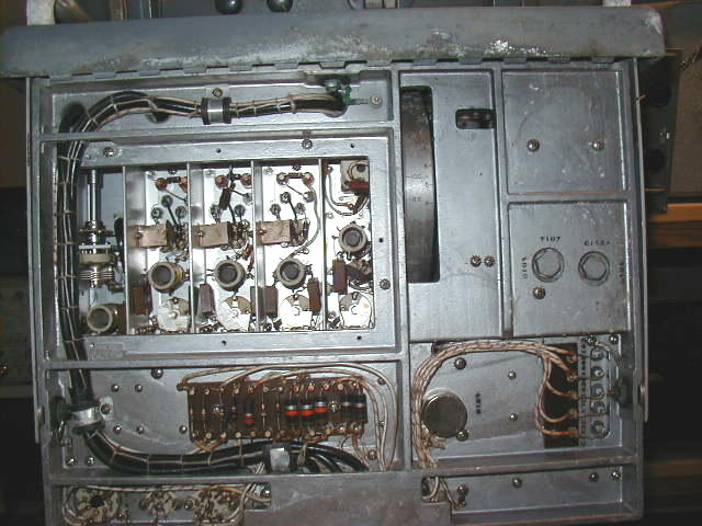
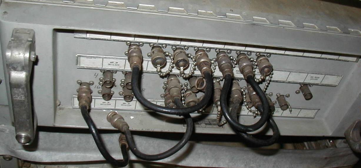
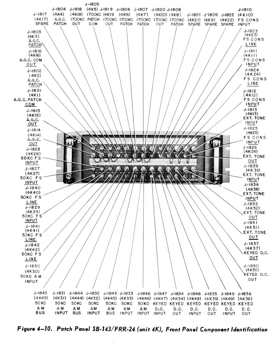
 FRR-24 Rack 2 - lower 2nd mixer, detector/monitor, IF amp, patch panel, bandpass filters, xtal osc, power supply |
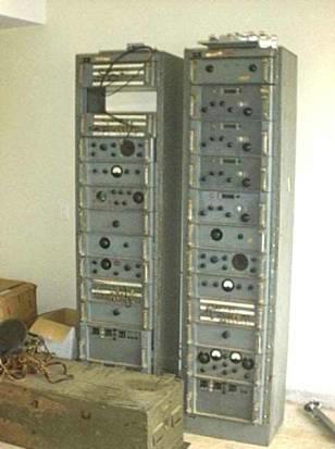 FRR-24 racks left rack - misc storage Rack 2 - receiver unit #2 |
| The photos above are from an eBay listing several years ago - If you are the current owner of this or any other FRR-24, please let me know | |||
 MY FRR-24 WORKS! with 3 RF units installed so far 11/06/2007 |
 Click Here for photos of my FRR-24 and FRR-37 systems undergoing re-assembly and restoration |
-- | -- |
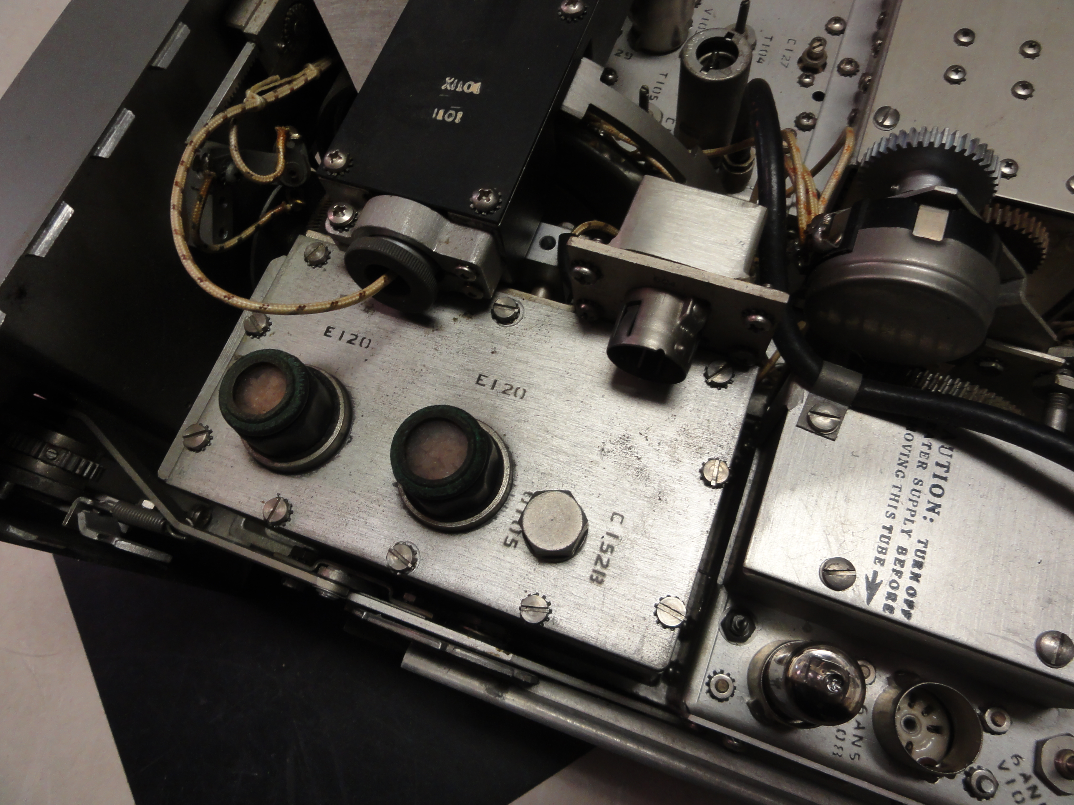
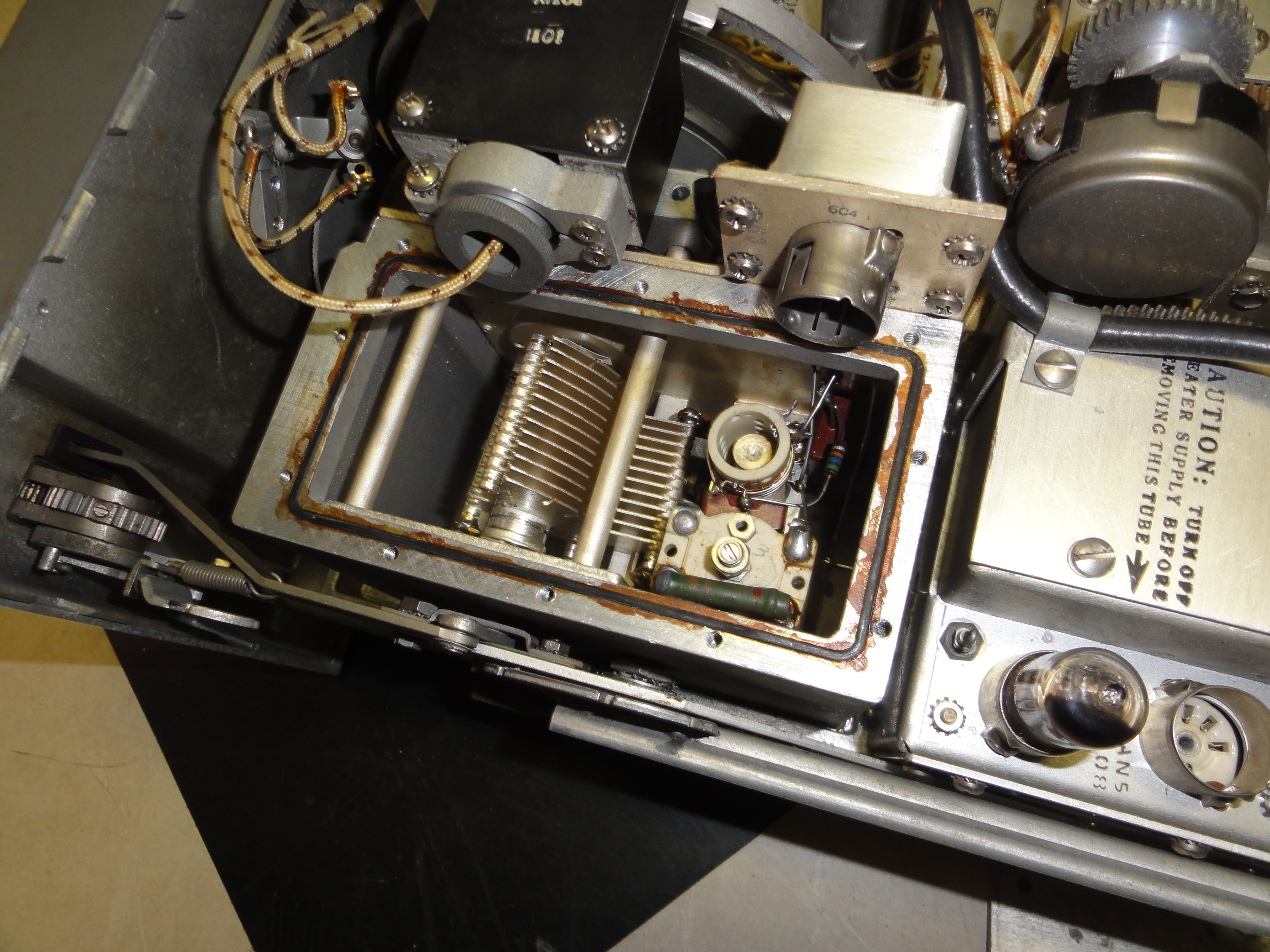
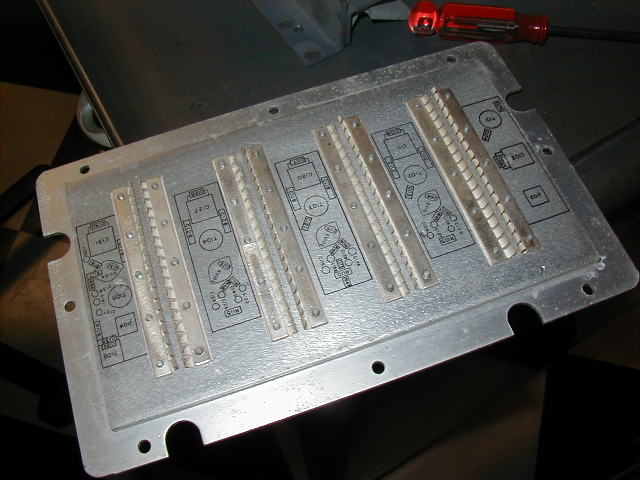
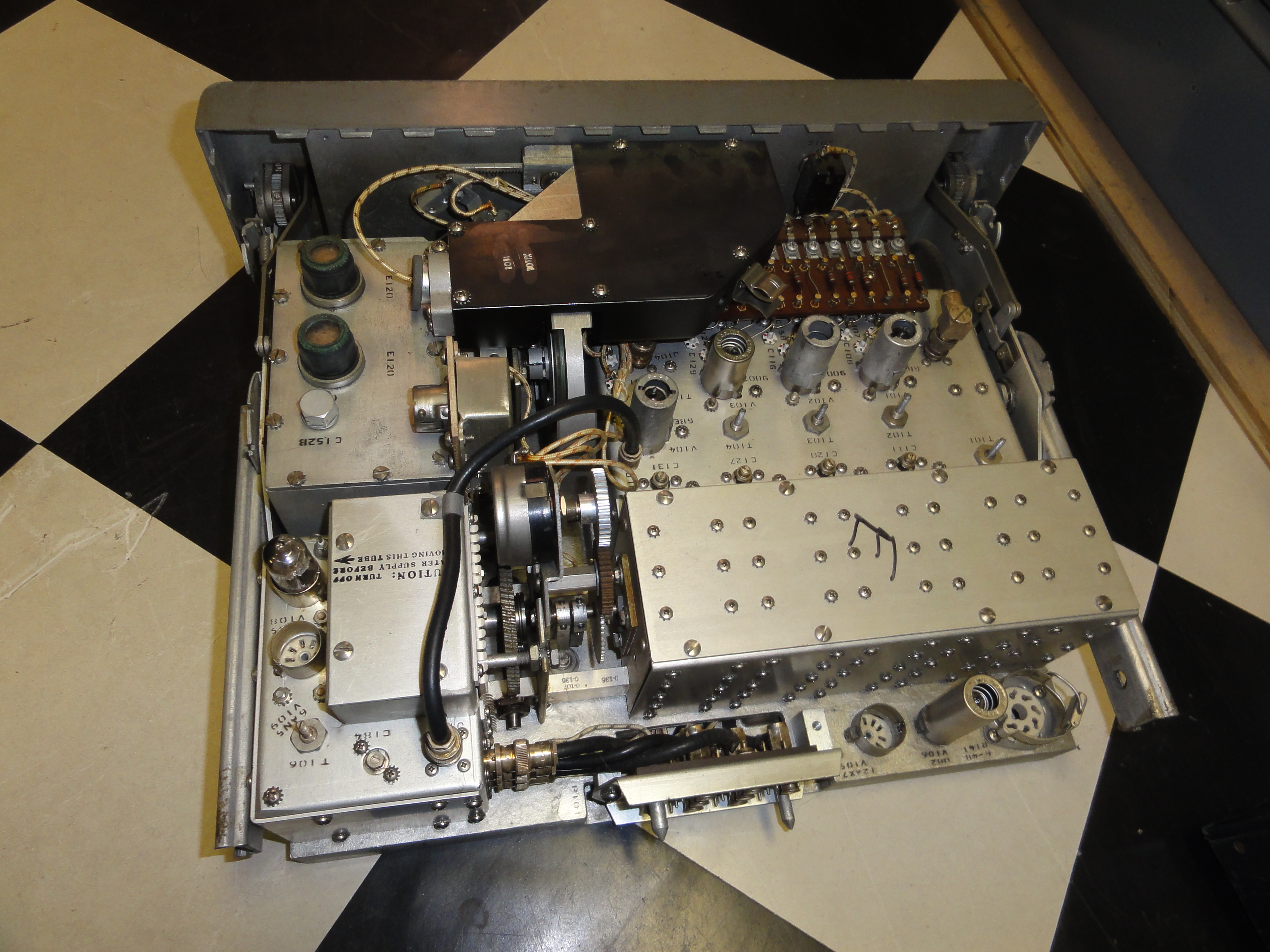 Typical Module Construction - AM-453 RF tuning module underside- massive aluminum casting for chassis |
 Local Oscillator |
 Local Oscillator |
 Local Oscillator |
 Typical Module Construction - AM-453 RF tuning module underside- massive aluminum casting for chassis |
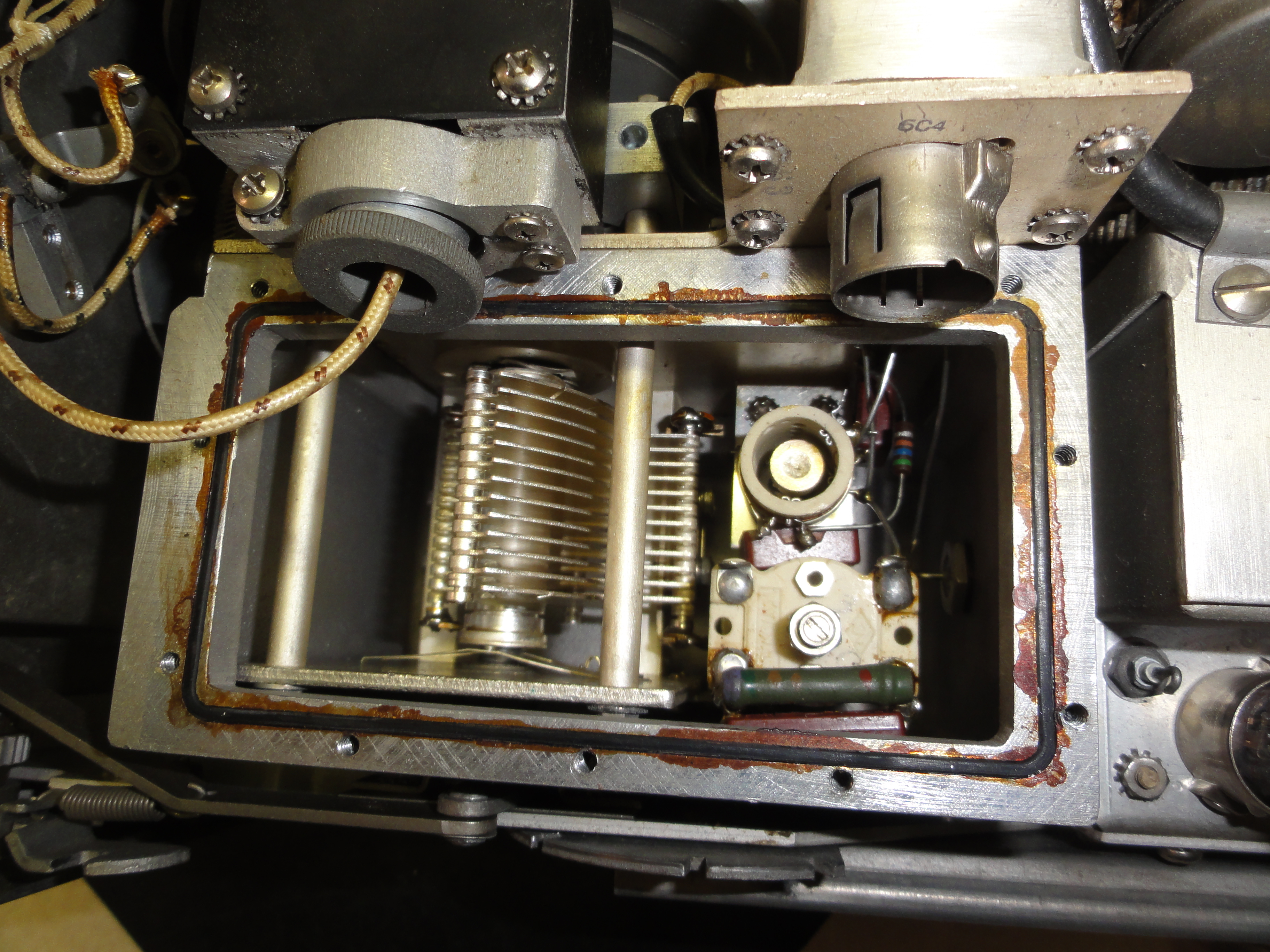
 AM-453 close-up of antenna, 3 RF, and mixer stages with thorough shielding |
 AM-453 close-up - cover for RF stages - grounding fingers plus thick silver-plated cover. |
-- |
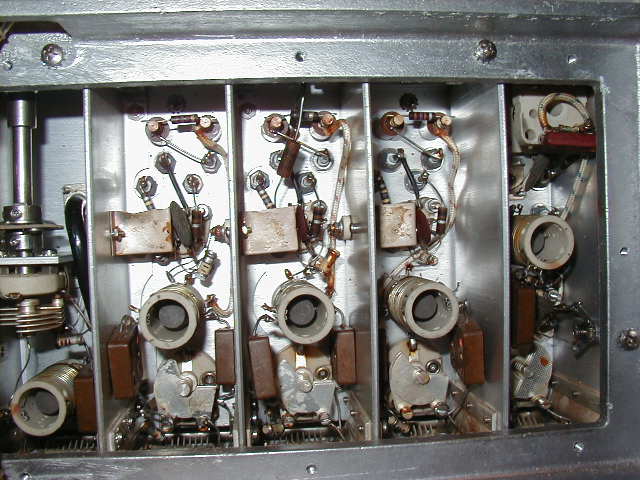
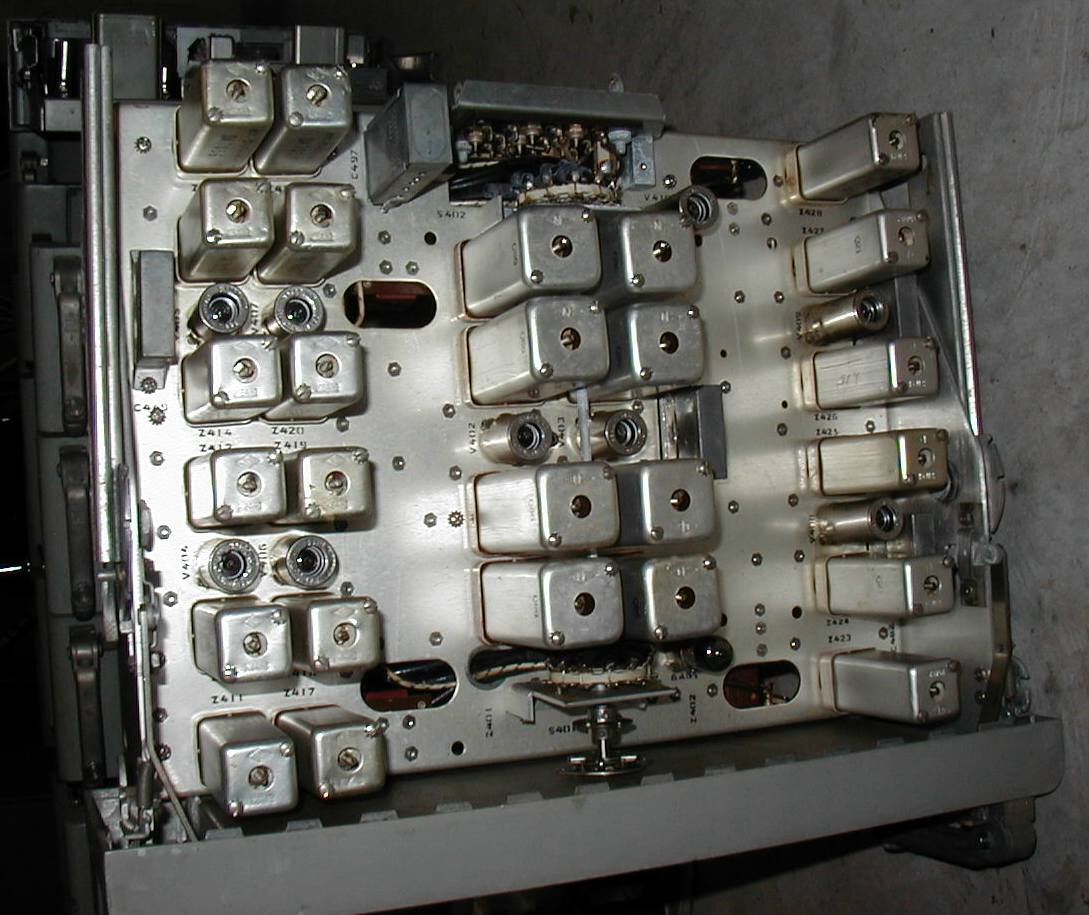
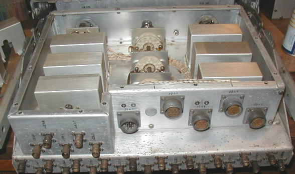 Typical Module Construction - SB-142 "bandswitch" layout with individual shield boxes for each switch section |
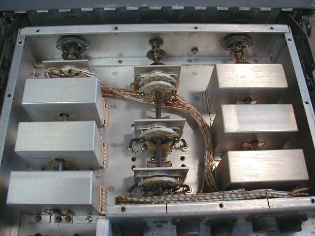 SB-142 energizes a selected RF unit and routes HF oscillator and AGC lines to/from it |
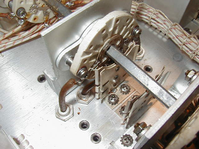 SB-142 close-up showing spring grounding clips for shields - coax is fed from rear connector under chassis and into shielded box. |
 SB-142 close up showing additional spring grounding fingers on shield |
There are 420 tubes in a complete AN/FRR-24. There are 88 tubes within each of the three receiver assemblies. Most RF and IF amp stages use type 9003 pentodes. For illustration, the main signal path of one receiver assembly (configured for AM reception) has over 20 tubes in the signal chain and is organized as follows -
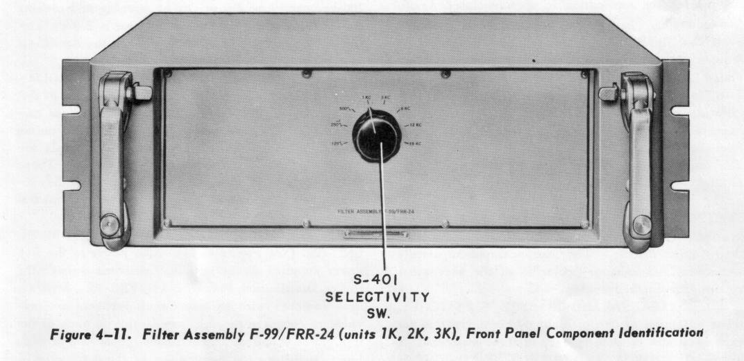
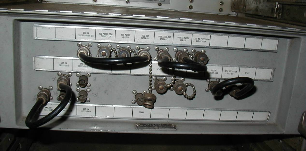
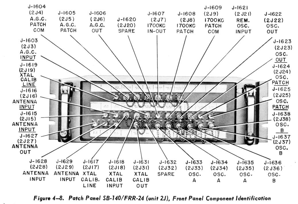
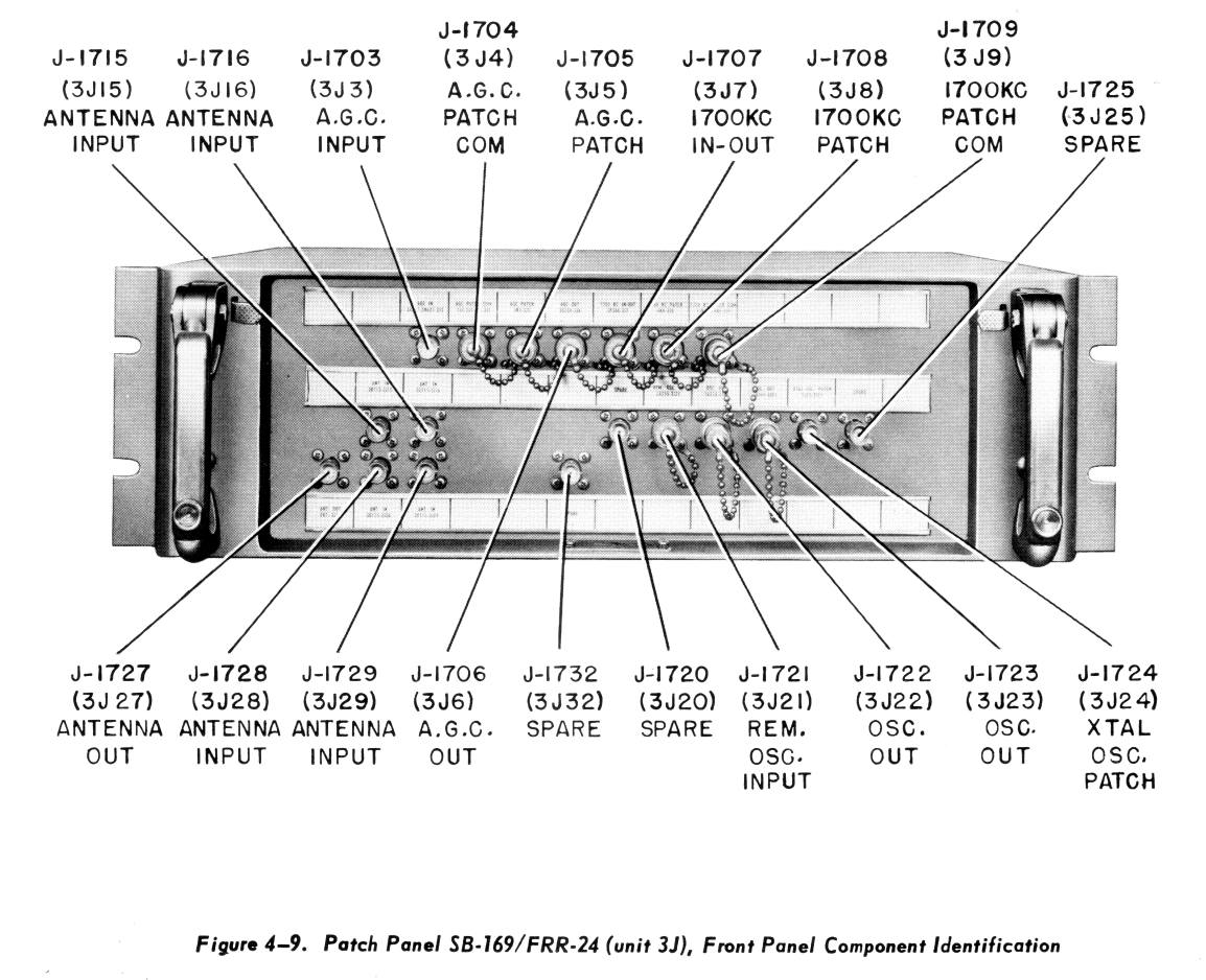
The AN/FRR-24 is exceptionally versatile. A set of patch panels allows the system to operate in different configurations. The Operator's manual lists 14 modes of operation and then says "these are but a few of the possible combinations of units". For example the system can operate as 3 separate receivers. Or it can combine outputs in dual or triple diversity mode. The three racks can be separately tuned or one of the receivers can be used as a master oscillator for the others, or a separate crystal oscillator can drive one or more receivers. There are also multiple ways to couple AGC voltage among the units.
Links -