1965 US Navy Shipboard Electronic Equipment - NAVPERS 10794-B
CHAPTER 3 RADIO EQUIPMENT
The radio equipment described and illustrated in this chapter is selected as representative of the many models and types of radio
transmitters, receivers, and auxiliary equipment used in the fleet today. No attempt is made to cover all equipment in use, and, in
consonance with the security classification of this text, any discussion of classified equipment is avoided.
TRANSMITTERS AND TRANSCEIVERS
Modern shipboard transmitters must be of rugged construction for long service life. They must be capable of
transmitting over a wide range of frequencies and distances. Moreover, they must provide various modes of operation. Transmitters that meet
these requirements are quite complex and, because of the limited space available for radio installations in naval vessels, are of compact
construction.
One method of obtaining equipment compactness is to combine a transmitter and a receiver into one unit called a transceiver. A transceiver
used part of the same electronic circuitry for both transmitting and receiving, hence cannot transmit and receive simultaneously. A
transmitter-receiver, however, is a separate transmitter and receiver mounted in the same rack or cabinet. The same antenna may be utilized
for the transmitter-receiver arrangement, but the capability for independent operation of the equipment still exists. Both terms are
commonly used when discussing radio equipment.
In the following descriptions of specific equipment capabilities, the term "short range" (or "distance") means a measurement less than 200
miles; "medium range" is between 200 and 1500 miles; and "long range" exceeds 1500 miles. These values are approximations, because the
range of a given equipment varies considerably according to terrain, atmospheric
conditions, frequencies, and time of day, month, and year.
LF, MF, AND HF TRANSMITTERS
Transmitters operating in the low-, medium-, and
high-frequency bands of the frequency spectrum are used chiefly for communication at medium and long ranges. Some transmitters in these bands, however, are designed for short-range communication. In most
instances, short-range transmitters have a lower output power than those designed for communication at medium and long ranges.
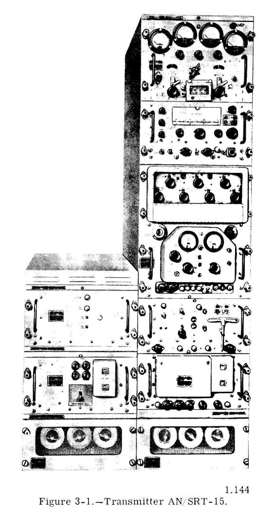
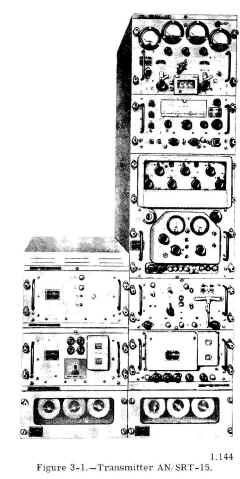
Transmitters AN/SRT-14, -15, and -16
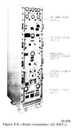
Transmitting sets AN/SRT-14, -15, and -16 are a series of shipboard transmitters designed for medium-
and long-range communications. The AN/SRT-14 is the basic transmitter in the series, with a power output of 100 watts. By adding a power
booster to the basic transmitter, it becomes the AN/SRT-15 (fig. 3-1). The AN/SRT-15 has an optional output power of either 100 or 500
watts. Transmitter set AN; SRT-16 consists of two AN/SRT-14 equipments plus the booster, furnishing two entirely independent transmitting
channels of 100-watt output, with the 500-watt booster available for use with either channel when desired.
All three transmitters cover the frequency range 0.3 to 26
mc, and may be used for CW, radiotelephone, radioteletype, and facsimile
transmissions. The 500-watt output power, however, is available only when the AN/SRT-15 or the AN/SRT-16 is operating in the frequency
range of 2 to 26 mc at frequencies below 2 mc, output is limited to 100 watts. |
 |
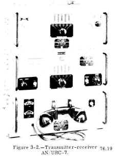
Transmitter-Receiver AN, URC-7
The AN/URC-7 is an amplitude-modulated transmitter-receiver for short-distance radio-telephone communication. Both transmitter and receiver have six pretuned crystal-controlled channels in the frequency range 2000 to 7000
kc. The transmitter has an output power of 25 watts. The transmitter, receiver, and the modulator-power supply are contained in a single
cabinet (fig. 3-2).
The AN/URC-7 is used principally in service craft and auxiliary-type ships, such as tugs, transports, tankers, and ships of the amphibious force |
 |
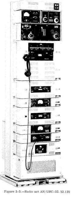
Transceiver AN/URC-32
Radio transceiver AN/URC-32 (fig. 3-3) is a manually operated radio communication equipment for operation in the 2- to 30-mc (high
frequency) range. With a power output of 500 watts, this transceiver is capable of transmitting signals over long distances. It is
designed for single-sideband transmission and reception on upper sideband, lower sideband, or the two independent sidebands simultaneously,
with separate a-f and i-f channels for each sideband. In addition to SSB operation, provisions are included for compatible a-m (carrier
plus upper sideband), CW, or frequency shift keying (fsk). The fsk mode of operation is used for sending radioteletype (RATT) and
facsimile (FAX) signals.
The frequency range of 2 to 30 mc is covered in four bands. The desired operating
frequency is selected in 1-kc increments on a direct-reading frequency counter. Frequency accuracy and stability are controlled by a
self-contained frequency standard. Provisions also are made for using an external frequency standard.
Because of its versatility and power, the AN/URC-32 is installed on most Navy ships having a requirement for communicating at long
distances. |
 |
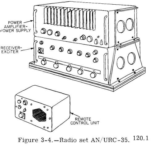
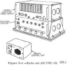
Transceiver AN/URC-35
Radio set AN/URC-35, shown in figure 3-4, is a recently developed, single-sideband transceiver. It is a compact equipment that operates
over a frequency range of 2 to 30 mc while providing three modes of operation: upper sideband, lower sideband, and amplitude modulation
(compatible). For single-sideband operation, the transmitter power output is 100 watts; for amplitude-modulated operation, the available
carrier power is 25 watts.
Although capable of transmitting CW and fsk signals, the AN/URC-35 is used chiefly for voice communications over short and medium
distances. It is replacing the TCS series transmitter-receiver (discussed later) aboard Navy ships. |
 |
Transmitter AN/WRT-1
The AN/ WRT-1 (fig. 3-5) is a shipboard transmitter
designed for operation in the frequency range 300 to 1500 kc. This
equipment can transmit CW, fsk, and voice signals, but it has no SSB
capability. When used for CW and fsk transmissions, the transmitter ha: a
power output of 500 watts. Voice operation, however, reduces the available
power to approximately 125 watts.
Because of operating in the medium frequencies with a
substantial power output, the AN/WRT-1 lends itself well for communicating
over long distances during the hours of darkness. Its range is reduced to
medium distances during daylight hours. |
 |
Transmitter AN/WRT-2
Radio transmitter AN/WRT-2 (not illustrated) is similar
in size and appearance to the AN/WRT-1. It covers the frequency spectrum
between 2 and 30 mc, and has an average power output of 500 watts for CW,
fsk, and compatible a-m modes of operation. When operating as a
single-sideband transmitter, it produces 1000 watts. An additional feature
of the AN/ WRT-2 is that it provides independent sideband operation. This
mode of operation permits simultaneous transmission of both sidebands,
each one carrying separate intelligence.
As indicated by its operating frequencies and power
outputs, the AN/WRT-2 is used for long-range communications. |
no photo |
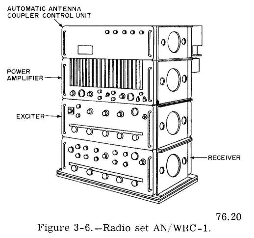
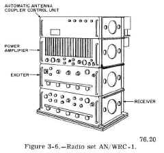
Transmitter-Receiver AN/WRC-1
Another radio set that covers the frequency range 2 to 30 mc is the AN/WRC-1
transmitter-receiver, illustrated in figure 3-6. It has a maximum power output of 100 watts, and is capable of transmission and reception on upper sideband, lower sideband, continuous wave,
amplitude modulation, frequency shift keying, and independent sideband modes of operation.
An outstanding feature of the AN/WRC-1 is that it has an automatic antenna tuning system. This system automatically tunes the antenna to
the transmitter's output frequency, thereby assuring maximum transfer of power at all times.
Because the AN/WRC-1 is a recently developed equipment, only a limited number of sets presently are installed aboard
ships They are being procured for installation through the fleet, however. |
 |
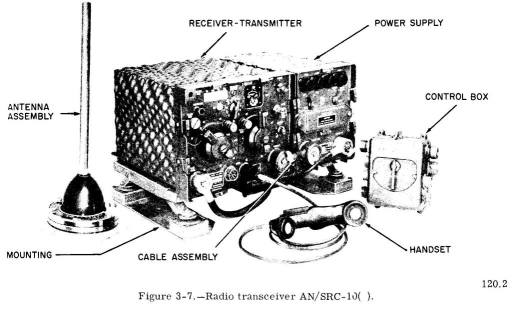
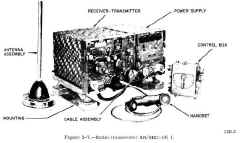
Transceiver AN/SRC-10( )
Although originally designed as an Army equipment radio transceiver AN/SRC-10( ) (fig. 3-7) is installed aboard Navy ships for
short distance amphibious communication in the fre quency range 2 to 27.9
mc. Its only mode of operation is radiotelephone, which is
delivered : selectable power output of either 2 or 16 watts. When supplemented with certain
accessories the AN/SRC-10( ) becomes a portable radio set for use ashore and in boats.
One major difference between this set and equipment discussed previously is that it the frequency-modulation (f-m) principle
for voice transmission. The others, when used for radiotelephone, are amplitude-modulated. |
 |
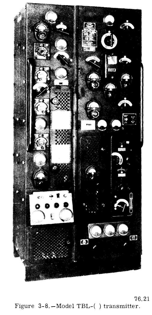
Transmitter Model TBL-( )
The TBL-( ) transmitter, illustrated in fig 3-8, has been used extensively for many
years. It has a power output of 200 watts on CW and 50 watts on voice mode. In addition, it provides a modulated continuous-wave (MCW) mode of operation at an output of 100 watts. The
MCW mode is similar to regular CW, except that an audio tone is used to modulate the carrier. Because this mode is less efficient than
regular CW, it seldom is used. The TBL-( ) operates in two frequency ranges. The low-frequency side of the transmitter covers the range
175 to 600 kc; the high side, from 2 to 18 mc. Both sides cannot be keyed simultaneously. To shift from one frequency range to the other,
however, is simply a matter of throwing a switch.
Because the original design of the TBL-( ) made no provision for radiotelephone operation, a separate speech amplifier (not illustrated)
must be used with the transmitter when transmitting voice signals. The most recent improvement to the transmitter is field change AN/WRA-1,
which gives it the single-sideband capability. |
 |
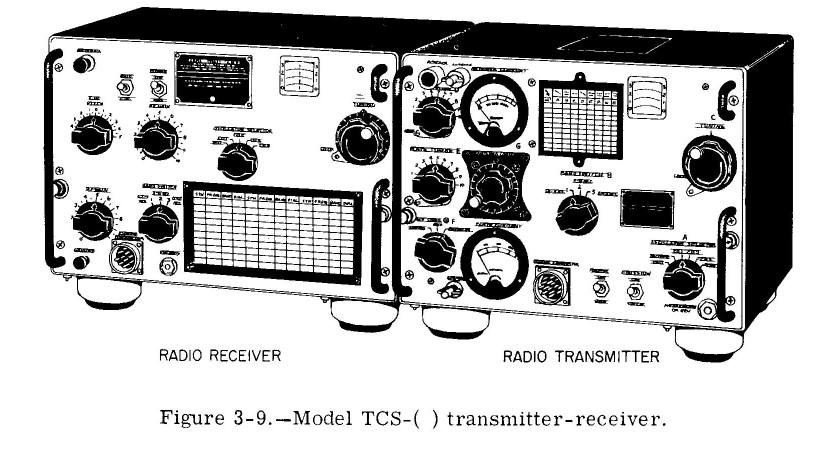
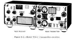
Transmitter-Receiver Model TCS-( )
The model TCS-( ), shown in figure 3-9, is a small transmitter-receiver that has been
in use for many years for short-range communications. It has an output power of 10 watts for radiotelephone and 25 watts for CW. The TCS-(
) has a frequency range of 1.5 to 12 mc. Its frequency-determining section may be either crystal-controlled or a continuously variable
oscillator, whichever is more desirable. Transmitter and receiver use the same antenna, which is switched from receiver
to transmitter by a relay when the transmitter is keyed. Although it is being replaced the
AN/URC-35, the TCS-( ) still is used aboard ships of all types. |
 |
VHF TRANSMITTERS
Except for special applications, equipment in the VHF range no longer are used extensively by the Navy. Most tactical voice
communications now are conducted in the UHF band. Limited shipboard installations of VHF equipments are retained, however, for
emergency communications and for communication with allied forces that have not yet
converted to UHF equipments.
Transmissions in the VHF range normally are restricted to line-of-sight distances (less than 30 miles). Under certain atmosphere
conditions, they have been received at considerably longer distances-500 miles or
more. Obviously, this sometimes unpredictable behavior of VHF signals jeopardizes the
security of tactical communications. It is for this reason that the Navy shifted to the UHF
band.
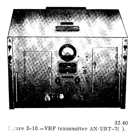
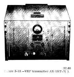
Transmitter AN/URT-7( )
The AN/URT-7( ) (fig. 3-10) is a crystal controlled VHF transmitter that operates : the frequency range 115 to 156
mc. Although mountings
for four crystals are provided, permitting rapid selection of any one of four frequencies, the transmitter must be returned
each time the frequency is changed. With a power output of 30 watts, this equipment provides
two modes of operation: radiotelephone and MCW. |
 |
Transceivers AN/SRC-11( ) and -12( )
Except for the frequencies covered, radio transmitting and receiving sets
AN/SRC-11( ) and AN/SRC-12( ) ) are identical to the AN/SRC-10(
) discussed under high-frequency transmitters. All three sets are f-m transceivers used for amphibious communication They afford a total
frequency coverage of 20 to 54.9 mc, with the AN/SRC-11( ) operating in the frequency range 27 to 38.9
mc, and the AN/SRC-12( ) covering
between 38 and 54.9 mc. |
no photo |
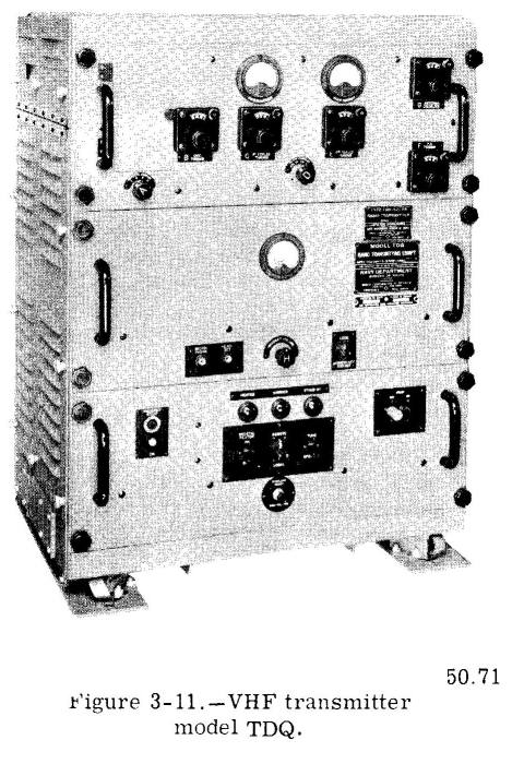
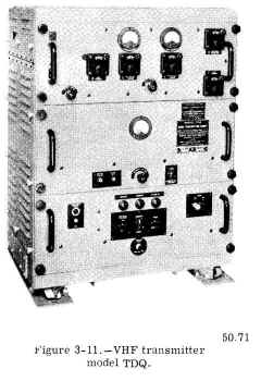
Transmitter Model TDQ
The model TDQ transmitter (fig. 3-11) although being replaced by the newer AN/URT-7,
still is installed aboard all types of ships. Like the AN/URT-7, it is crystal-controlled and operates in the VHF range between 115 and 156
mc. Modes of operation are radiotelephone and MCW. Power output is 45 watts. |
 |
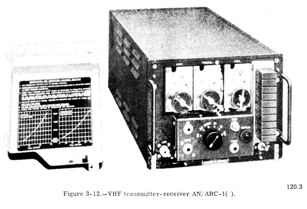
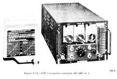
Transmitter-Receiver AN/ARC-1( )
Radio transmitter-receiver AN/ARC-1( ). illustrated in figure 3-12, is a low-power (8
watts) VHF equipment designed for installation in aircraft. For many years this set has been used aboard ship for surface-to-air and
surface-to-surface communication. It provides two-way radiotelephone operation on any one of ten
pre-tuned, crystal-controlled channels in the frequency range 100 to 156 mc. Channel selection is accomplished by means of a remote control unit (not illustrated). |
 |
UHF TRANSMITTERS
Most UHF radio transmitters (and receivers) used by the Navy operate in the 225- to 400mc frequency range. Actually, this range of
frequencies covers portions of both the VHF band and the UHF band. For convenience, however, radio sets operating within this frequency
range are considered to be UHF equipment. The effective distance range of UHF normally is limited to line-of-sight distances, making it ideally suited for low-power tactical voice
communications.
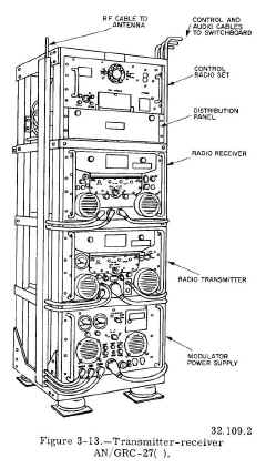
Transmitter-Receiver AN/GRC-27( )
The AN/GRC-27( ), shown in figure 3-13, is a UHF transmitter-receiver set covering frequencies from 225 to 400
mc. This equipment is used
for radiotelephone and MCW communications from ship-to-ship, ship-to-shore, or with aircraft. The AN/GRC-27( ) is installed principally in
carriers and antisubmarine warfare ships, whose primary missions involve the
control of aircraft.
The transmitter has a power output of 100 watts. It has three crystal-controlled oscillators, using a total of 38 crystals. These crystals,
located within the transmitter, do not require handling by the operator. From the combination and multiplication of these 38 crystal
frequencies are produced 1750 frequencies spaced at 100-kc intervals throughout the transmitter's frequency range. Any 10 of these 1750
frequencies can be preset manually with selector switch dials. Of the 10 preset frequencies, one then can be selected automatically by a
telephone-type dial. The automatic selection can be made either locally at the transmitter or from a remote unit at other locations, such as CIC and the bridge.
Only 2 to 7 seconds are required to shift automatically from one channel to another in any of the 10 preset channels.
The receiver also operates on any of the 1750 channels It is a triple-conversion superheterodyne and has crystal oscillators using 38
crystals in a system separate from but similar to that used in the transmitter. Here, again, automatic shifting of channels is done in
about 2 to - 7 seconds.
Both transmitter and receiver use the same antenna A relay switches the antenna from one to the other. |
 |
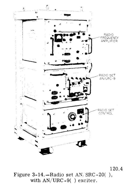
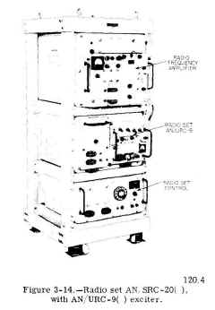
Radio Sets AN/URC-9( ), AN/SRC-20( ), 1 and AN/SRC-21( )
Radio set AN/URC-9( ) is a UHF transmitter-receiver that provides facilities for a-m radiotelephone communication in the frequency range
225 to 399.9 mc. The equipment is crystal-controlled and produces 1750 frequencies at 100-kc intervals within its frequency range.
Although it is capable of operating on only one frequency at a time, any 20 of the 1750 available frequencies can be : preset for immediate selection from remote
positions Channel selection requires a maximum of 8 seconds. This set has a power output of approximately 20 watts.
When modified by the addition of certain units, e AN/URC-9( ) is redesignated either AN/ SRC-20( ), illustrated in figure 3-14, or AN/SRC-21( ). These modified sets can be connected to similar sets so that received signals are retransmitted automatically. This feature is
useful when a ship (or aircraft) is serving a relay station between two stations that cannot communicate with each other directly. The
difference between the AN/SRC-20( ) and the AN/SRC-21( ) is that the AN/SRC-20( ) has a power amplifier unit that increases the 20-watt
power output from the AN/URC-9( ) to a 100-watt output. |
 |
Transmitter Model TED-( )
The model TED-( ) is a crystal-controlled, single-channel, UHF transmitter that operates in the frequency range 225 to 400
mc. Except for
operating in a different frequency range and having a lower output power, this transmitter
is identical to the VHF transmitter AN/URT-7 described earlier and illustrated in figure 3-10. The TED-( ) has an output power of 15 watts.
An r-f power amplifier (AM-1365/URT), designed for use with this transmitter, currently is being installed in the fleet. The amplifier
boosts the output power to 100 watts. |
no photo |
PORTABLE AND PACK RADIO EQUIPMENT
Because portable and pack radio sets must be lightweight, compact, and self-contained,
they usually are powered by battery or hand generator, have low output power, and are either transceivers or transmitter-receivers. Navy ships carry a variety of these radio sets for emergency and amphibious communications. The numbers and types of this equipment vary according to the individual ship.
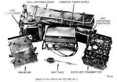
Transmitter-Receiver AN/GRC-9( )
Radio set AN/GRC-9( ) is a low-power radio transmitter and receiver. (See fig. 3-15.) It can be used in either vehicular or ground
installations. It is carried aboard ship for use by landing parties for communicating with the ship.
The AN/GRC-9( ) receives and transmits CW, MCW, and a- m radiotelephone signals in the 2- to 12-mc frequency range. Provision is made for
six crystal-controlled channels.
Master oscillator tuning is also available for any frequency within the band.
For different kinds of installations, the radio set can be operated with batteries, dynamotors, gasoline-driven generators, or hand-driven
generators.
The output power of the transmitter varies somewhat, depending on the type of power supply used. When powered by the hand generator,
the output is approximately 10 watts CW and 4 watts on phone. Reliable communication range is usually about 30 miles for CW and 10 miles
for phone.
The receiver and transmitter are contained in a metal case that has a tight-fitting removable cover. These components are dirtproofed
and waterproofed for complete protection while transporting the equipment and when operating under extremely adverse weather conditions. |
 |
Transceivers AN/PRC-8, -9( ), -10( )
The AN/PRC-8, -9( ), and -10( ) series of portable radio sets provide voice communications for amphibious operations. These are man-pack
sets, and, except for their operating frequencies and the components that determine these frequencies, they are similar electrically and
mechanically. They are f-m equipments that are designed for use with their shipboard counterparts AN/SRC-10, -11, and -12, described
earlier in this chapter.
Total frequency coverage of the three sets is 20 to 54.9 mc. The AN/PRC-8 covers frequencies between 20 and 27.9 mc. the AN/ PRC-9( ),
between 27.0 and 38.9 mc; and the AN/PRC-10( ), between 38 and 54.9 mc. With an output power of approximately 1 watt, these portable sets
have an effective range of approximately 5 miles.
Figure 3-16 illustrates radio set AN/PRC-41 (discussed in the next topic), but the AN/PRC-8, -9( ), and -10( ) series closely resemble this
set when they are assembled for man-pack operation. |
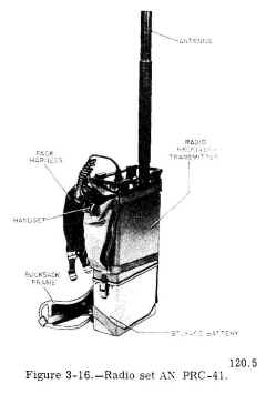 |
Transceiver AN/PRC-41
Radio set AN/PRC-41 is a watertight, lightweight, portable UHF equipment that may be operated on any of 1750 channels, spaced 100 kc apart
in the 225- to 399.9-mc range. Its only mode of operation is a-m voice, which it supplies at an average output power of 3 watts. Although
designed principally for man-pack operation, the set also may be used for fixed station and vehicular operation -when complemented by certain accessories. When not in use, the
equipment is disassembled and stowed a compartmentalized aluminum transit case similar to an ordinary suitcase. |
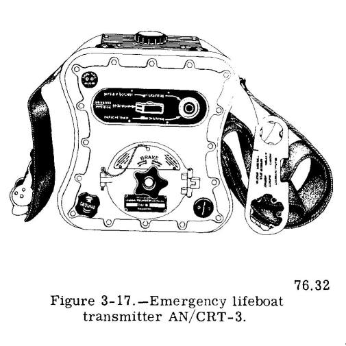
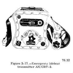
Transmitter AN/CRT-3
Radio transmitter AN/CRT-3, popularly known as the "Gibson girl," is a rugged - emergency transmitter carried aboard ships and aircraft for
use in lifeboats and liferafts is shown in figure 3-17. No receiving equipment is included.
The transmitter operates on the international distress frequency (500 kc) and the survival
raft communication frequency (8364 kc). The complete radio transmitter, including the power supply, is contained in an aluminum cabinet that is airtight and waterproof. The
cabinet is shaped to fit between the operator's legs, and has a strap for securing it in the operating position.
The only operating controls are a three-position selector switch and a pushbutton telegraph key. A handcrank screws into a socket in the top
of the cabinet. The generator, automatic keying, and automatic frequency changing are all operated by turning the handcrank. While the
handcrank is being turned, the set automatically transmits the distress signal SOS in Morse code. The code sequence consists of six groups
of SOS followed by a 20-second dash, transmitted alternately on 500 kc and 8364 kc. The frequency automatically changes every 50 seconds.
These signals are intended for reception by two groups of stations, each having distinct rescue functions.
Direction-finding stations cooperating in long-range rescue operations normally make use of 8364 kc, whereas aircraft or ships locally engaged in
search and rescue missions make use of the 500-kc signals. Besides the automatic feature, the transmitter can be keyed manually, on 500 kc only, by means of the pushbutton telegraph key.
Additional items (not shown) packaged with the transmitter include the antenna, a box kite and balloons for supporting the antenna, hydrogen-generating chemicals for inflating the balloons, and a signal lamp that can be powered by the handcrank generator.
The equipment floats, and is painted brilliant orange-yellow to provide greatest visibility against dark backgrounds. |
 |
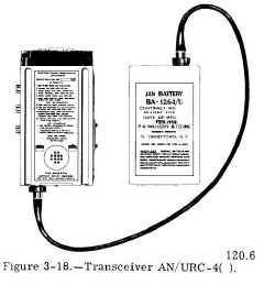
Transceiver AN/URC-4( )
The AN/URC-4( ) (fig. 3-18) is a compact, portable transceiver. It is small enough that the combined transmitter and receiver can be
grasped and held with one hand. This unit is connected by a short cable to its battery case, which is approximately the size of the
transceiver.
T he complete set is intended to be carried in a special vest-type garment worn by airmen while they are on flight missions. It also may be
dropped by parachute to personnel in distress. But, the principal use of this set in the Navy is for extremely short-distance distress
communication between lifeboats (or liferafts) and searching rescue aircraft or ships.
This transceiver is a crystal-controlled equipment that provides voice and MCW transmissions over two frequency ranges within the VHF band.
Frequencies covered are between 120 and 130 mc and between 240 and 260 mc. The operating frequency of the set is determined by a single
crystal, which must be changed each time the frequency is changed. The set is
pre-tuned, and can be operated by anyone familiar with its purpose. |
 |
Transceivers AN/URC-16( ), -17( ), -18( )
Except for the difference in power supplies and accessories, the AN/URC-16( ), -17( ), -18( )
series of portable radio sets essentially are the same as the shipboard-installed AN/ SRC-10, -11, -12 series described earlier in this
chapter. |
no photo |
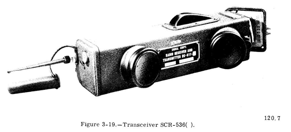
Transceiver SCR-536( )
Radio transceiver SCR-536( ), shown in Figure 3-19, is a low-power, battery-operated transceiver used for voice communication over very
short distances (1 to 3 miles). The equipment is crystal-controlled, and it operates on a
preset frequency in the range of 3.5 to 6 megacycles. The operating frequency is varied by changing the crystal and certain other
frequency-determining components within the set. Usually, these changes are made by a technician.
The set is energized by extending the telescopic antenna. When thus energized, it functions as a receiver. Applying pressure
on the press-to-talk switch (located on the side of the set) shifts the equipment from a receive condition to a transmit condition. The set
remains in the transmit condition as long as the switch is held depressed.
Weighing only 5-1/2 pounds, this portable set comes equipped with a carrying strap. Often the set is used as a means of communication by
personnel moving about on foot, as while on shore patrol. Also, it serves as a means of communication between small boats and their parent
ships. |
 |
RECEIVERS
Modern Navy radio receivers are easy to operate and maintain. They are capable of receiving several types of signals and can be tuned
accurately over a wide range of frequencies. Because they are not required to
produce or handle large currents and voltages, their size is relatively small when compared to the size of most transmitters.
Unlike the receiving units of the transceivers described earlier, the radio receivers discussed in this section are separate equipments
that are capable of independent operation.
VLF, LF, MF, AND HF RECEIVERS
Most radio receivers operating in the VLF, LF, MF, and HF bands of the frequency spectrum are of the continuous tuning type. They are
tunable to any frequency within their frequency range, and they usually cover this range in several tuning bands. Switching from one band
to another changes the receiver's frequency-determining components, permitting more accurate tuning than is possible if the entire
frequency range were covered by a single set of components.
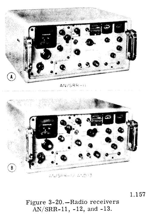
Radio Receivers AN/SRR-11, -12, -13
Radio receivers AN /SRR-11. -12, and -13 (fig. 3-20) are modern communication receivers used in all types of Navy vessels. They are
companion receivers to the previously described transmitters AN, /SRT-14, -15, and -16. Frequencies covered are between 14 kc and 32 mc.
The frequency range of each receiver is divided into five bands. The frequency range of the AN/SRR-11 is from 14 to 600 kc: the AN/ SRR-12,
from 0.25 to 8 mc; and that of the AN / SRR-13 is from 2 to 32 mc. The frequency range of AN/SRR-12 includes the standard broadcast band,
and overlaps part of the frequencies covered by the other models. It is unlikely that you will encounter this model in the fleet, because
the Navy procured very few AN/SRR-12 receivers.
The AN/SRR-11 receiver is used for guarding low and medium frequencies, such as the international distress frequency (500 kc). Its most
general use, however, is for receiving the VLF and LF transmissions of the fleet broadcasts. This receiver can be used for CW, MCW, and
frequency shift RATT and FAX reception.
The AN/SRR-13 covers all of the HF band. In addition to receiving CW, MCW, RATT, and FAX, it is an exceptionally good radiotelephone
receiver.
Both the AN/SRR-11 and -13 models are double superheterodyne receivers. A
crystal-controlled calibrator in each receiver provides crystal checkpoints for ensuring that the frequency dial is calibrated properly with the frequency-determining components of the receiver. The
checkpoints, which are spread uniformly over the tuning range of the receivers, occur at 10-kc intervals for the AN/ SRR-11 and at 200-kc
intervals for AN/SRR-13.
The frequency to which the receiver is tuned appears projected on a translucent screen (tuning dial) located at the upper left of the front
panel. On the AN/SRR-11 the dial is calibrated in kilocycles; on the AN/SRR-13, in megacycles. |
 |
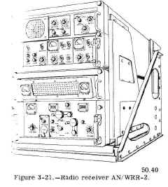
Radio Receiver AN/WRR-2
One of the latest shipboard radio receivers for the medium- and high-frequency bands is the AN/WRR-2. (See fig. 3-21.) This modern
receiver is of the triple-conversion superheterodyne type, and it covers the frequency
range from 2 to 32 mc. Although intended chiefly for the reception of SSB transmissions, it can be used also to receive CW, MCW, voice, facsimile, and frequency shift RATT.
In order to meet strict frequency tolerances, special features provide extremely accurate
tuning and a high degree of stability over long periods of operation. The frequency to which the receiver is tuned is indicated on
counter-type dials that resemble the mileage counter on an automobile dashboard.
Simultaneous use can be made of both upper and lower-sideband channels for receiving two
types of intelligence. Both single sideband and conventional a-m signals cannot be received at the same time, however. |
 |
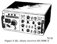
Radio Receiver AN/WRR-3
Radio receiver AN/WRR-3 (fig. 3-22) is a dual-conversion superheterodyne receiver for craft and submarine installations. It CW, MCW, and frequency
shift keying. This receiver covers the frequency range of 14 to 600 kilocycles in five bands. They
are
- Band 1, 14 to 30 kc.
- Band 2, 30 to 63 kc.
- Band 3, 63 to 133 kc.
- Band 4, 133 to 283 kc.
- Band 5, 283 to 600 kc.
The frequency to which the receiver is tuned is read directly on drum-type dials.
An internal calibration circuit provides calibration points at each 10-kc tuning point within the tuning range of the receiver.
|
 |
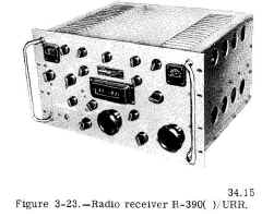
Radio Receiver R-390( )/URR
Operating in the frequency range 500 kc to 32 mc, radio receiver R-390( )/URR (fig. 3-23) is a modern, high-performance, exceptionally
stable receiver for both shipboard and shore station use. It can receive CW, MCW, a-m radiotelephone, and frequency shift radioteletype and
facsimile signals. When used in conjunction with single-sideband converter CV591( )/URR, it also is an excellent SSB receiver.
The receiver is a superheterodyne type, with multiple-frequency conversion. In the frequency range from 500 kc to 8 mc, it uses triple
conversion. Double conversion is used in the range from 8 to 32 mc.
The tuning knob turns a complex arrangement of gears and shafts to indicate the frequency to which the receiver is tuned on a very accurate
counter-type dial. The dial is calibrated in kilocycles, and the frequency reading accuracy of this tuning dial permits use of the
receiver as an accurate frequency meter. |
 |
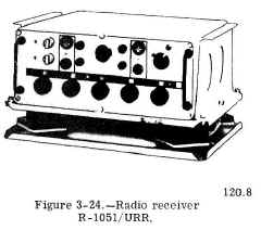
Radio Receiver R-1051/URR
The R-1051/URR (fig. 3-24) is one of the newest radio receivers. It is a
versatile superheterodyne receiver capable of receiving any type of radio signal in the frequency range 2 to 30 mc. It can be used as an
independent receiver. Or, in conjunction with a transmitter, it can be used to form a transmitter-receiver combination, such as
radio set AN/WRC-1 described already.
Basically a crystal-controlled equipment, the R-1051/URR employs a digital tuning scheme for automatic tuning to any one of 56,000
operating channels. An additional fine tuning control provides continuous tuning throughout the receiver's frequency range.
This receiver is designated as standard equipment for use aboard all ships. Although presently available in limited numbers only, it is
being procured for distribution throughout the fleet. |
 |
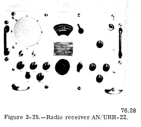
Radio Receiver AN/URR-22
Radio receiver AN/URR-22 (fig. 3-25) is designed chiefly for reception of voice transmissions on the standard broadcast and international
shortwave broadcast bands. Additionally, it can be used as an emergency communication receiver for CW and MCW signals.
It is a superheterodyne receiver covering the frequency range of 540 kc to 18.6 mc in four frequency bands.
This receiver (and the similar AN/URR-44) is intended as a replacement for the older model RBO entertainment receiver (discussed later). |
 |
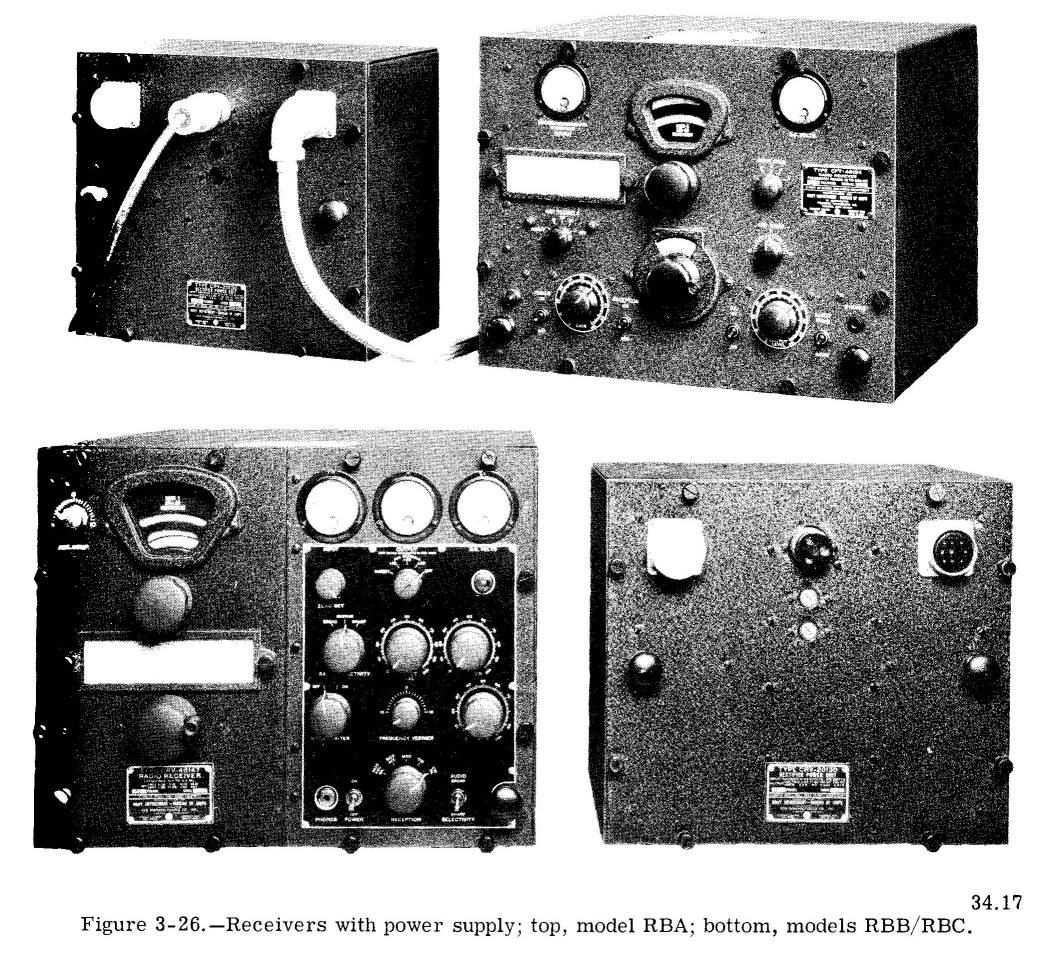
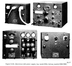
Radio Receivers RBA, RBB, and RBC
The RBA, RBB, and RBC receivers (fig. 3-26) have been used for many years aboard ship. Although they are being replaced by the AN/SRR-11,
-12, and -13 series, many of these older receivers still are in service. The total frequency coverage of these receivers is 15 kc to 27 mc-the RBA from 15 to 600 kc, the RBB from 0.5 to 4 mc, and the RBC from 4
to 27 mc.
The RBA is a TRF (tuned radio frequency) receiver whereas the RBB and RBC are superheterodynes. All three receivers may be used
fo r CW, MCW,
and voice signals. But, because of its high selectivity, the RBA is not recommended for radiotelephone use. Most RBA ad RBC receivers can receive frequency shift RATT and
FAX signals also. All three receivers have high sensitivity and good selectivity. As shown in figure 3-26, the power supplies are separate
units from the receivers. |
 |
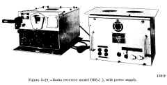
Radio Receiver RBS-( )
Although being replaced by newer and more efficient equipment, the model RBS-( ) radio receiver (fig. 3-27) still is installed aboard many
ships. It has a frequency range of 2 to 20 megacycles, which it covers in four tuning bands. A single tuning control provides variable
tuning throughout the frequency range. The model RBS-( ) radio receiver is capable of receiving CW, MCW, and voice signals.
When used in conjunction with a frequency shift converter, it also can be used for receiving RATT and FAX transmissions. The receiver does
not perform well in the reception of FSK signals, however. The reason is that an unstable oscillator has a tendency to drift off frequency
each time the ship rolls. |
 |
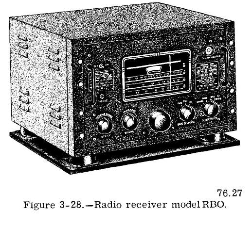
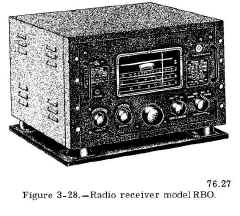
Radio Receiver RBO
The model RBO receiver (fig. 3-28) has been the standard shipboard entertainment receiver for many years. It is installed in ships of
all types. The RBO is a superheterodyne receiver. It provides high-quality reception of voice and music. Frequency bands of this
receiver are (1) the standard broadcast band, 530 to 1600 kc; (2) a shortwave band from 5.55 to 9.55 mc; and (3) another shortwave band
from 9.20 to 15.60 mc. |
 |
VHF RECEIVERS
In most instances, radio receivers covering the VHF (and UHF) range are operated as crystal-controlled equipments. They are tuned easily
and quickly. Once tuned, they operate efficiently for long periods of time without further attention.
As mentioned earlier in this chapter, the VHF range seldom is used for shipboard communications. Consequently, most ships carry only one or
two VHF receivers.
Two models of VHF receivers currently used aboard ship are the AN/URR-21( ) and the AN/URR-27( ). Of these two, the AN/URR-27( ) is
installed in greater quantity. For this reason, it is described first.
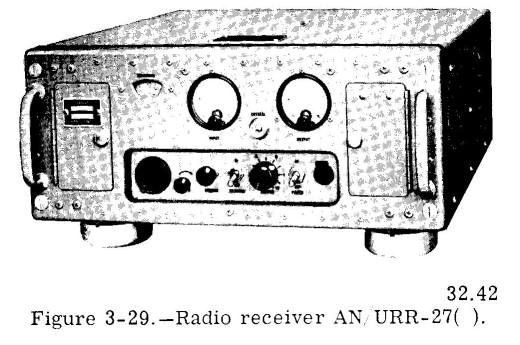
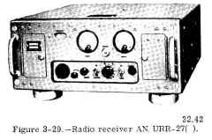
Radio Receiver AN/URR-27( )
Radio receiving set AN/URR-27 (fig. 3-29) for reception of amplitude-modulated and MCW transmission in the 105- to frequency range. You
will note that this range of frequencies slightly exceeds that VHF transmitters, which cover a band 115 to 156 mc. This extra
coverage, and below the transmitter frequency has no practical worth. It is, in effect,
wasted.
The AN/URR-27( ) is a superheterodyne receiver designed chiefly for operation as a
pre-tuned, single-channel, crystal-controlled receiver. Continuously variable manual tuning is - available. A single tuning control is used tuning to any frequency for either
crystal-controlled or manual tuning operation. |
 |
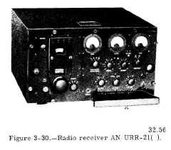
Radio Receiver AN/URR-21( )
The AN/ URR-21( ) receiver (fig. 3-30) is used for receiving amplitude-modulated radio' telephone signals, in a portion of the VHF
band, from 115 to 156 mc. It is a crystal-controlled superheterodyne receiver. Although the receiver dial is calibrated continuously, only
four channels can be tuned within the frequency range at any one time because the frequency
of the oscillator is controlled by four individually selectable crystals. The four crystals
are plugged into a crystal holder on the receiver chassis inside the cabinet. Special features include a front panel dial detent mechanism
for rapid selection of channels, and continuous tuning of all r-f circuits by means of a single tuning control.
This receiver is an improved version of the old model RCK, still installed aboard many ships. |
 |
UHF RECEIVERS
Because of the extensive use of the UHF band for tactical communications, the number of UHF receivers installed in the fleet far exceeds
other types of receivers. The majority of UHF receivers are models AN/URR-13( ) and AN/ URR-35( ). Like the VHF receivers, these UHF
receivers are crystal-controlled for stable operation over long periods of time.
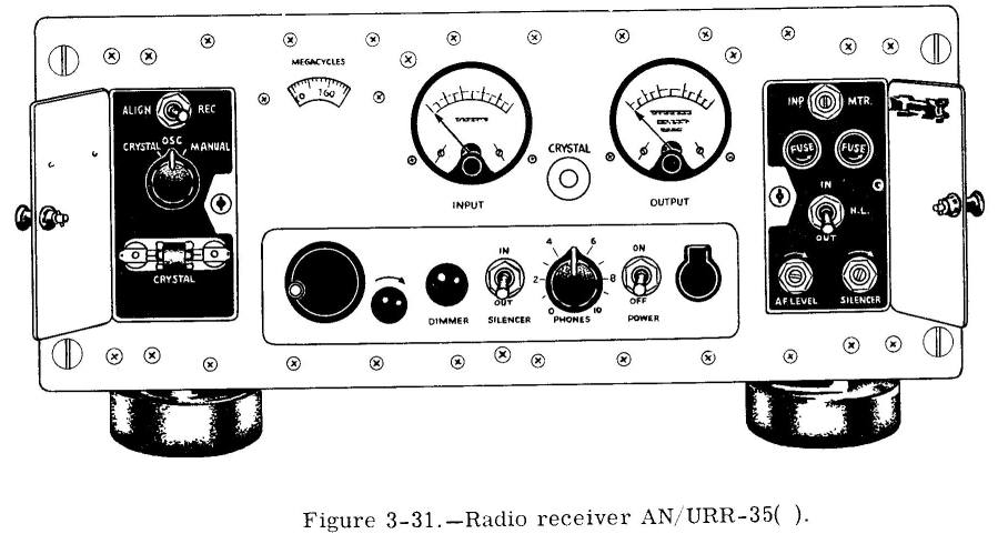
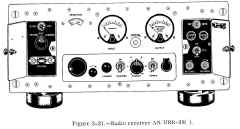
Radio Receivers AN/URR-13( ) and AN/URR-35( )
Radio receivers AN/URR-13( ) and AN,/URR-35( ) are used for radiotelephone and MCW reception in the range of 225 to 400 mc. Although the
frequency range includes the upper portion of the VHF band, both receivers commonly are called UHF equipments. They are used as companion
receivers with the model TED transmitter. They were designed mainly as single-channel, crystal-controlled receivers. Continuously variable
manual tuning may also be used. These receivers are easy to tune. They feature single tuning controls for tuning to any frequency within
their range, for either crystal-controlled or manual tuning. The AN/URR-13( ) is a superheterodyne receiver whereas the AN/URR-35( ) is a double superheterodyne. Both receivers are similar in size,
appearance, and operating controls. Only the AN/URR-35( ) is illustrated here. (See fig. 3-31.) |
 |
SHIPBOARD ANTENNAS
Antennas used for radio communications are so varied in design that it is impracticable to describe every antenna you may encounter aboard
ship. This section, consequently, deals mainly with the use and physical appearance of some of the more common shipboard communication
antennas. Any technical discussion of antenna theory is avoided, when possible. To understand why a particular antenna is suited for use at
one frequency (or range of frequencies), yet is unsuited for others, you must have a knowledge of the relationship between an antenna's
length and the frequency at which it is radiating.
The strength of the radio wave radiated by an antenna depends on the length of the antenna and the amount of current flowing in it. Be
cause the antenna is a circuit element having inductance, capacitance, and resistance, the largest current is obtained when the inductive
and capacitive reactances (opposition to the flow of alternating current) are tuned out: that is, when the antenna circuit is made
resonant at the frequency being transmitted.
The shortest length of wire that will be resonant at any particular frequency is one just long enough to permit an electric charge to
travel from one end of the wire to the other end and back again in the time of 1 cycle. The distance traveled by the charge is 1
wavelength. Because the charge must travel the length of the wire twice, the length of wire needed to have the charge travel l wavelength
in 1 cycle is half a wavelength. Thus, the half-wave antenna, sometimes called a dipole, doublet, or Hertz is the shortest resonant length
and is used as the basis for most antenna theory.
An antenna can be made resonant by two methods: (1) adjusting the frequency to suit a given antenna length; or, as usually is more
practicable, (2) adjusting the length of the antenna wire to accommodate a given frequency. Every time the transmitter is changed to a new
frequency, it is, of course, impracticable to lengthen or shorten an antenna physically. The antenna length may be changed electrically,
however, by a process known as tuning, or loading, the antenna.
T he dipole - a center-fed, half-wave antenna -is the basis for many complex antennas. When used for transmitting high frequencies, it usually
is constructed of wire. At very high and ultrahigh frequencies, the shorter wavelength permits construction with metal rods or tubing.
Because the dipole is an ungrounded antenna, it must be installed far above the ground or other absorbing structures.
At low and medium frequencies (below 4 mc), half-wave antennas are rather long for use aboard ship. Another basic type of antenna, however,
affords a solution to the problem of undue length. It is the quarter-wave (Marconi) antenna
The earth is a fairly good conductor for medium and low frequencies, and acts as a large mirror for the radiated energy. The
result is that the ground reflects a large amount of energy that is radiated downward from an antenna mounted over it. It is as though a
mirror image of the antenna is produced, the image being located the same distance below the surface of the ground as the actual antenna
is located above it. Even in high-frequency range (and higher), many ground reflections occur,
especially if the antenna is erected over highly conducting earth or salt water.
Utilizing this characteristic of the ground, an antenna only a quarter-wavelength long can made into the equivalent of a half-wave antenna
If such an antenna is erected vertically ad its lower end is connected electrically to the ground, the quarter-wave antenna behaves like a
half-wave antenna. Here, the ground takes the place of the missing quarter-wavelength, and the reflections supply that part of the radiated
energy that normally would be supplied by the lower half of an ungrounded half-wave antenna.
Another method of operating a vertical quarter-wave antenna is to use a ground plane with the antenna. The ground plane usually is made of
wires or rods extending radially from the base of the antenna. Actually, the ground plane substitutes for the ground connection, thereby
establishing the ground level at the base of the antenna. Thus, the antenna can be installed on masts or towers high above ground
Ground plane antennas of this sort are used mostly for VHF and UHF communications.
Although discussions of antennas ordinarily concern those used for transmitting, an efficient transmitting antenna for any particular frequency is also an efficient receiving antenna for that same frequency. It must be remembered,
however, that there may be other limitations affecting the use of an antenna for both transmitting and receiving.
Problems not usually present in land installations arise when antennas are installed
on board ship. Most of the masts, stacks, and other structures above decks are connected electrically (grounded) to the ship's hull and,
through the hull, to the water. To obtain adequate coverage from the antenna, it must be installed so that minimum distortion of the
radiation pattern results from grounded structures.
The antennas described in the next six topics are only a sampling of the antennas used in the Navy. They are typical of the antennas
you can expect to find installed aboard most Navy ships.
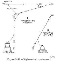
WIRE ANTENNAS
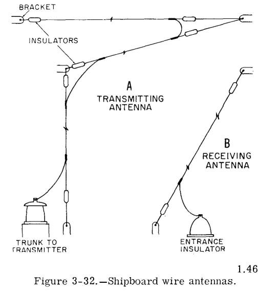
Wire antennas (fig. 3-32) are installed on board ship for medium- and high-frequency coverage. Normally, they are not cut for a given
frequency. Instead, a wire rope is strung either vertically or horizontally from a yardarm (or the mast itself) to outriggers, another
mast, or to the superstructure. If used for transmitting, the wire antenna is tuned electrically to the desired frequency.
Receiving wire antennas usually are installed forward on the ship, rising nearly vertically from the pilothouse top to brackets on the mast
or yardarm. They are located as far as possible from the transmitting antennas so that a minimum of energy is picked up from the local
transmitters. The transmission line (lead-in) for each receiving antenna terminates in antenna transfer panels in the radio spaces.
Transmission lines of the transmitting antenna may be of coaxial cable or copper tubing. They are supported on standoff insulators and in
some instances, are enclosed in rectangular metal ducts called antenna trunks. Each transmission line connects with an individual
transmitter or with an antenna multicoupler (discussed later).
Metal rings, antenna knife switches, antenna hardware, and accessories associated with transmitting antennas usually are painted red.
Hardware and accessories used with receiving antennas are painted blue. This color scheme is a safety precaution, and indicates, at a
glance, whether an antenna is used for radiating or receiving. |
 |
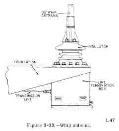
WHIP ANTENNAS
Whip-type antennas have replaced many wire antennas in the frequency range 1.8 to 30 mc. Because they are essentially self-supporting, whip
antennas may be installed in many locations aboard ship. They may be deck-mounted, or they may be mounted on brackets on the stacks or
superstructure (fig. 3-33). Whip antennas commonly used aboard ship are 25, 28, or 35 feet in length, and are made up of several sections.
On aircraft carriers, whip antennas located along the edges of the flight deck can be tilted. The tilting whip is pivoted on a trunnion,
and is equipped with a handle for tilting and erecting the antenna. A counterweight at the base of the antenna is heavy enough to nearly
balance the antenna in any position. The antenna may be locked in either a vertical or horizontal position. |
 |
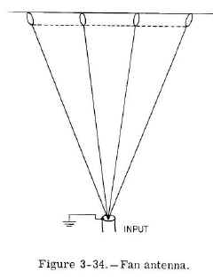
FAN ANTENNA
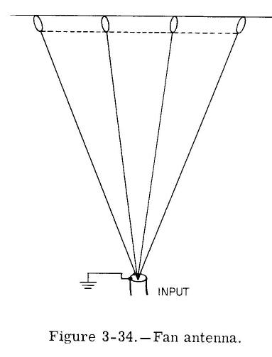
The fan antenna (fig. 3-34) is designed principally for use in the low-frequency range. It also performs satisfactorily at high frequencies. This antenna is capable of radiating over a wide range of frequencies, for which reason it is known as a broadband antenna.
The antenna usually consists of four radiating elements (wires) that are cut for one-quarter wavelength at the lowest frequency to be transmitted. Whether one or all of these elements are fed energy by the transmitter, the overall effect of the paralleled elements is to
increase the radiating surface. Effectively, the fan antenna is a single radiator whose diameter is substantially large in comparison to
its length. |
 |
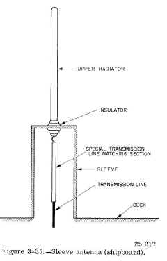
SLEEVE ANTENNA
The sleeve antenna (fig. 3-35), originally developed to fill the need for a versatile, long-distance antenna ashore, now is installed
aboard many ships. Essentially, the sleeve antenna is a grounded, quarter-wave antenna that operates over a wide range of frequencies in
the high-frequency band. Although similar in appearance to the whip antenna, it is identified easily by the large diameter sleeve at its
base. The sleeve usually is welded to the deck or superstructure of the ship. |
 |
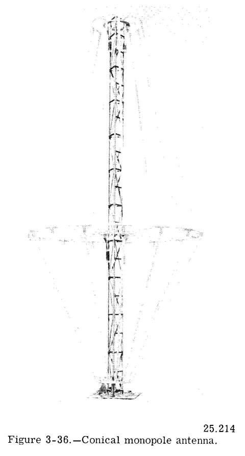
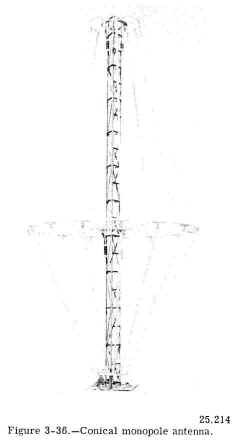
CONICAL MONOPOLE ANTENNA
Another broadband antenna used extensively is the conical monopole shown in figure 3-36. Like the sleeve antenna, it is used both ashore
and aboard ship. When operating at frequencies near the lower limit of the high-frequency band, the conical radiates in much the same manner as a regular
vertical antenna (omnidirectional on the horizontal plane). At the higher frequencies
the lower cone section radiates, and the effect of the top section is to push the signal out at a low angle. The low angle of radiation
causes the skywave to return to the earth at great distances from the antenna. Hence, the conical monopole antenna is well suited for
long distance communication in the high-frequency range. |
 |
VHF-UHF ANTENNAS
At VHF and UHF frequencies, the shorter wavelength makes the physical size of the antenna relatively small. Aboard ship these antennas are
installed as high and as much in the clear as possible.
For best results in the VHF and UHF ranges, both transmitting and receiving antennas must be mounted on the same plane (vertically or
horizontally). Vertically mounted antennas are used for all ship-to-ship, ship-to-shore, and air-ground VHF-UHF communications. Usually,
either a vertical half-wave dipole or a vertical quarter-wave antenna with ground plane is used.
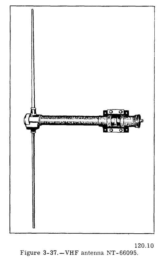
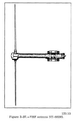
VHF Antenna 66095
The VHF antenna commonly installed aboard ships is Navy type 66095, shown in figure 3-37. The horizontal portion of the antenna does not
radiate, but acts as a mounting arm for the antenna and as an enclosure for the antenna feedline. The antenna is installed with the
radiating portion in the vertical position. Although designed originally for use with VHF transceiver AN/ARC-1, the antenna works
equally well with any transmitter and receiver operating in the frequency range 100 to 156 mc. |
 |
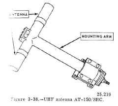
UHF Antenna AT-150/SRC
An antenna frequently used with UHF
installations is the AT-150/SRC (fig. 3-38). This antenna is of the half-wave (dipole) type, and it covers the frequency range 225 to 400
mc. Like the VHF antenna just described, the horizontal (longer) section does not radiate, but serves as a mounting arm for the antenna.
The antenna is mounted so that the radiator is vertical. |
 |
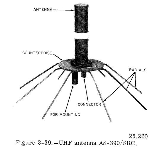
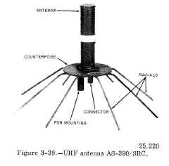
UHF Antenna AS-390/SRC
The AS-390/SRC (fig. 3-39) is another UHF antenna that operates at frequencies between 225 and 400 mc. It is a quarter-wave antenna with a
ground plane. The ground plane consists of a round plate (called a counterpoise) and eight equally spaced drooping radials (rods). The
antenna is mounted vertically. |
 |
UHF Antenna AS-1018/URC
The AS-1018/URC (not shown) is an additional 225- to 400-mc antenna often installed aboard ships. This antenna is the UHF version of the
broadband sleeve antenna described previously. |
no photo |
AUXILIARY EQUIPMENT
The term "auxiliary" often is misleading, particularly in the field of electronics. In most instances, material categorized as auxiliary
equipment is essential to the efficient operation of an overall system. But, because it is subordinate to the primary equipments, such as
transmitters, receivers, and antennas, it is classified as an auxiliary. Some of the more prominent auxiliary equipments used in communication systems are discussed in the ensuing topics of this chapter.
ANTENNA MULTICOUPLERS
Because of the large number of transmitters and receivers on board ships, it is infeasible to use a separate antenna for each equipment.
One satisfactory approach to the problem of antennas is provided by multicouplers. Antenna multicouplers are devices that permit the
simultaneous operation of several transmitters and/or receivers into (or from) the same antenna. The term "multicoupler" is descriptive of
two or more couplers stacked or grouped together to form a single equipment, which then is connected to a broadband antenna. A separate
coupler is required for each transmitter or receiver. Normally, the same antenna cannot be used for both transmitting and receiving
simultaneously.
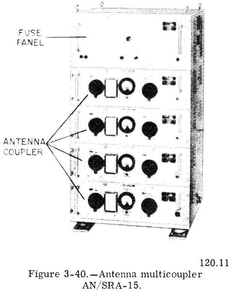
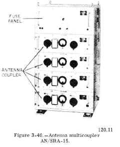
Multicouplers AN/SRA-13, -14, -15, -16
Four antenna coupler groups that operate the MF-HF range are the AN/SRA-13, -14,
-15, and -16. They provide complete coverage of
frequencies between 2 and 26 mc. The frequency coverage afforded by each multicoupler
as follows: AN/SRA-13, 2 to 6 mc; AN/ SRA-14, 4 to 12 mc; AN/5RA-15, 6 to 18 mc; and AN/SRA-16, 9 to 26 mc.
Typical of this group is the AN/SRA-15, which is illustrated in figure 3-40. The four couplers comprising the multicoupler provide for the
simultaneous operation of four transmitters (each with 500-watt power output) into a single broadband antenna. As long as there is adequate
separation between the operating frequencies, the four transmitters connected to the multicoupler may be operated anywhere in the frequency
range from 6 to 18 mc. Separation of 10 percent of the highest operating frequency is considered sufficient. |
 |
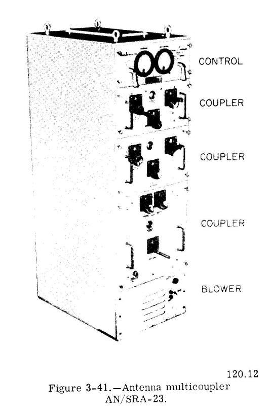
Multicoupler AN/ SRA-23
Antenna multicoupler AN /SRA-23 (fig. 3-41) consists of three couplers and associated control and blower units. The couplers cover the frequency range 2 to 27 mc in three frequency bands. Each coupler operates in a different band. These bands are 2 to 6 mc, 5 to 15
mc, and 9 to 27 mc. The coupler group was developed for use with 500-watt transmitters, but, with minor adjustments. it is capable of handling
transmitters with 1000-watt outputs.
One coupler group accommodates only one transmitter. Provisions are made, however, for connecting up to eight of these groups
together to form a multicoupler system. This arrangement permits the simultaneous operation of eight transmitters into a single broadband
antenna. |
 |
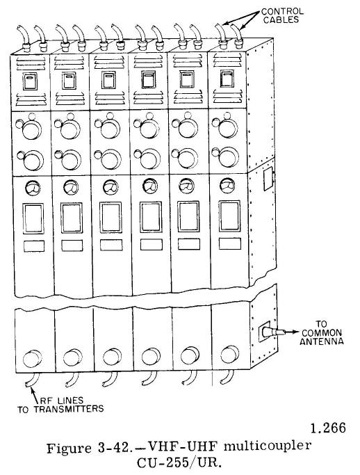
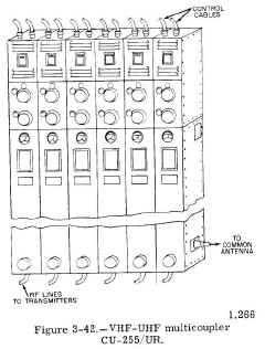
Antenna Couplers CU-255/UR and CU-332A/UR
One type of VHF-UHF antenna coupler is the CU-255/UR,
seen in figure 3-42. When six couplers are used (as shown), a multicoupler
system is provided for operating six transmitters (or transmitter-receiver
combinations) into a single antenna. One coupler is required for each
transmitter or transmitter-receiver combination. The frequency range of
this particular multicoupler is 230 to 390 mc. The CU-255/UR couplers can
be tuned manually to any frequency in this range. When used with automatic
tuning transmitters, such as AN/ GRC-27, they may be tuned automatically
to any one of 10 preset channels in this band. Automatic tuning is
accomplished by dialing the desired channel locally on the transmitter or
on a remote channel-selector unit.
Type CU-332A/UR antenna coupler is identical to the
CU-255/UR, except for the drive mechanism. The CU-332A/UR provides for
manual tuning only, whereas the other has both automatic and manual
tuning. The CU-332A/UR is used with manually tuned UHF equipment, such as
the model TED transmitter, or any other manually tuned equipment operating
in the 230- to 390-mc frequency range. Like most VHF-UHF couplers, the
performance characteristics of these two types of couplers require that
operating frequencies on the common antenna be separated by approximately
15 mc. |
 |
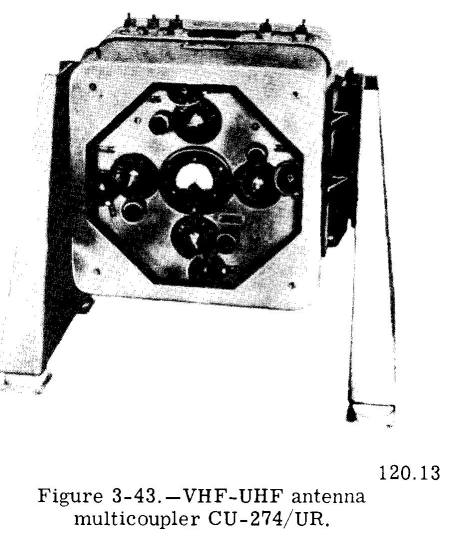
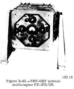
Multicoupler CU-274/UR
Although not as efficient as the multicouplers just described, the CU-274/UR (fig. 3-43) is installed aboard small ships where space is a
prime consideration. It provides for simultaneous operation of four UHF radio channels (transmitting or receiving) into a single
antenna.
This multicoupler can be tuned either automatically or manually to any frequency in the range 225 to 400 mc. For automatic tuning each
channel first must be pretuned to 10 corresponding frequency channels in the frequency range of the attached transmitter or receiver.
Thereafter, selected channels are returned automatically by means of an autotune mechanism. |
 |
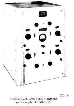
Multicouplers CU-691/U and CU-692/U
Both the CU-691/U and the CU-692/U are VHF-UHF multicouplers operating at frequencies between 225 and 400 mc. Except for their physical
dimensions and the number of channels, the two sets are identical. The CU-691/U provides for the operation of four transmitters or
receivers, whereas the CU-692/U accommodates only two. Both multicouplers are tuned manually. The CU-691/U is shown in figure 3-44. |
 |
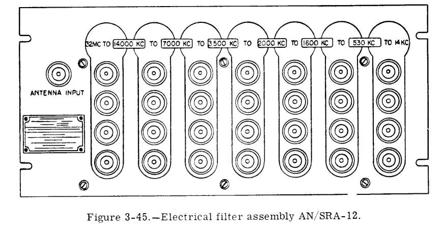
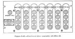
Receiving Multicouplers AN/SRA-9 and AN/SRA-12
Electrical filter assemblies (multicouplers) AN/SRA-9 and AN/SRA-12 are identical in appearance and function. They are receiving antenna
distribution systems that make possible the multiple operation of a maximum of 28 radio receivers from a single antenna. Ordinarily it is
preferable, however, to limit the total number of receivers to seven.
The AN/SRA-12 (fig. 3-45) filter assembly provides seven radio frequency channels in the frequency range from 14 kc to 32 mc. Any or all of
these channels may be used independently of any of the other channels, or they may operate simultaneously. Connections to the receivers are
made by means of coaxial patch cords, which are short lengths of cable with plugs attached to each end.
A set of nine plug-in type filter subassemblies is furnished with the equipment, but only seven of them may be installed at one time. The
seven filters installed are selected to cover the most-used frequency bands. |
 |
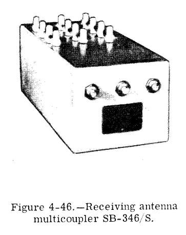
Receiving Multicoupler SB-346/ S
Another receiving antenna multicoupler is the SB-346/S, on view in figure 3-46. This small panel enables operation of 12 receivers from
three antennas. Each antenna is utilized by four receivers. Although not as satisfactory an arrangement as the AN/SRA-12, this unit can be
installed aboard small ships where available space is limited. |
 |
TRANSMITTER AND RECEIVER TRANSFER PANELS
Transmitter and receiver transfer panels are an integral part of every shipboard radio system. They make it possible to connect
transmitters and receivers to remote control points located throughout the ship. These transfer panels formerly were of the cumbersome
patch cord type, but those currently installed aboard ships are of the switchboard type described here.
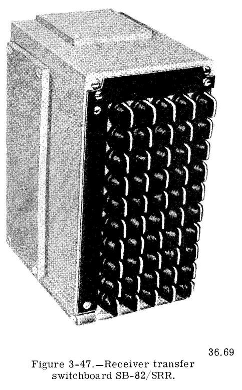
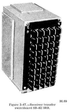
Receiver Transfer Switchboard SB-82/SRR
Receiver transfer switchboard, type SB-82/SRR, is shown in figure 3-47. The
receiver switchboard has five vertical rows of ten single-throw (ON-OFF) switches that are continuously rotatable in either direction. One side of
each switch within a vertical row is wired in parallel with the same sides of the other nine switches within the row. Similarly, the other
side of each switch is wired in parallel horizontally with the corresponding sides of each of the other four switches in a horizontal row.
This method of connecting the switches permits a high degree of flexibility.
In general, there are more remote stations than radio receivers, hence the audio outputs five receivers are fed to the five vertical rows
and ten remote stations are connected the ten horizontal rows. With this arrangement, a selected receiver output is connected to any or all
of the remote stations by closing the proper switch(es). When one switchboard is inadequate for accommodating all of : receivers and remote stations installed in
ship, several of these switchboards are mounted together and interconnected so that
they form a bank of switchboards.
The knob of each switch is marked with heavy white line to provide visual indication of whether the switch is in the ON or OFF position
Switchboards always are installed with the line positioned vertically when the switch is open (off). To further standardize all
installations, receivers usually are connected to the vertical rows of switches, and remote stations are connected to the horizontal rows. Identification of the receivers and remote
stations is engraved on the laminated bakelite label strips fastened along the top and left edges of the panel front. |
 |
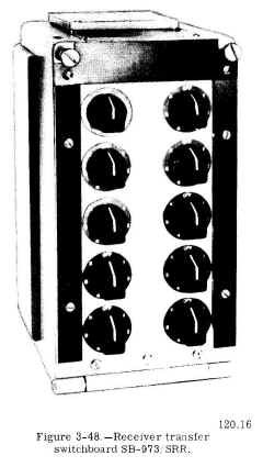
Receiver Transfer Switchboard SB-973/SRR
A recent model receiver transfer switchboard is the
SB-973/SRR, illustrated in figure 3-48. This switchboard contains 10 seven
position rotary selector switches. Each switch or operating knob relates
to a remote control station Switch positions one through five relate to
receivers.
Position X on each switch serves to transfer the remote
control stations connected to the original switchboard to the
corresponding switches in additional switchboards. In this manner, any
number of receivers can be connected to the ten remote control stations.
An additional switchboard is needed for each five additional receivers.
Switchboards providing facilities for additional remote
control stations are mounted in vertical sequence, whereas those
containing additional receivers are mounted in horizontal sequence. |
 |
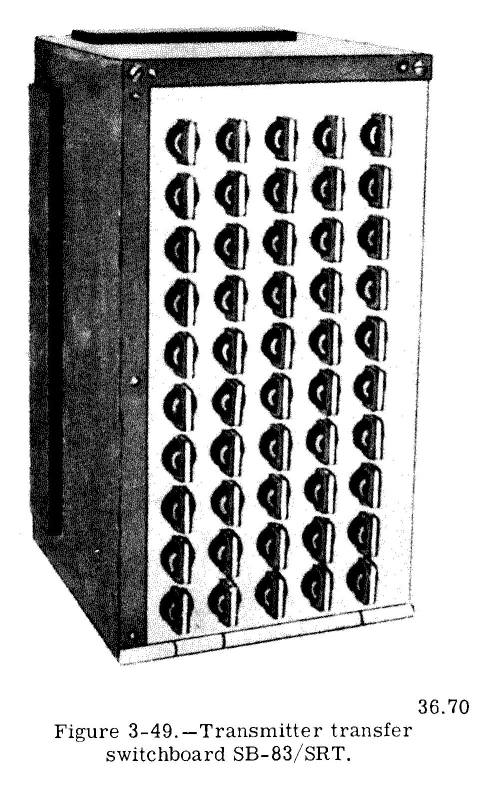
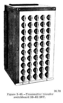
Transmitter Transfer Switchboard SB-83/SRT
Transmitter transfer switchboard, type SB83/SRT, is shown in figure 3-49.
The switchboard has five vertical rows of ten switches. Radio transmitters are wired to the five vertical rows; remote stations are connected
to the ten horizontal rows. Switches are off when the white lines on the knobs are vertical.
Although the switches are of the continuously rotatable type, most switchboards are equipped with a spring-loaded, mechanical inter lock
that allows the switches to be closed by turning the knobs in a clockwise direction. The switches then are opened by turning the knobs
counterclockwise. The interlock also prevents additional switches in each horizontal row from being closed when any one of the five
switches in that row is closed already. This arrangement prevents serious damage that is certain to result from two or more transmitters
feeding a single remote-control station at the same time.
By wiring several of these boards together, facilities are available for transferring any transmitter to any or all remote control
stations. |
 |
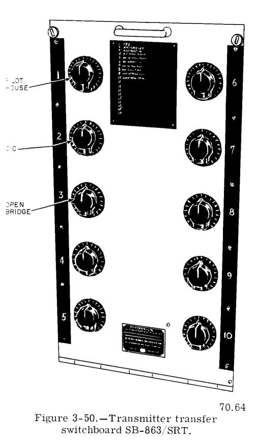
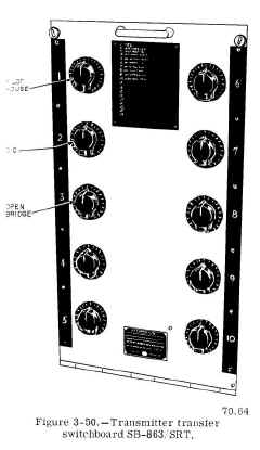
Transmitter Transfer Switchboard SB-863/SRT and SB-988/SRT
The models SB-863/SRT and SB-988/SRT transmitter transfer switchboards are replacing the SB-83/SRT in shipboard installations. Except for
their transmitter-handling capacity, these two newer switchboards are identical. The SB-863/SRT (fig. 3-50) handles up to 19 transmitters,
whereas the SB-988/SRT (not illustrated) handles only 6.
Both of these switchboards have 10 rotary selector switches in two vertical columns. Each rotary switch corresponds to a remote-control
station, and each switch position either corresponds to a controlled transmitter or serves to transfer the remote station to an adjacent
switchboard. The remote station assigned each rotary switch and the transmitter assigned each switch position are identified on the
bakelite plates attached to the front of each switchboard. |
 |
| |
|
| |
|
REMOTE-CONTROL UNITS
To operate radio transmitters from remote locations requires the use of remote-control units. Most of these units are used as radio phone
units. (RPUs). They provide for energizing and deenergizing transmitters, for connecting microphones, handsets, chestsets, telegraph keys, and headphones, and for controlling the audio output level (volume) of radio
receivers. Some units also enable remote selection of radio channels when they are utilized to control multichannel transmitters and
receivers (such as the model AN, GRC-27).
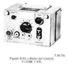
Radio Set Control C-1138( )/UR
Radio set control C-1138( )/UR (fig. 3-51) is a remote-control unit designed for installation in protected locations, as in the CIC or
pilothouse. This unit contains a start-stop switch for turning a transmitter on or off, jacks for connecting a handset or chestset,
microphone, headphones, or telegraph key, a volume control for the headphone or loudspeaker, and indicator lamps for transmitter-on (power)
and carrier-on indications. Although provisions are made for CW operation, the unit seldom is used for this purpose. In most instances it
is utilized for radiotelephone communications.
By means of transmitter and receiver transfer switchboards, as many as four of these remote-control units may be connected to the same
transmitter or receiver. This arrangement is utilized when it is necessary that a radio channel be controlled from more than one remote
location.
The model C-1138( ) /UR is an improved version of the older and slightly larger remote-control unit NT-23500, still in service aboard
many ships. The two units are similar in appearance and function, hence the older set is not described nor illustrated here. |
 |
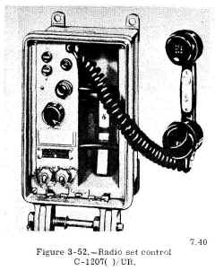
Radio Set Control C-1207( ) /UR
Radio set control C-1207( ) /UR, shown in figure 3-52, is designed for installation in areas that are exposed to the weather. Access to
its controls is obtained by opening the front cover, which is hinged to the unit. The controls, consisting of a handset, a transmitter
start-stop switch, and a receiver volume control, are mounted on the front panel of the unit. Also
mounted on the panel are two indicator lamps that provide visual indication of whether the transmitter power and carrier-on circuits are
energized or deenergized, and two jacks for connecting a chestset and a set of headphones.
When connected to a standard shipboard transmitter and receiver, the C-1207( ) /UR permits remote control of the following functions: (1)
energizing and deenergizing the transmitter, (2) voice modulating the transmitter input, and (3) controlling the audio output of the
receiver. As many as four of these units may be connected to the same transmitter and receiver. |
 |
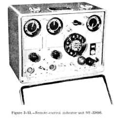
Remote-Control/ Indicator Unit NT-23496
Although designed for use with a now obsolete transmitter-receiver combination, the
remote-control/indicator unit NT-23496 still is used aboard many ships for controlling multichannel transmitters and receivers. The unit,
illustrated in figure 3-53, is capable of handling a transmitter and two receivers simultaneously. This arrangement permits guarding two
radio channels, with the transmitter available for use on either channel. By operating an equipment selector switch and a dial-type channel selector, the operator can select any of ten
preset radio channels on any multichannel transmitter or receiver controlled by the unit. A set of the usual remote controls is
provided for each equipment operated by the remote-control unit. |
 |
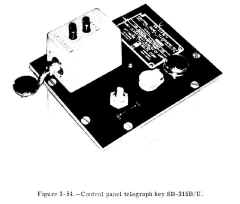
Control Panel Telegraph Key SB-315B/U
Control panel telegraph key SB-315B/U (fig. 3-54) contains the components and circuitry necessary to control the operation of a radio
transmitter from a remote position. Located on the plastic control panel are (1) a toggle switch for turning the transmitter on or off, (2)
an indicator light that glows red when the transmitter is on, (3) a telegraph key that provides a means for keying the transmitter, and (4)
a key jack that provides for an auxiliary telegraph key.
This combination control panel and telegraph key is used in conjunction with a CW transmitter for the purpose of transmitting messages in
international Morse code. |
 |
LOUDSPEAKERS AND AMPLIFIER UNITS
In certain instances, utilizing loudspeakers and their associated audio amplifier units to monitor radio communication channels is more
advantageous than using headphones. When a ship is involved in a rapidly changing tactical situation, for example, information received
over the tactical voice circuits is of vital concern to most bridge and CIC personnel. By placing these circuits on loudspeakers, all
incoming information is available instantly to everyone within hearing distance of the loudspeakers.
Four equipments currently installed aboard ships for use in monitoring voice (or CW) communication channels are the
audio amplifier unit
AM-215( )/U, loudspeakers NT-49546 and LS-195/U, and amplifier-speaker unit NT49545.
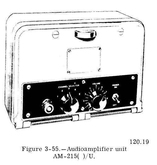
Audio amplifier Unit AM-215( )/U
The AM-215( )/U (fig. 3-55) is an audio amplifier unit that amplifies low-level audio signals for reproduction through loudspeakers. As many
as five radio receivers and five loudspeakers can be connected to this unit, but only
one signal is amplified and reproduced at any one time. The signal to be amplified and reproduced is selected by means of a channel
selector switch located on the front of the am plifier unit. Other controls on the unit's front panel are a volume control, a power
on-off switch, and a power-on indicating lamp. Usually these units are used in conjunction with the NT-49546 loudspeaker, described next. |
 |
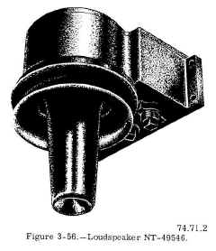
Loudspeaker NT-49546
Although it is a general-purpose communication loudspeaker, the NT-49546 (fig. 3-56) is used principally for reproducing voice transmissions. The unit can be connected directly to a radio receiver, or it can be operated through an
audio amplifier unit, such as the
AM/215( )/U. Best results are obtained with the audio amplifier unit. The loudspeaker, designed as a watertight and shockproof unit for installation in exposed areas, also is used extensively in such spaces as
the pilothouse and CIC. It usually is mounted on the bulkhead above or near its controlling amplifier unit. |
 |
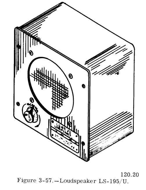
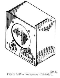
Loudspeaker LS-195/U
Another general-purpose communication loudspeaker is the LS-195/U, shown in figure 3-57. Like the NT-49546, this unit is used mainly for
monitoring voice channels. Unlike the NT-49546, however, the unit cannot withstand prolonged exposure to the weather; it is designed for
installation in protected areas only. In addition, it has a front panel volume control and is transportable, whereas the
NT-49546 has a preset, covered volume control and is mounted permanently. |
 |
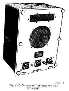
Amplifier-Speaker Unit NT-49545
The Navy type 49545 amplifier-speaker unit, seen in figure 3-58, is a combination
audio amplifier and loudspeaker assembly. Its reproduction qualities are considered good. Aboard most ships, it is installed in berthing and messing compartments as an entertainment
loudspeaker.
All operating controls of the unit are located on the front panel. They consist of a power on-off switch, a power-on indicating lamp, a
tone control, a volume control, and a channel selector switch that permits selection of up to five different entertainment (or
communication) channels. |
 |
FREQUENCY METERS
Frequency meters (standards) are instruments for tuning transmitters/receivers and determining the frequency of received signals.
In the past, few transmitters could be tuned without a frequency meter. With the current trend toward equipment that utilizes automatic
frequency selection and control, the frequency meter is used more as a test equipment than as a required equipment for the operational
tuning of transmitters. Although test equipment, as such, is not described in this text, frequency meters are included because they are
necessary for the proper tuning of some of the old-type transmitters still in service aboard numerous ships.
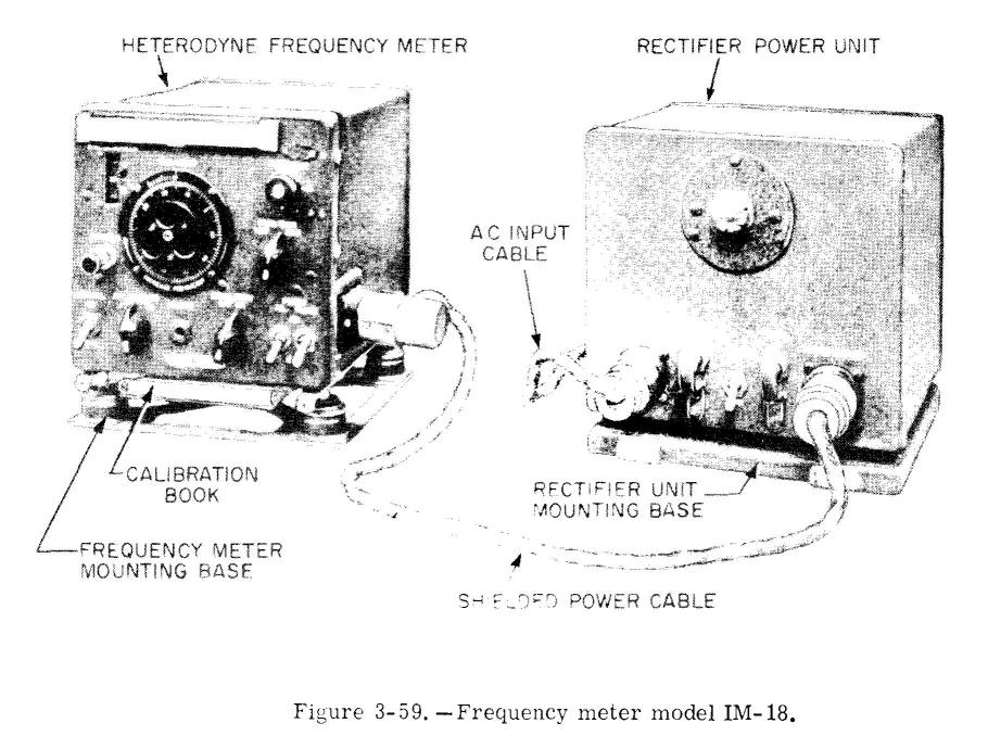
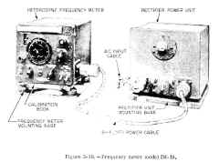
Frequency Meter IM-( )
Several models of the IM-( ) frequency meter have been
built. Except for the power supply and some minor mechanical differences,
these models are similar. The model IM-18 frequency meter, shown in figure
3-59, is representative of the IM series. It offers a simple, accurate
means of adjusting transmitters and receivers to and desired frequency in
the range from 125 kc to 20 mc. It serves both as a heterodyne frequency
meter for transmitter adjustment and as a signal source for receiver
calibration. It also is used for measuring the frequency of received
radio signals.
The IM-18 is accurate within ,02 percent in the 125- to
2000-kc band, and within .01 percent in the 2000-kc to 20-mc band. |
 |
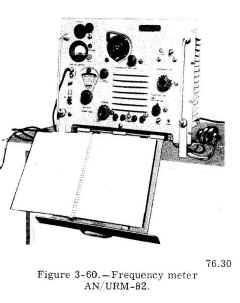
Frequency Meter AN/URM-82
One of the frequency meters now replacing older models is AN/URM-82, illustrated in figure 3-60. The AN/URM-82 is a precision instrument
for measuring frequencies in the range of 100 kc to 20 mc. It is used also to tune radio transmitters to an accuracy of .001 percent.
Features of the AN/URM-82 include a blinker light, in addition to earphones, to provide visual as well as aural
indications of correct frequency settings. A built-in cathode ray tube aids in adjusting the frequency meter to the desired frequency. |
 |
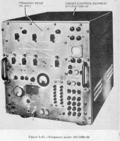
Frequency Meter AN/USM-29
Frequency meter AN/USM-29 (fig. 3-61) is designed for precise generation or measurement of frequencies in the range of 15 kc through 30 mc.
Output frequencies generated by the frequency meter are controlled by eight dials arranged on a decade basis. The value set up on the dials
is the frequency generated by the equipment. The generated signal is accurate to within .0001 percent of the value selected on the dials.
When measuring a signal of unknown frequency, the AN/USM-29 compares the unknown frequency against the accurate, known frequency it is
generating. It presents the results of the comparison both aurally and visually by means of headphones, an indicating meter, and a cathode
ray tube. |
 |
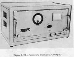
Frequency Standard AN/URQ-9
One of the latest frequency standards is the AN/URQ-9, pictured in figure 3-62. This highly stable frequency standard is designed for
continuous-duty use aboard ships and at shore facilities. It has three fixed output frequencies: 5 mc, 1 mc, and 100 kc.
Because it is intended as a frequency standard against which other frequency-generating
equipment can be compared, the AN/URQ-9 is energized and calibrated at special calibration laboratories. Once it is placed in operation and is calibrated properly, the frequency standard
must not be turned off. Any interruption in its operation will cause a change in its output frequencies. Hence, the equipment is transferred to the using activity while still operating.
A battery, which is built into the equipment, maintains operation during the time the frequency standard is in transit. It also supplies
power to the unit in the event of power failure aboard ship. When fully charged, the battery is capable of operating the equipment for
approximately 2 hours. |
 |
TRAINING DEVICES
For shipboard training purposes, the availability of the actual radio equipment makes it unnecessary to maintain a large number of special
training devices. Most radio equipment can be arranged to simulate actual operating conditions. Such an arrangement., moreover,
provides a more realistic training situation than can be attained by using special equipment.
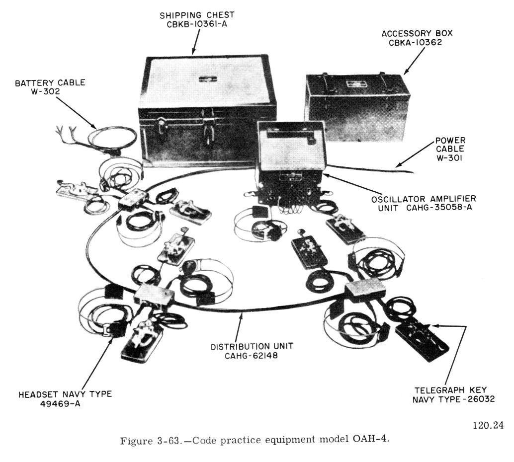
Code Practice Set OAH-4
One training device available for use in training radiotelegraph operators is the model OAH-4 code practice equipment. (See fig. 3-63.) The
equipment provides facilities for as many as seven operators at one time. and it can be used for both sending and receiving international
Morse code. The operators may be grouped into one, two, or three communication nets. Such grouping permits the exchange of
messages between operators under realistic operating conditions. |
 |
ADDITIONAL RADIO EQUIPMENT
The radio equipment described in the preceding text is mostly of the general-purpose communication type. Additional and more specialized
types of radio equipment are discussed in the following chapter, as well as in chapter 9.
US Navy Radio Pages