Also see
- Antenna Installation Info - from 1963 EIMB
- NAVSHIPS 0967-177-3020, SHIPBOARD ANTENNA SYSTEMS
- NAVSHIPS 900121(A) SHIPBOARD ANTENNA
DETAILS
- Chapter 2 Installation Methods (incl. change 1) - download pdf
- Chapter 3 Multicouplers - download pdf
- Chapter 6 Antenna Systems - download pdf
- Chapter 8 Installation Bibliography - download pdf
- Antenna Catalog Vol III, Ship Antennas (1960) - download 10 MB pdf
- Technical Report - Nearfield Calculations for Shipboard Antennas
- Topside Antenna Design Process
- Shipboard VHF/UHF Antenna Analysis
- 1945 Premax antenna catalog
- USS Canopus (AS-34) Antenna Plans
- "Shipboard Antennas" by Preston E. Law - link
- Need more info!!
ANTENNA MODELING
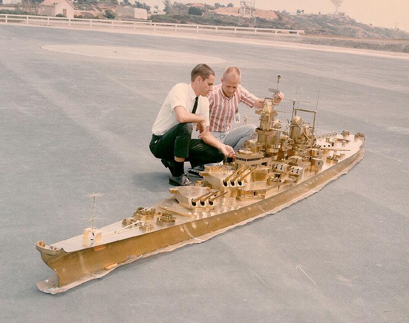
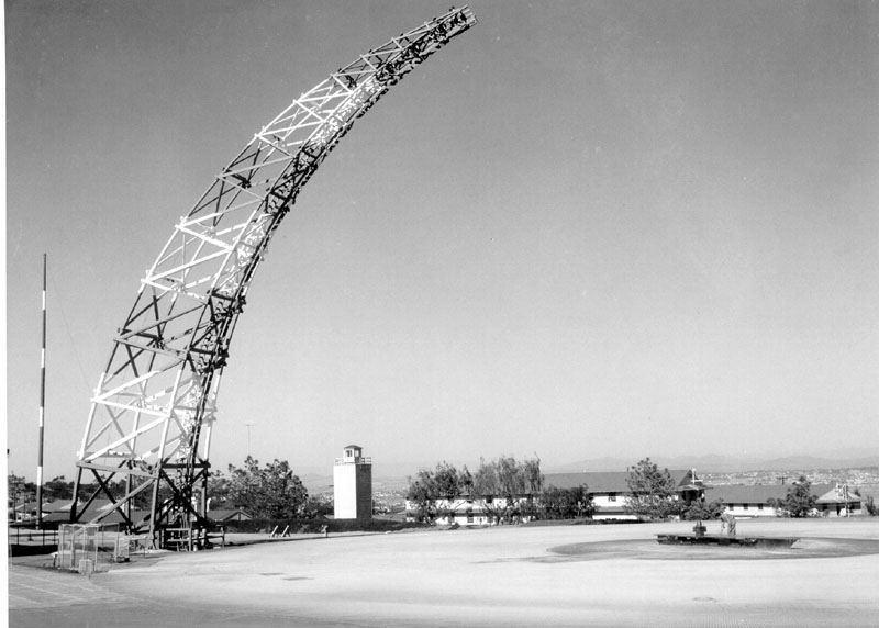
Shipboard antenna modeling uses brass models in a lead "sea". Receiver probes are inserted from a room underneath the model while test signals are transmitted from the gantry. The model is 1/48 scale and the frequencies used are 48 times higher than actual. Newer computer modeling is also used.
- Excellent magazine article - Popular Mechanics April 1959
- photo showing model and newer antenna gantry
- Close-up photos of USS Missouri brass model
- CG-10 model restoration
- Models in storage
- Model building article
- Technical Paper - "Performance Prediction Analysis for Shipboard Antenna Systems"
- busted SWRI link - From brass to computer shipboard antenna modeling
- Another technical paper
- SPAWAR - Range info
- busted SPAWAR link - Model building info
- Some info and photos


**See 1949 Press Release below


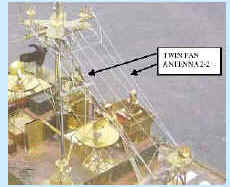

Antenna detail on CG-10 model
In planning communications systems for ships at sea, Navy scientists seek to design shipboard antennas capable of sending out substantially the same amount of energy on all directions.
This problem is attacked at the US Navy Electronics Laboratory, San Diego, California, by the use of miniature ships whose topside structures are precisely scaled counterparts of full-sized naval vessels. these models make it possible to conduct investigations of shipboard antenna directivity under controlled conditions on land. Scale factors of 1/12, 1/24, and 1/48 are used in the studies and are applied both to the construction of the miniature ships and to the radio wavelengths most commonly encountered in shipboard communications.
In practice, the scale model is mounted on a turntable and rotated over a mesh of hardware cloth while it antennas are supplied with energy at the correct radio frequency. The hardware cloth simulates the conductivity of the ocean at regular communication frequencies. The radiated energy is received and its intensity measures at special stations on the rim of the "ocean". These measurements give radiation characteristics of the small antenna, and by extension, the performance of a full size antenna aboard a full size ship at communication frequencies.
The model shown is one of the "Long Hull" destroyer class, and is constructed of brass. The use of such models for antenna directivity studies avoids the heavy expenditures of money which would be necessary to obtain the same data if full-scale, fully manned ships were used at sea for this purpose.
A strangely silent fleet of brass warships can be seen operating on a lead-coated "ocean" high and
dry atop the main NEL premises on Point Loma. The ships in this fleet never fire their guns, but their
antennas are always busy. Built to 1/48 scale, they are part of the Laboratory's unique ship model
antenna range.
Each ship is electronically complete down to the waterline. Each has operational antennas for transmitting and receiving radio signals
at varying frequencies. Because metallic ship environments distort and alter the radiations from antennas, and obstructions topside
provide added interference, antenna efficiency usually depends upon the placement, design, and
number of the antennas.
The Laboratory tests the efficiency of a particular antenna design by sending and receiving signals in all frequencies while the
ship model turns through the 360° of azimuth on a 22-foot turntable in the center of a 160-foot
lead and wire-coated field. The coating provides environmental conditions roughly approximating those of the
ocean.
An actual ship could make only a limited number of turns in a day, with consequent loss of operational
time, manpower tieup, and interruption of other training. Moreover, changeable weather conditions
would prohibit testing under controlled physical conditions, as is possible on a controlled range.
A further great advantage of the range is the design and test of communication systems as an aid
to ship preliminary design. Technically, the artificial ocean is a conducting ground plane, and the experiments measure on the
ship models vertically polarized components of horizontal-plane patterns in the 96 to 1440 megacycle
range, simulating the 2- to 30-megacycle band.
A two-axis free space mount, available for measurement of zenith coverage patterns in the
1000 to 3000-megacycle range, can accommodate scale models (usually 1/4 scale) of ship masts and superstructures. Use of a wire mesh
ground plane of about 40,000 square feet with five 90-foot wood poles permits realistic full-scale tests
of simulated ship antenna systems, and an additional 120-by-150 wire mesh ground plane has a rotating
antenna mount for development and test of specific antennas for ship and shore applications.
Ship communication mock-up facilities in the antenna range building make possible the study and
development of complete ship radio communication systems under conditions simulating those aboard
ship. Improvements now under way at the ship model range will permit absolute measurement of antenna
patterns and extension of measurement to evaluation angles above the horizon.
Nearby microwave facilities include a range for rapid and accurate determination and recording of the
free space radiation patterns, impedance, and gain characteristics of microwave antennas in the frequency range from 1000 to 10,000
megacycles.
NEL engineers must study as many as 3,000 to 5,000 radiation patterns for each new ship design. To
lighten their workload the antenna range specialists recently devised a Pattern Analyzer Computer
(analog to digital) equipment which is used to determine values required from the antenna patterns by an
IBM computing machine.
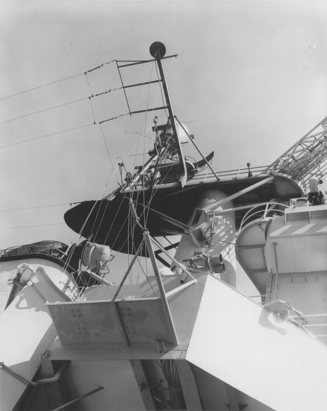
MYSTERY ANTENNA USS Ticonderoga CVA-14
- please send email if you have
additional info

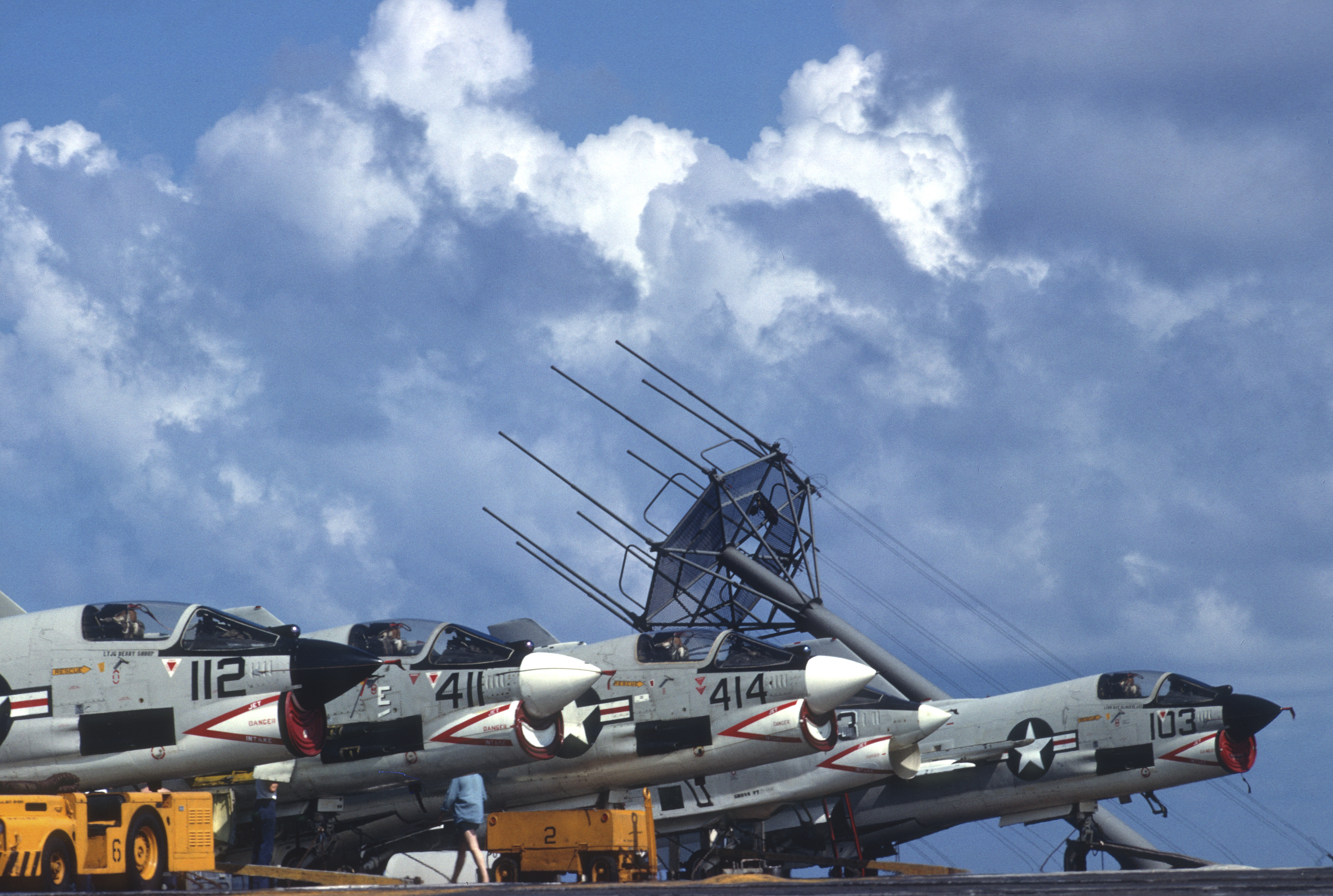

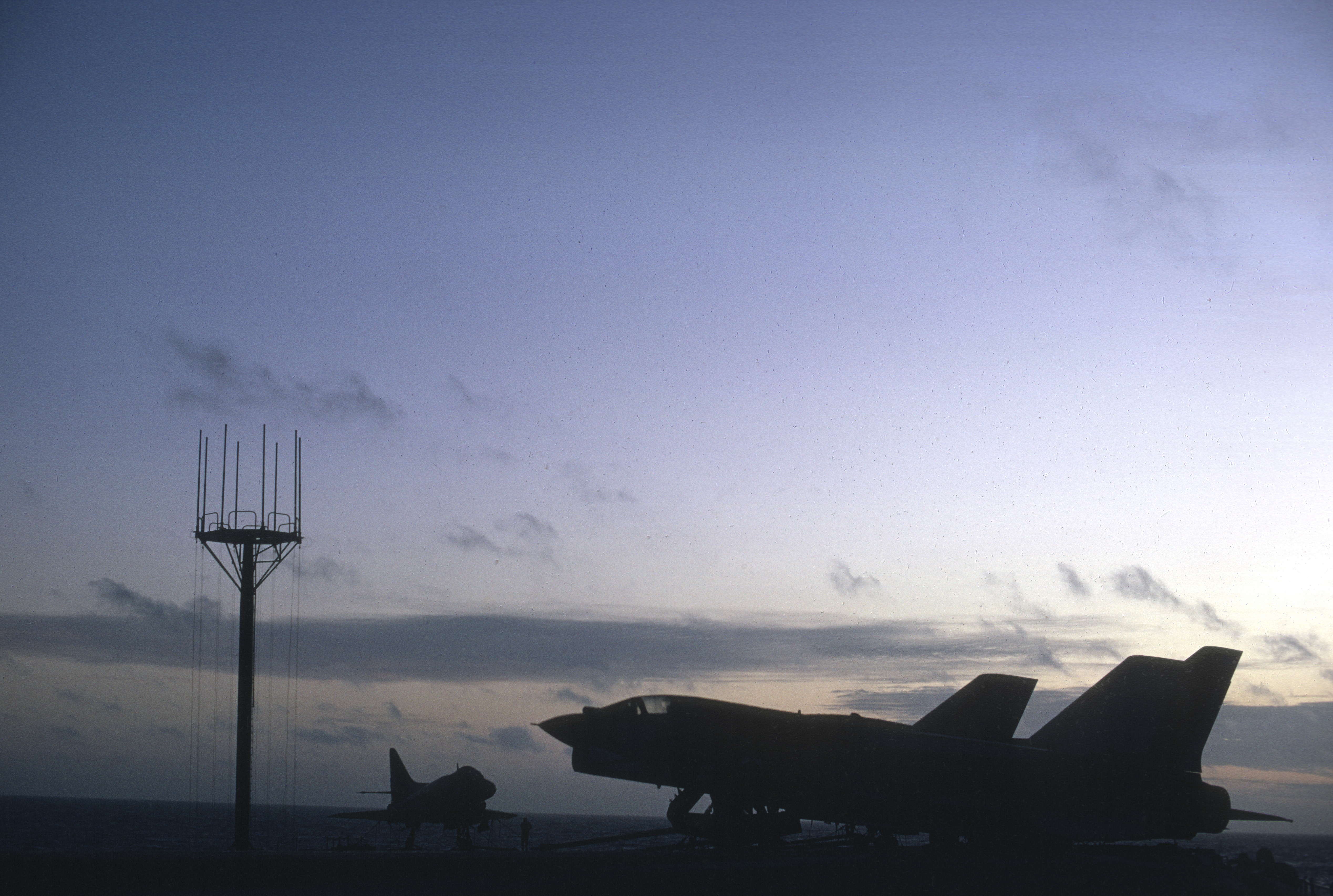
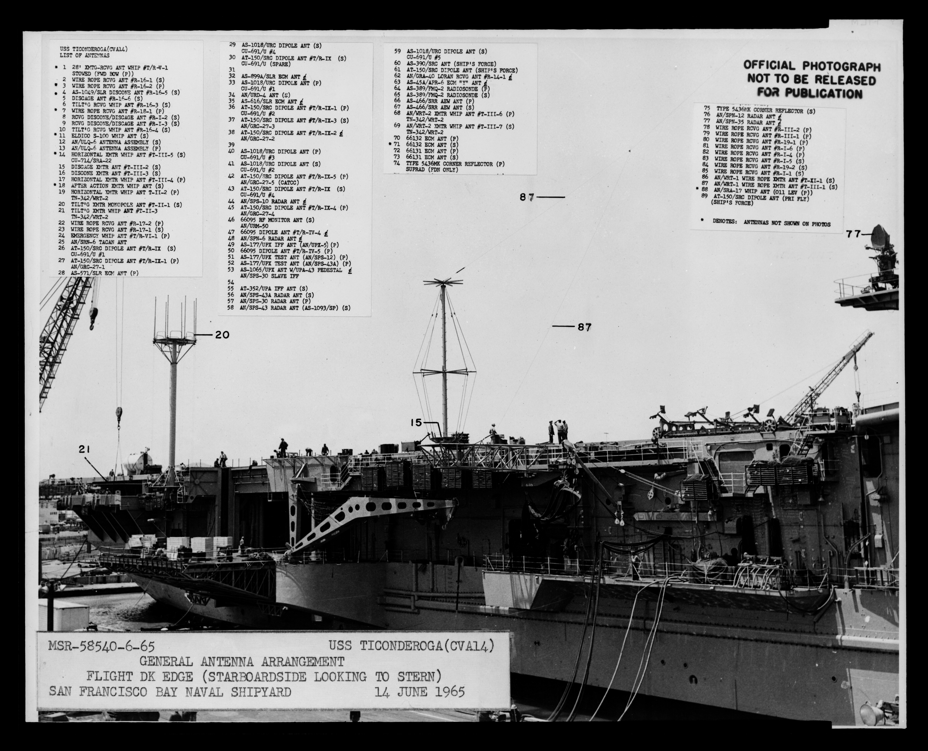
Info from a Ticonderoga ET - "The pickle fork was a multiple whip MHF antenna... It had, if I remember correctly, eight whips on a platform about 10 feet across and mounted on a single pole which could be tilted seaward when launching and recovering aircraft... The whips were all attached to a netting of copper cables which surrounded the base of the platform and electrically lengthened the antennas ..It was fed by ten tuners which were a combination of capacitance and inductance in series and parallel to the antenna, and would also electrically lengthen and shorten the antenna in an attempt to reach the point of resonance..... The radio men would attempt to tune it to a SWR of 1:1 for maximum power out...`the advantage was that if the frequencies had enough split between them, we could put ten transmitters up on a single antenna.."
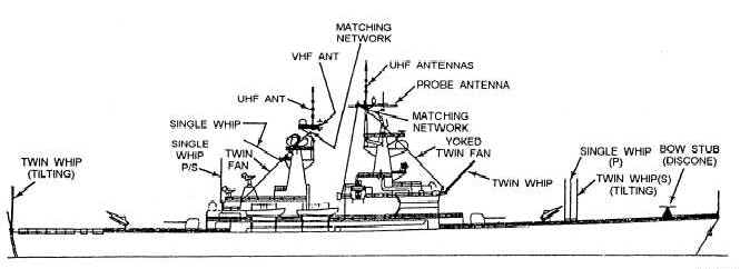
Typical Ship Antenna Arrangement
 (#1)
On the bow of the Jersey is the disc-cage antenna. Originally developed
for use with the Naval Tactical Data System {NTDS) during the 1960's, it
was used as transmit only during the 1980's. This is actually two
antennas, a Disc and a cage. The larger Cage portion consists of the wires
while the smaller Disc section is the set of spokes at the top of the
pole.
(#1)
On the bow of the Jersey is the disc-cage antenna. Originally developed
for use with the Naval Tactical Data System {NTDS) during the 1960's, it
was used as transmit only during the 1980's. This is actually two
antennas, a Disc and a cage. The larger Cage portion consists of the wires
while the smaller Disc section is the set of spokes at the top of the
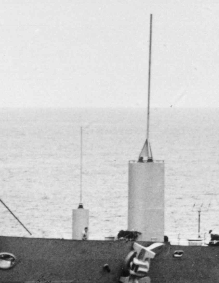
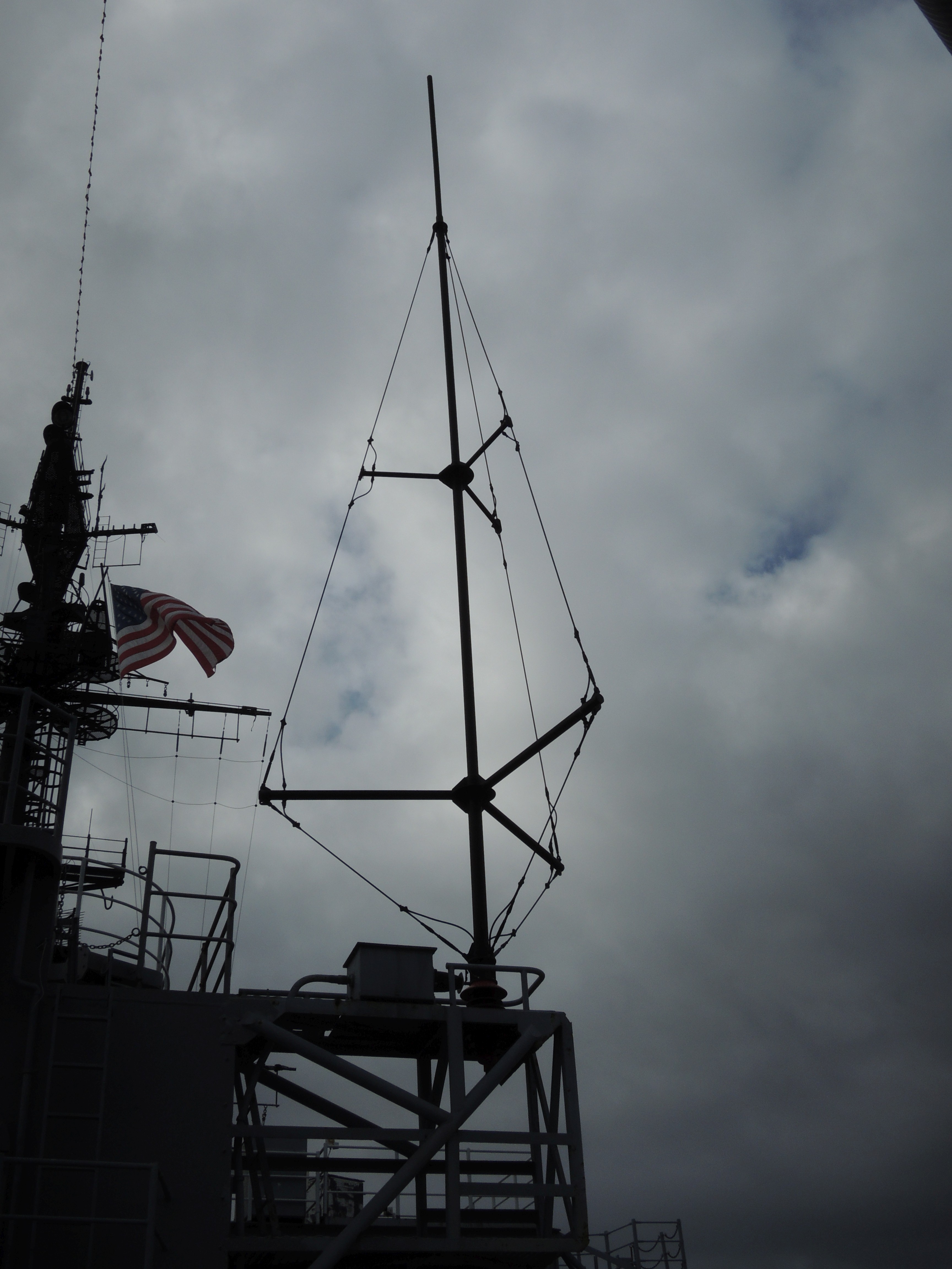
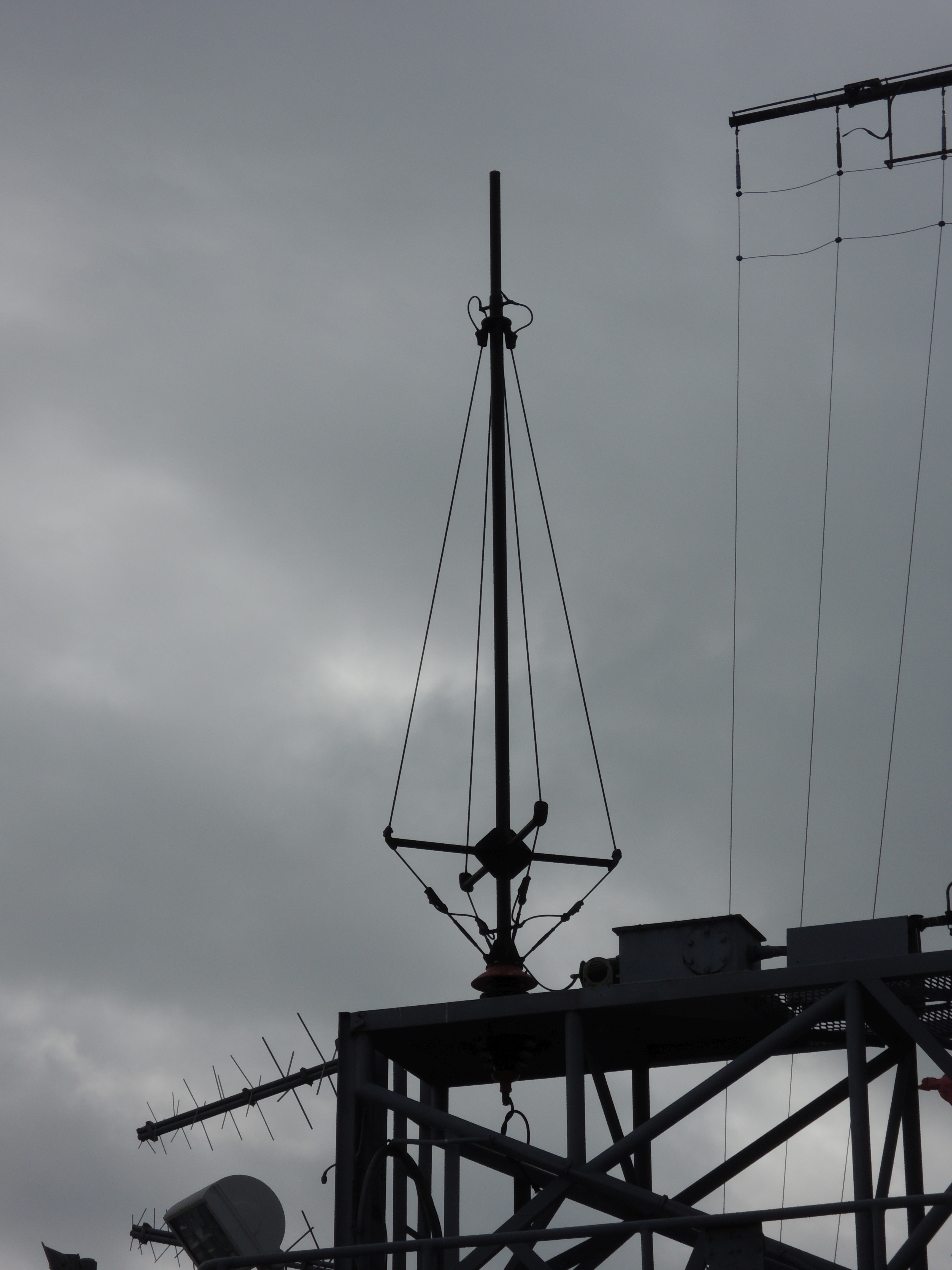
pole.(#2) Atop the former movie projector booth, on the fantail, is the Trussed Vertical. Installed during the 1980 modernization this was a transmit antenna but in 1987 was converted to a receive antenna. This change was due to concerns about High Energy Radiation near Ordinance (HERO). In other words, radio signals could have ignited weapons located onboard the helicopters.
(#3) On the starboard side of the 03 level, near the forward ABLs (Tomahawk Missiles) is the Twin stubs antenna. This antenna replaced the transmit antenna lost by the HERO concerns on the fantail.
(#4) At the 05 level Open Bridge is a good example of the base color coding mentioned above. On the Port side, near the CWIS is a red colored 35 foot vertical transmitting antenna while on the starboard side is another 35 foot vertical, blue base, used by the ship's receivers. On the 05 level notice that the Twin Verticals just forward of the Fire Control Tower are also blue.
(#5) The least noticed of the BB-62 radio antennas is the Twin Fan antenna strung between the Aft Yardarm and the Aft Stack. These six almost horizontal wires are connected to a box on the top foremast via two red insulators.
(not shown) Four antennas that raise eyebrows are the "eggbeater", satellite receive antennas (not shown on drawing). This set of four antennas was located around the ship so that at least one of them would always have sight of a Naval satellite used for Fleet Broadcasts. They are located at the following locations: one either side of the bridge; one at 07 level above the ship's bell; and one on the Aft secondary gun director.

1945 Antenna Plans - thanks to Dave AB5S
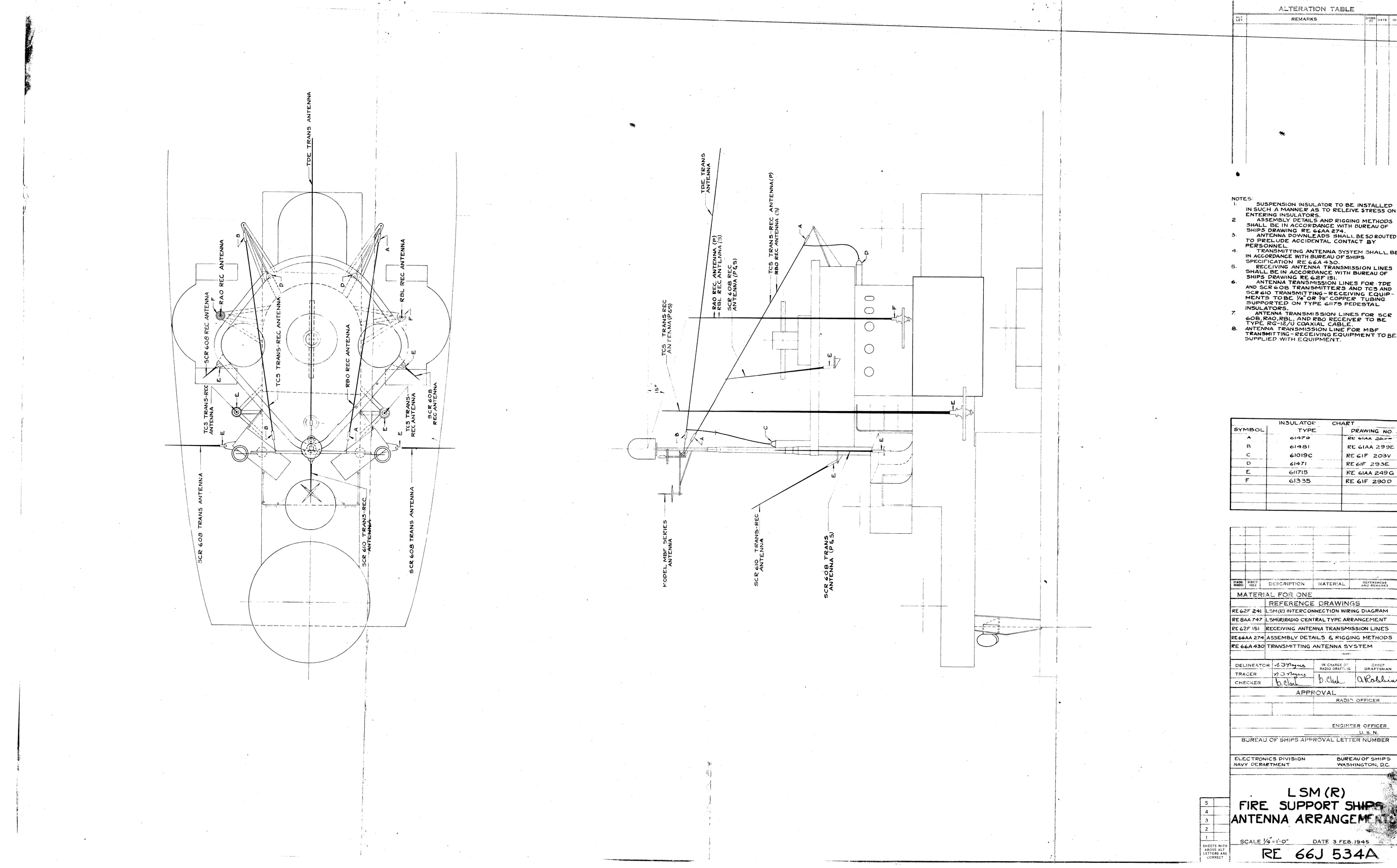
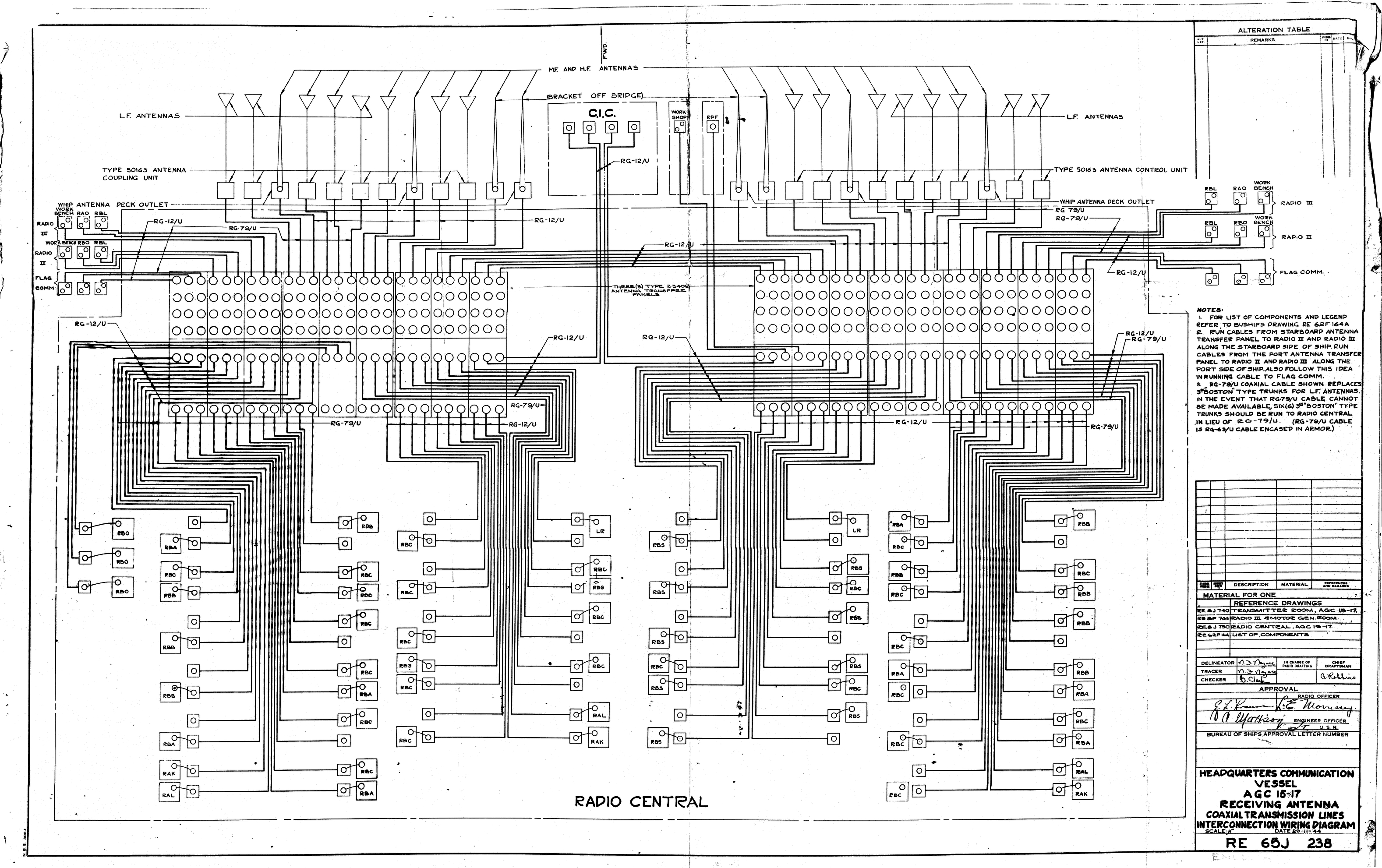
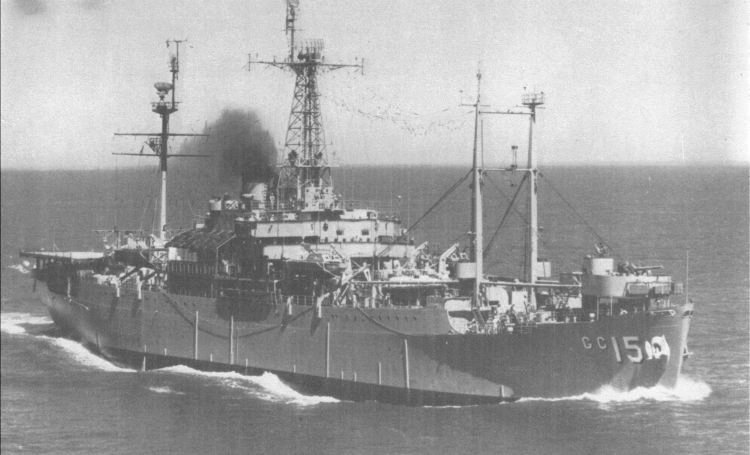
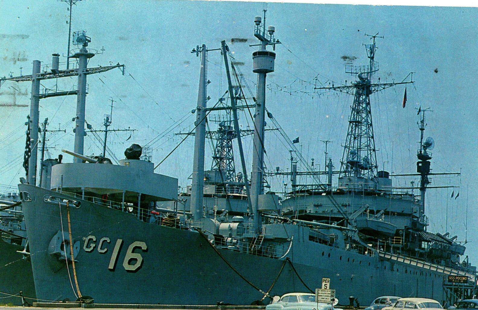
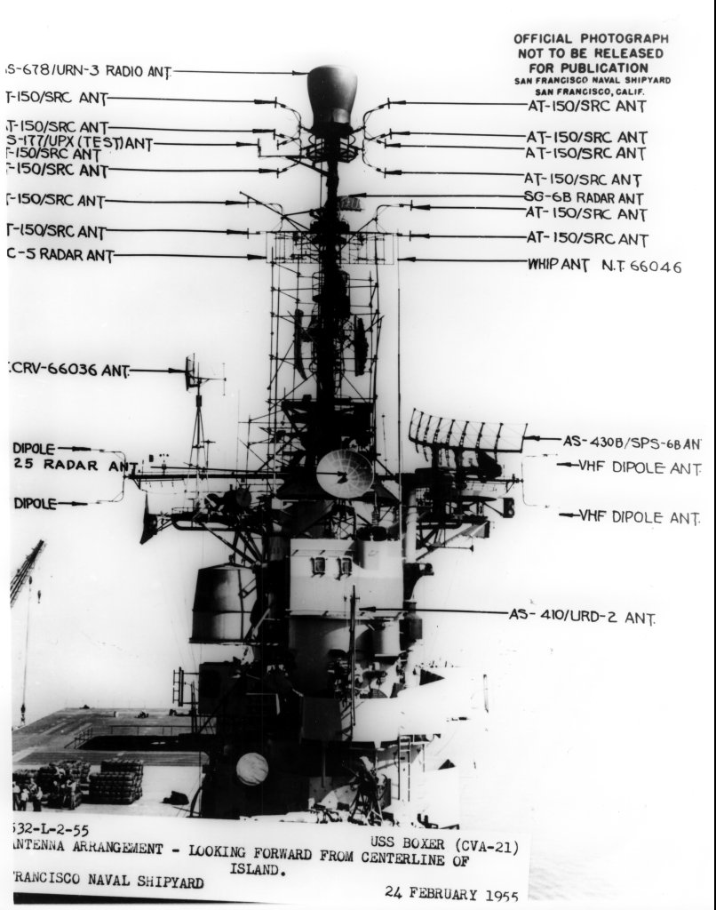
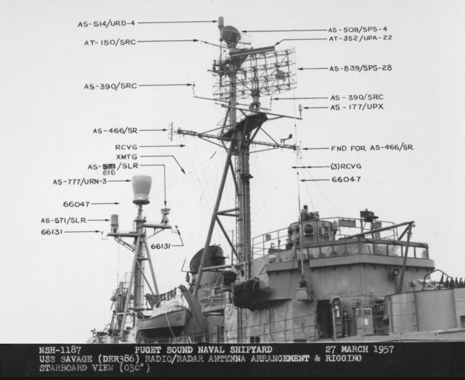
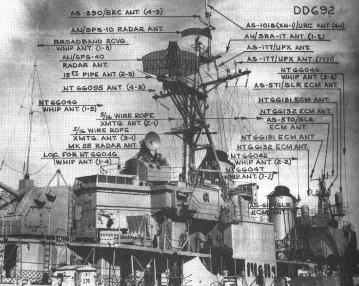
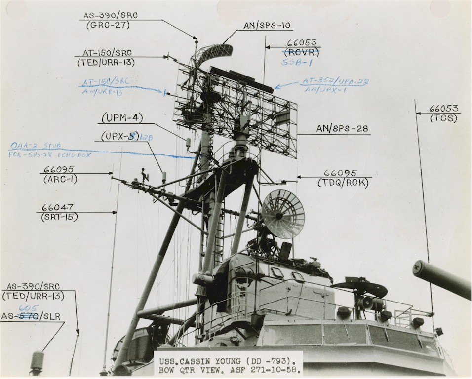
USS Adirondack AGC-15 - postwar
Shipyard photos from National Archives thanks to Navsource


ANTENNA & MULTICOUPLER SYSTEM ON THE DL-2 (1952)
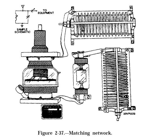
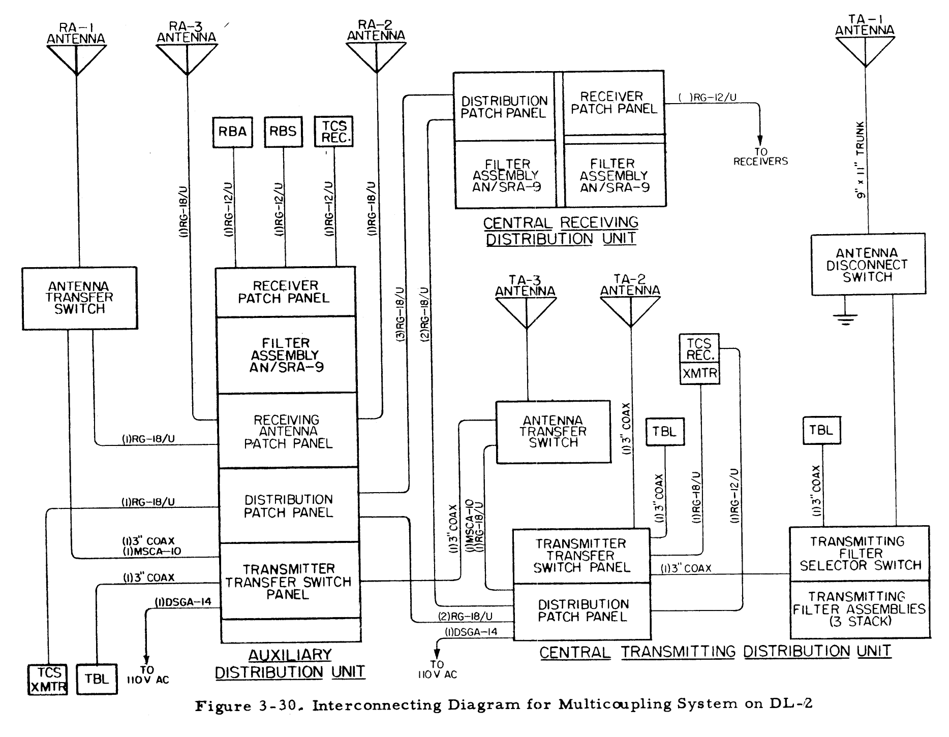 The multicoupling system to be installed on a new vessel,
the Destroyer Leader DL-2 is shown in Figure 3- 30. The communications
system on this ship uses a minimum number of antennas and is designed for
maximum flexibility.
The multicoupling system to be installed on a new vessel,
the Destroyer Leader DL-2 is shown in Figure 3- 30. The communications
system on this ship uses a minimum number of antennas and is designed for
maximum flexibility.
There are six antennas used with the multicoupling system: two 35 -foot whips and one wire antenna for receiving, and two 35-foot whips and one flat -top antenna for transmitting. The receiving antennas are located forward and the transmitting antennas are located aft so as to provide the best possible isolation between the two types. Provision is made to use any equipment with any of the antennas (except the flat-top) in the event of failure or damage to certain portions of the ship.
This ship uses three AN/SRA-9 receiving filter assemblies. Two located at the central Receiving Distribution Unit and one at the Auxiliary Distribution Unit.
Three transmitting filter assemblies are located at the Central Transmitting Distribution Unit. One of the filter assemblies, F-159/SRT has a crossover frequency of 375 kc with switching provisions for shifting the crossover frequency to 425 kc; another filter assembly, F-160/SRT has a crossover frequency of 1750 kc; the third filter assembly, F-161/SRT, has a crossover frequency of 3250 kc with provisions for shifting the crossover frequency to 3750 kc.
The three transmitting filter assemblies are stack-mounted. A four-pole, three-gang, Filter Selector Switch is mounted on the rear of the cabinets. The purpose of this switch is to allow both transmitters to be connected to any one of the three filter assemblies or to allow one of the transmitters to be connected directly to the antenna. This permits more versatile use of the transmitting equipments .
Antennas aboard USS Arlington AGMR-2 (thanks to John KX4P)
HF Communications Antennas
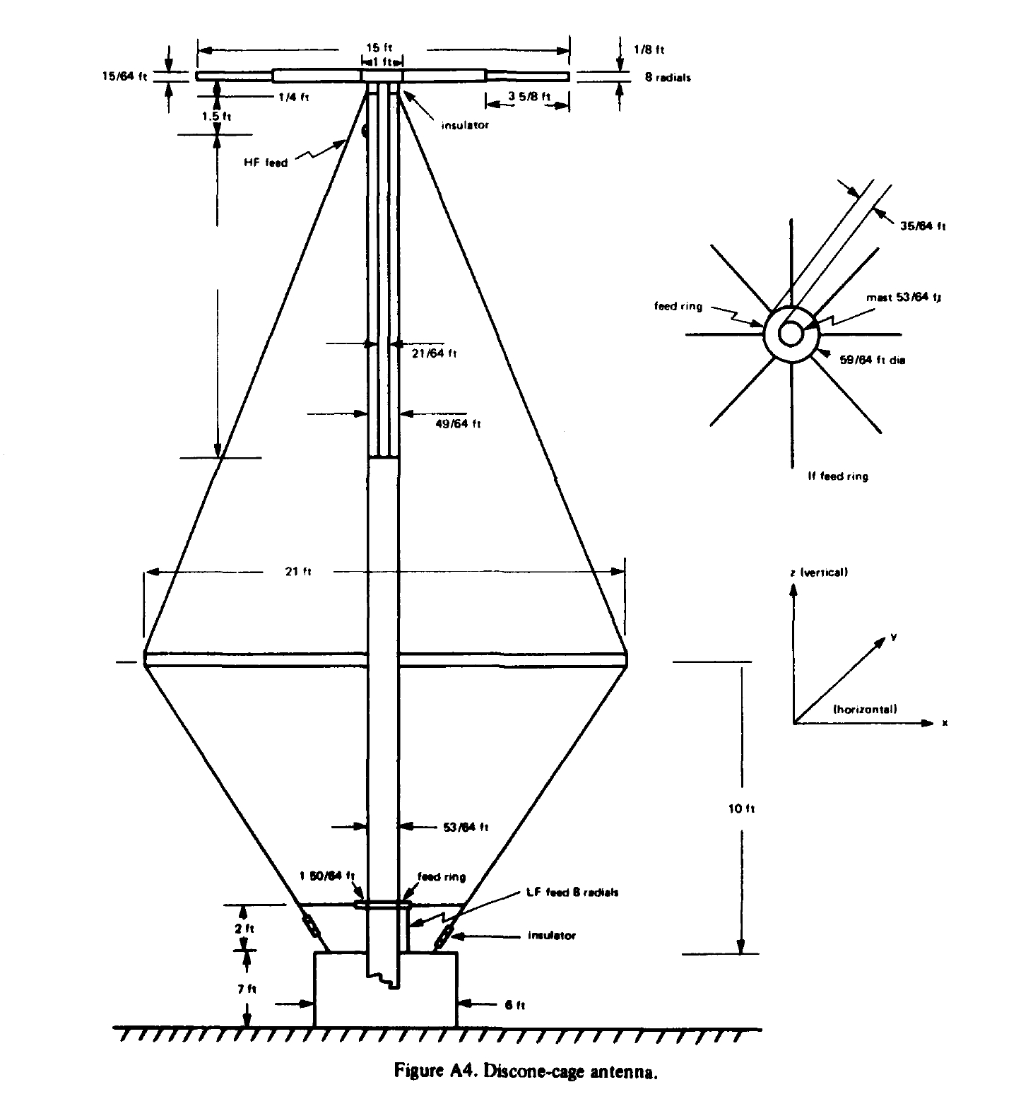
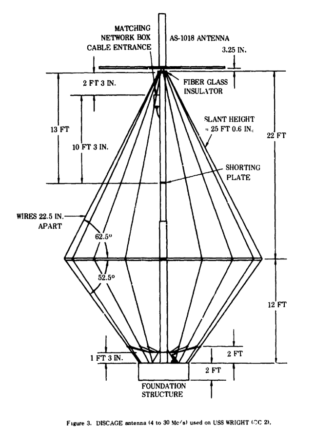
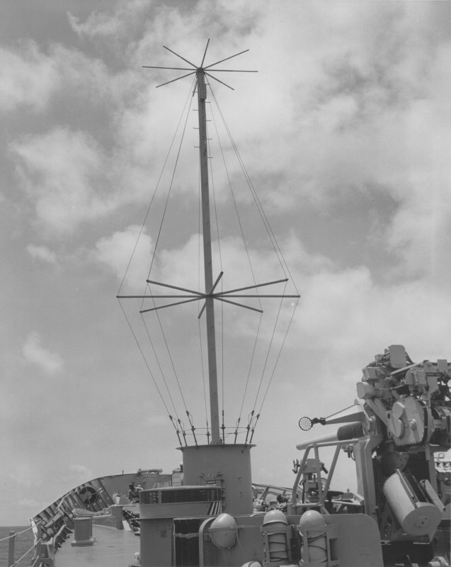
Discone-cage (Discage) Antenna
(USS Wright CC-2)
Bow Discone-Cage Antenna
(USS Los Angeles CA-135)
- Article on discage design
- Good photo of Bow Discage on USS Canopus AS-34
- Discage & Whips aboard USS Hornet
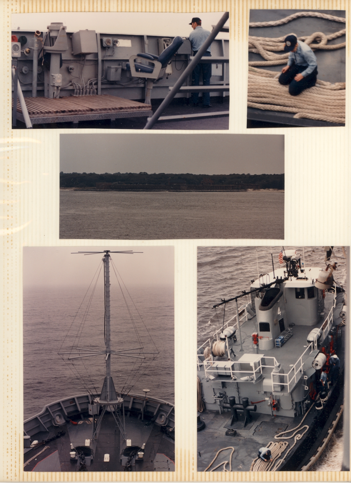
Bow Discone-Cage Antenna aboard USS Iowa BB-61
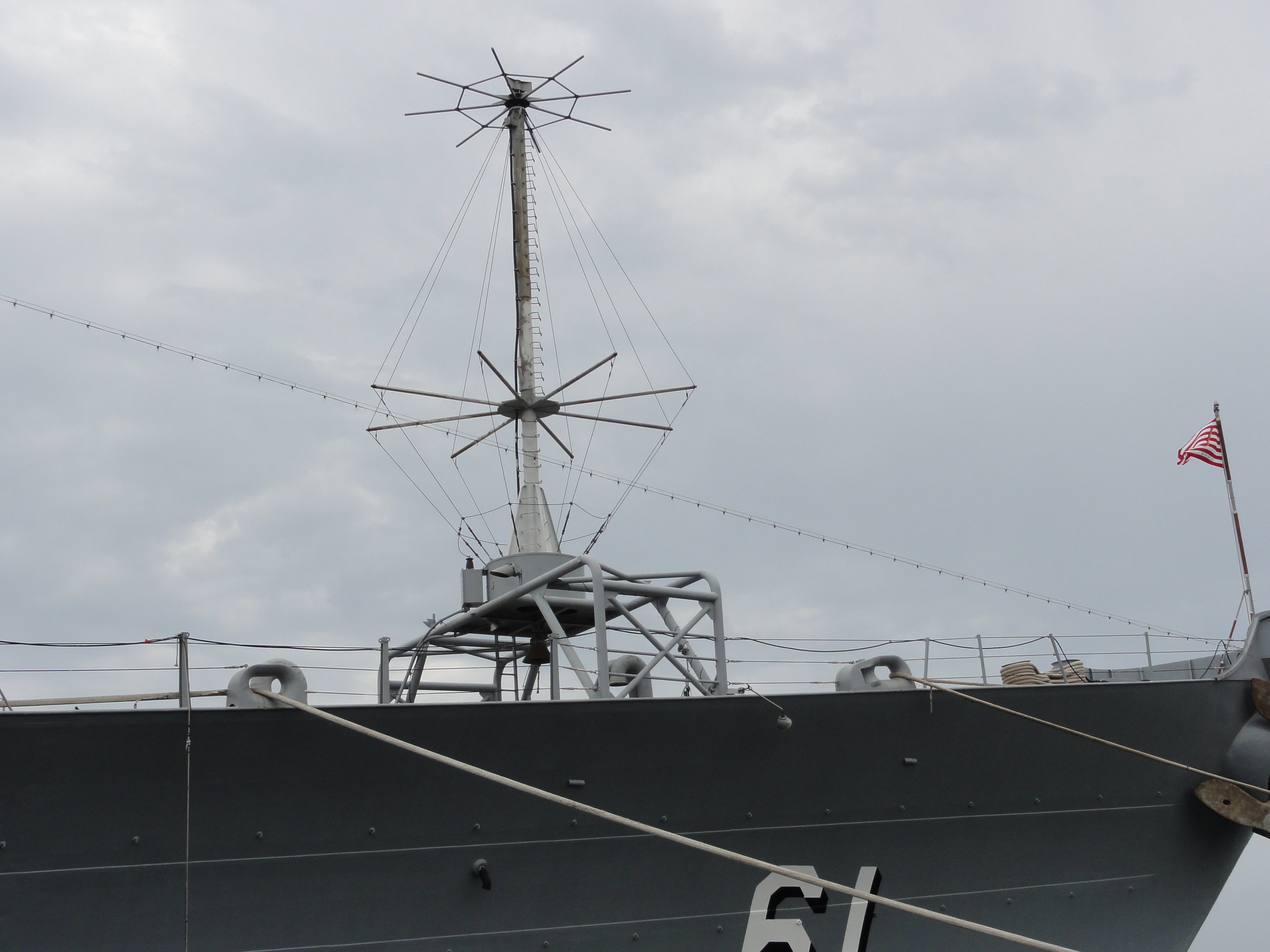
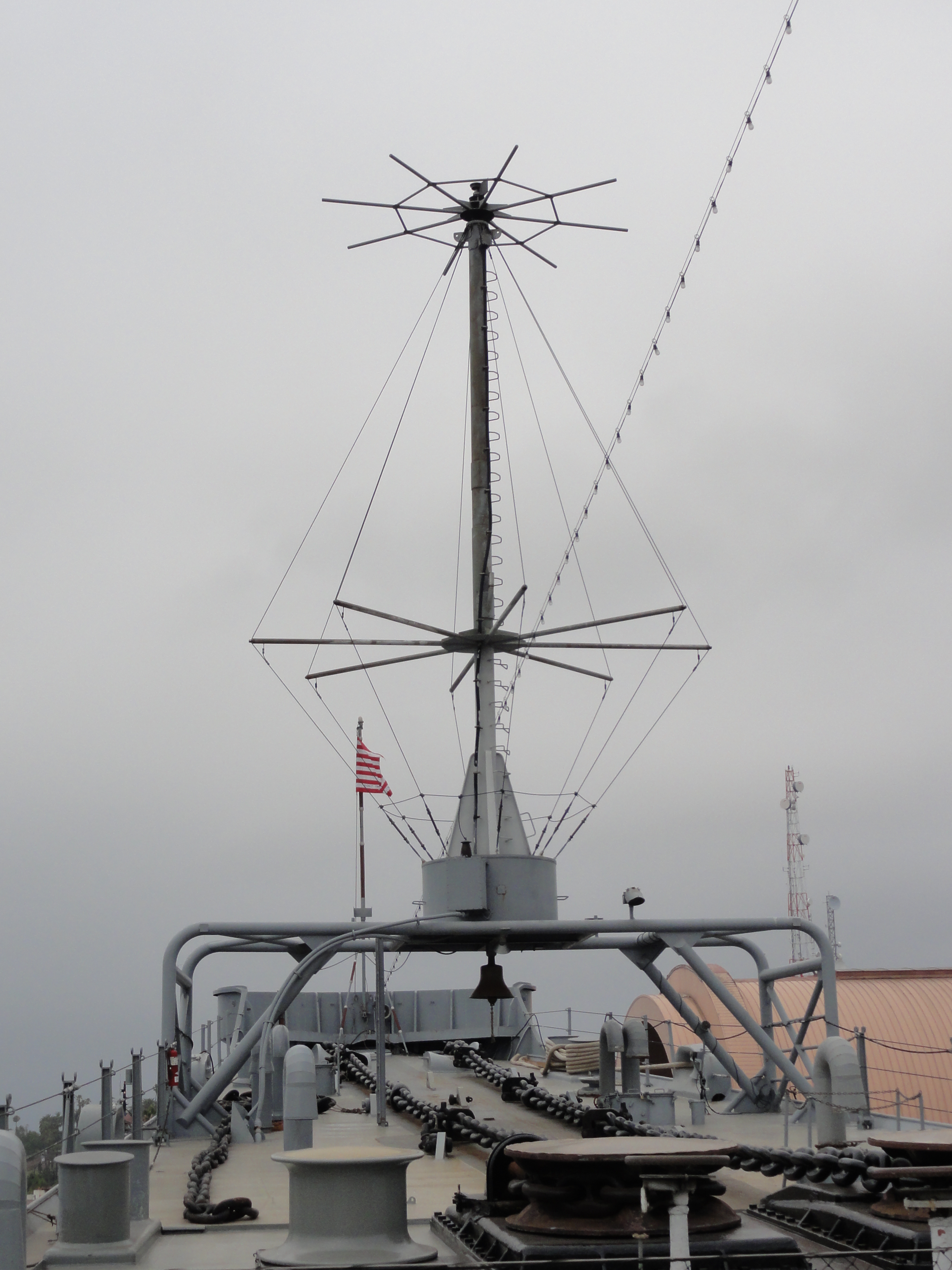
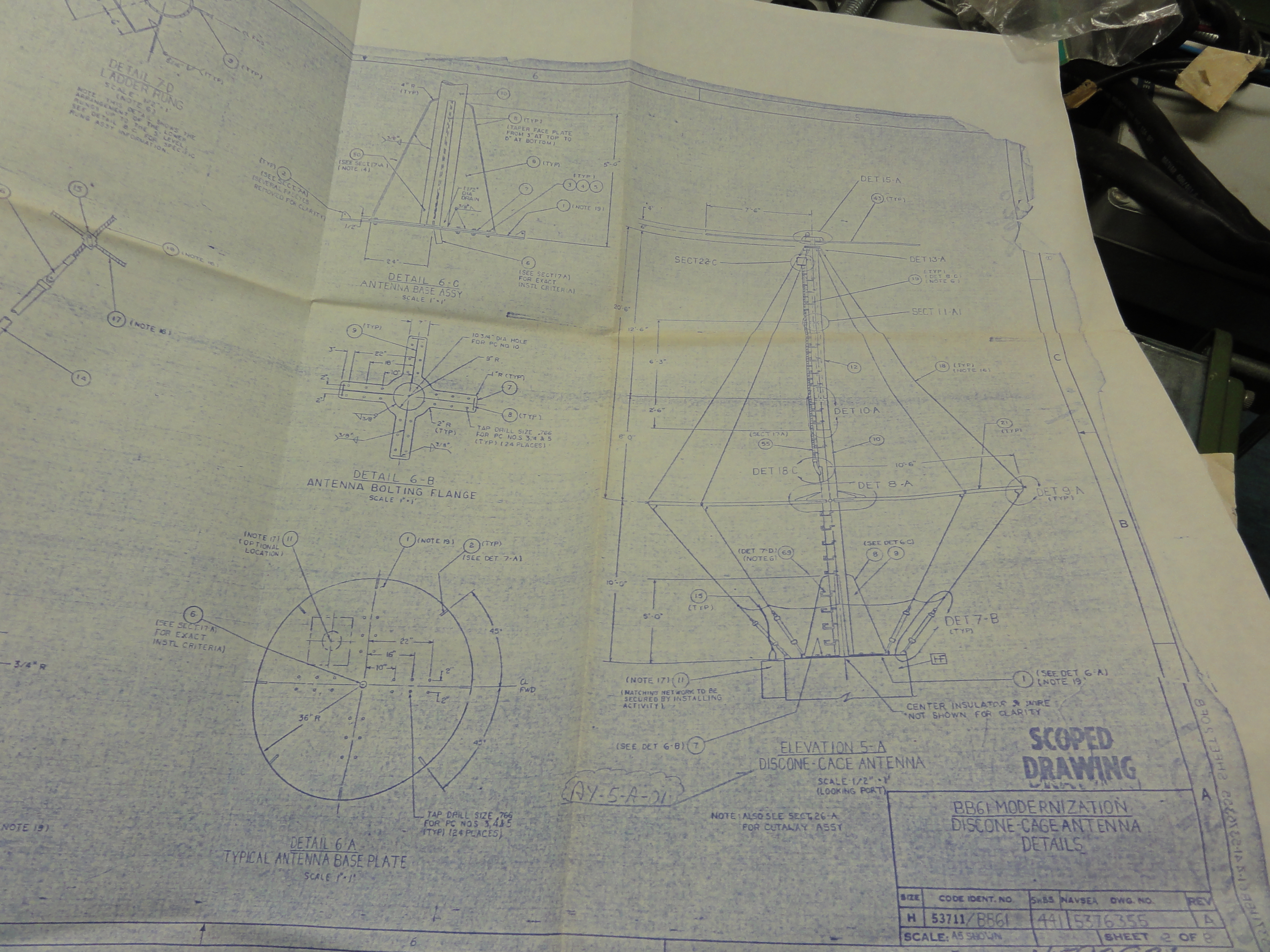
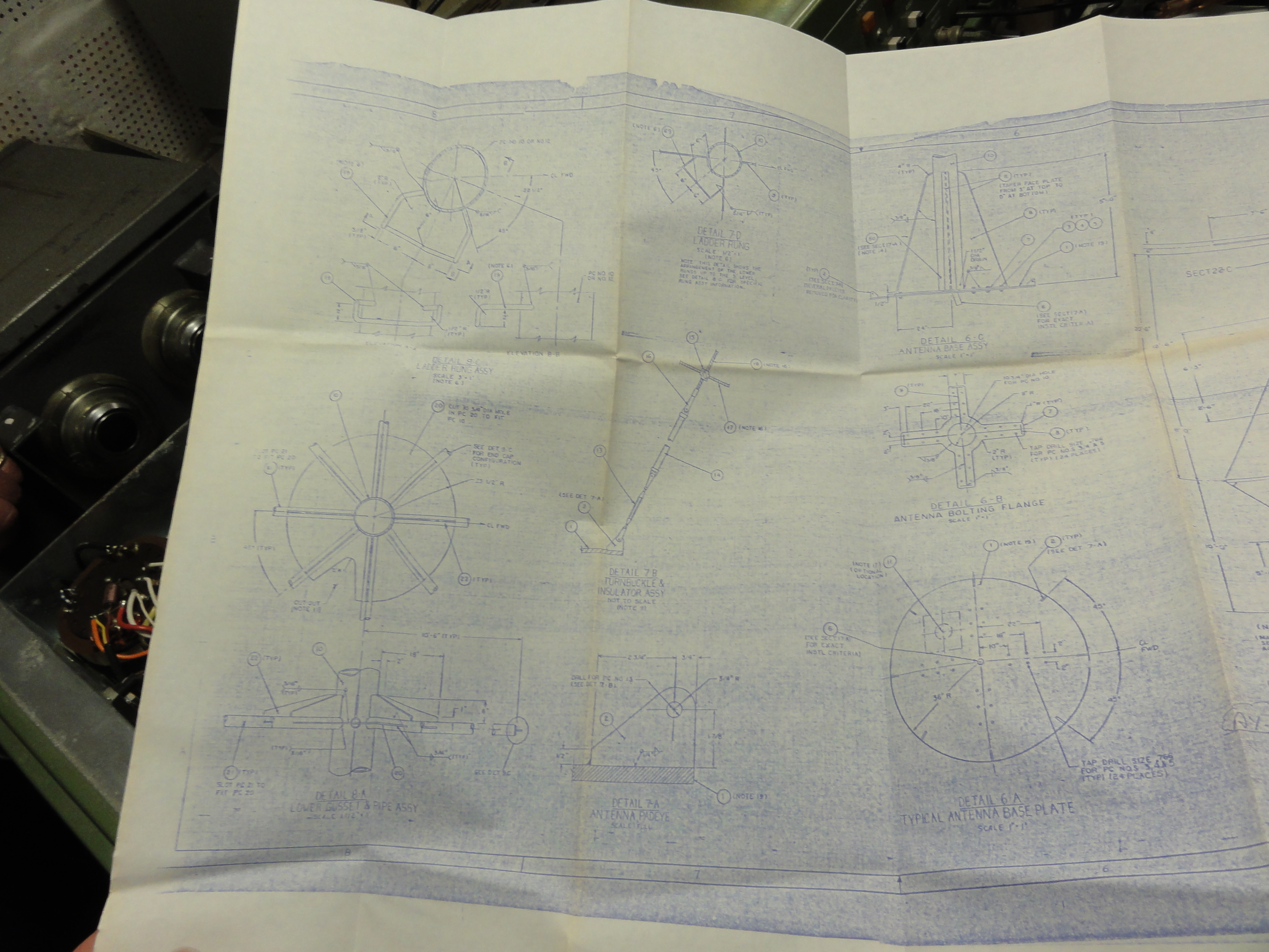
The discone-cage antenna is actually two antennas combined into one structure, each antenna having a separate feedpoint. The highband antenna is of the discone type, utilizing an array of radial elements in a horizontal plane at the top of the cage as the disc and the upper section of the cage as the cone. The antenna is fed at the gap between the disc and the apex of the cone. The midband antenna consists of the entire cage section. The lower ends of the wires which form the cage are terminated on a collector ring which is insulated from the grounded supporting structure and used as the feedpoint. Feedpoint impedance-matching networks are required for both sections. A shorted coaxial stub is built into the upper section of the supporting mast for matching the upperband discone antennas to 50-ohm coax. It is occasionally necessary to add a series capacitor in the feedline, depending on antenna configuration details and the influence of antenna siting parameters. The matching network for the cage section is located in a deck-mounted enclosure at the feedpoint.
The discone-cage antenna must be located in a clear area. Adjacent structure will alter its radiation pattern characteristics and feedpoint impedances. One of the most successful locations has been on the bow of ships other than carriers. To avoid interference with anchor-handling requirements, the discage has been successfully installed on a bridge structure erected over the anchor machinery area. In other installations the antenna has been mounted on a pedestal, approximately 7 feet high, to reduce the electrical shock hazard to personnel.
Well, that discone has been deteriorating over the years, especially its foundation, that the USS Missouri Memorial Association is seriously considering removing it. That would leave KH6BB with only a couple of verticals with which to make contacts. Considering how much better the discone works this would cause a serious decrease in the ability to contact KH6BB.
The members of KH6BB have made arrangements with the memorial association to try and raise funds to restore the discone antenna. The estimate for repairs is $45K along with our time and talent efforts. We are looking for any amounts large or small to keep our signal on the air. More details are available at http://www.ussmissouri.org/
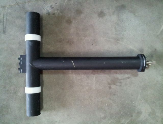
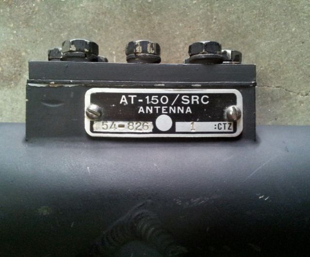
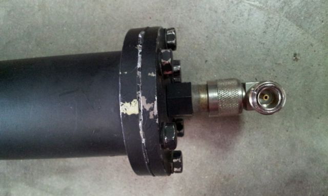
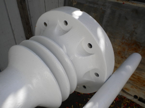
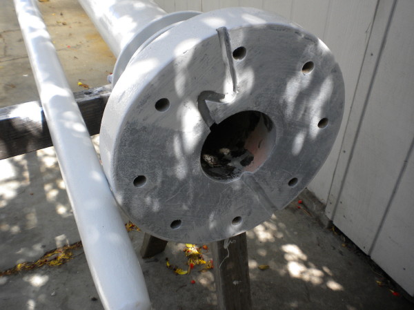
Shipboard Sleeve Antennas
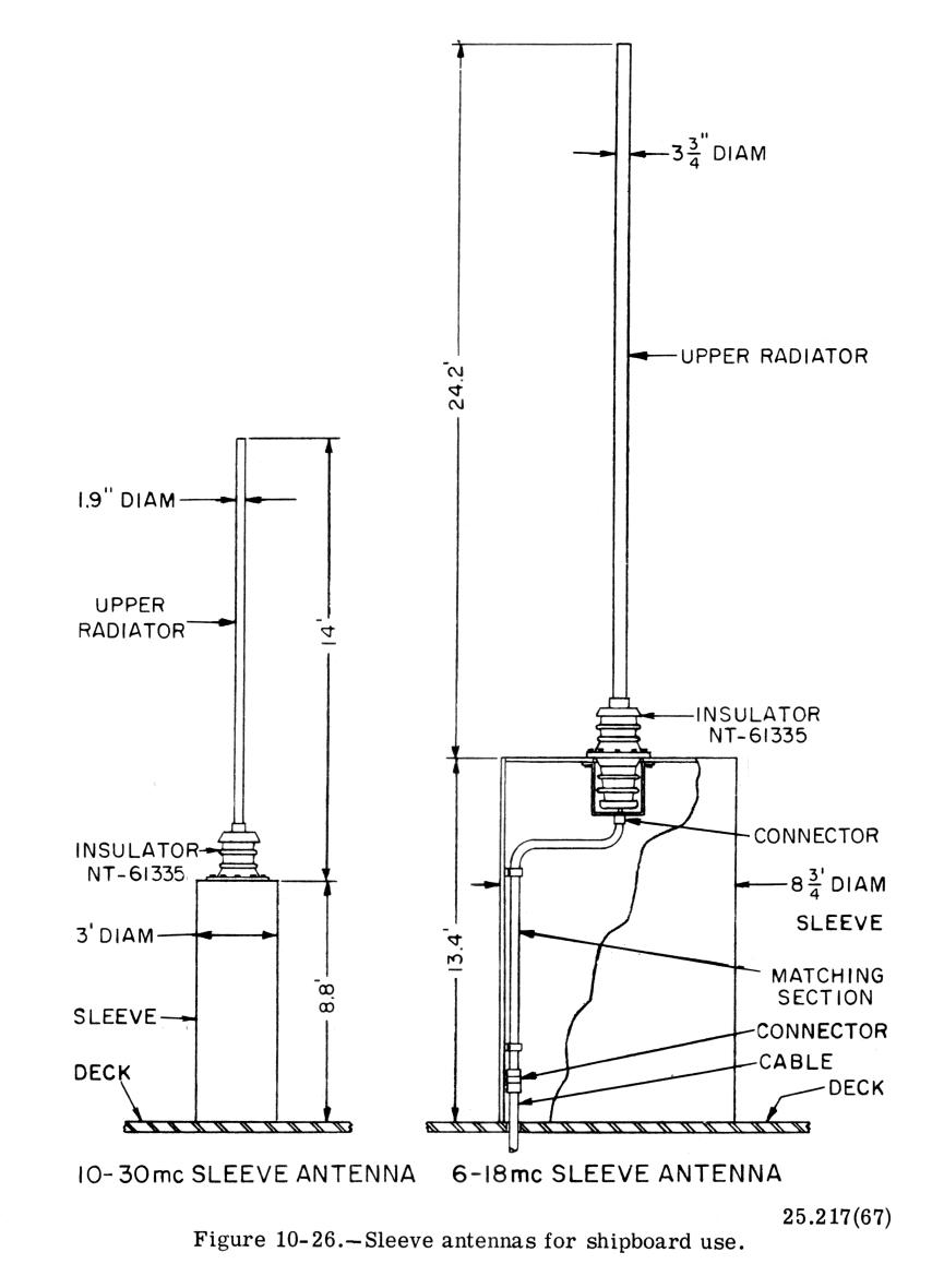
Another broadband antenna used extensively is the conical monopole shown in figure 3-36. Like the sleeve antenna, it is used both ashore and aboard ship. When operating at frequencies near the lower limit of the high-frequency band, the conical radiates in much the same manner as a regular vertical antenna (omnidirectional on the horizontal plane). At the higher frequencies the lower cone section radiates, and the effect of the top section is to push the signal out at a low angle. The low angle of radiation causes the skywave to return to the earth at great distances from the antenna. Hence, the conical monopole antenna is well suited for long distance communication in the high-frequency range.
Wire Antennas - Also See wire antenna hardware
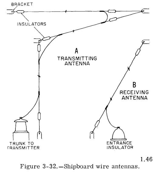
Shipboard Wire Antennas
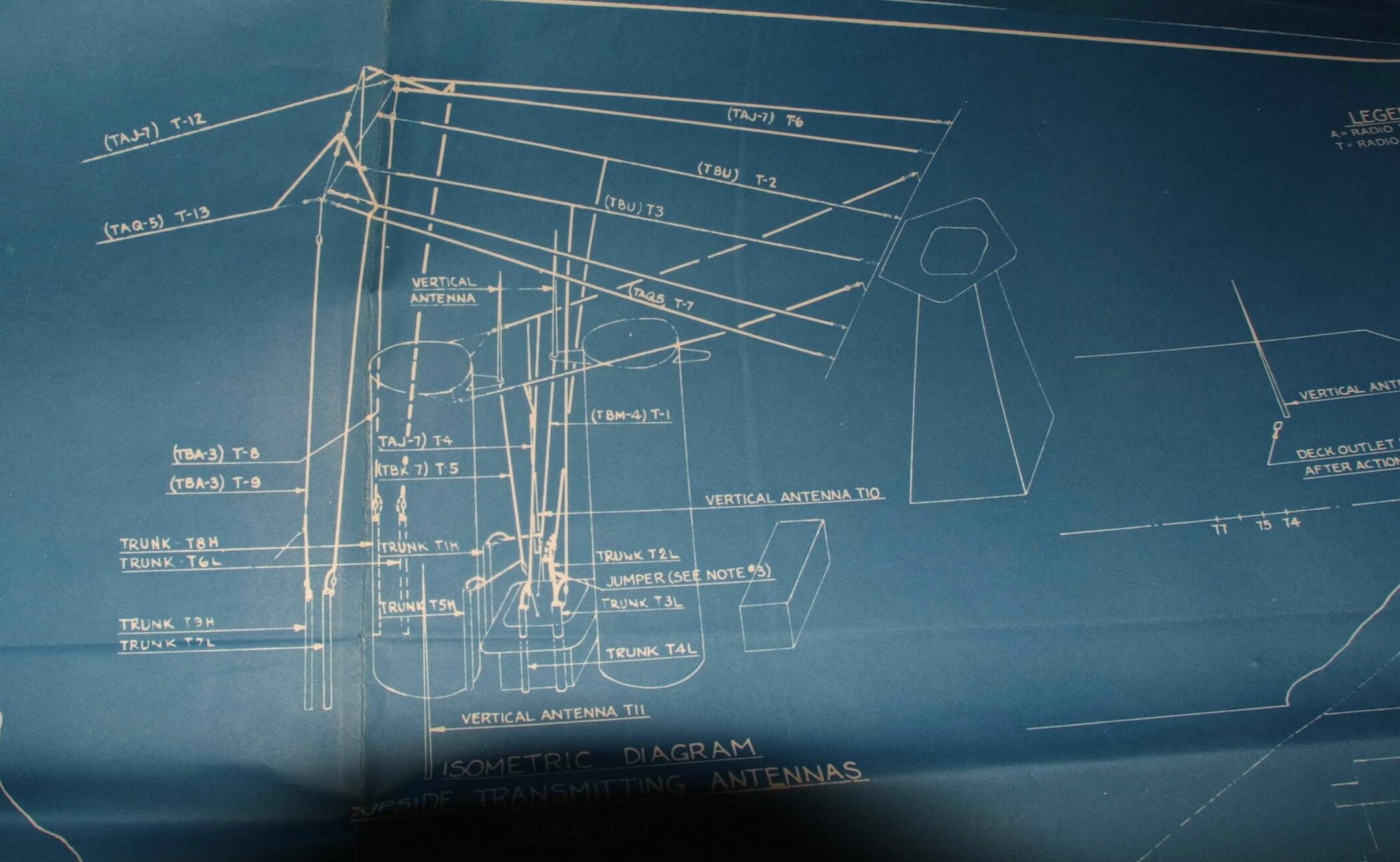
Blueprints of USS North Carolina BB-55 Wire Antennas


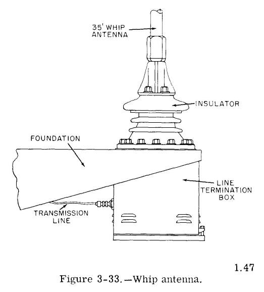
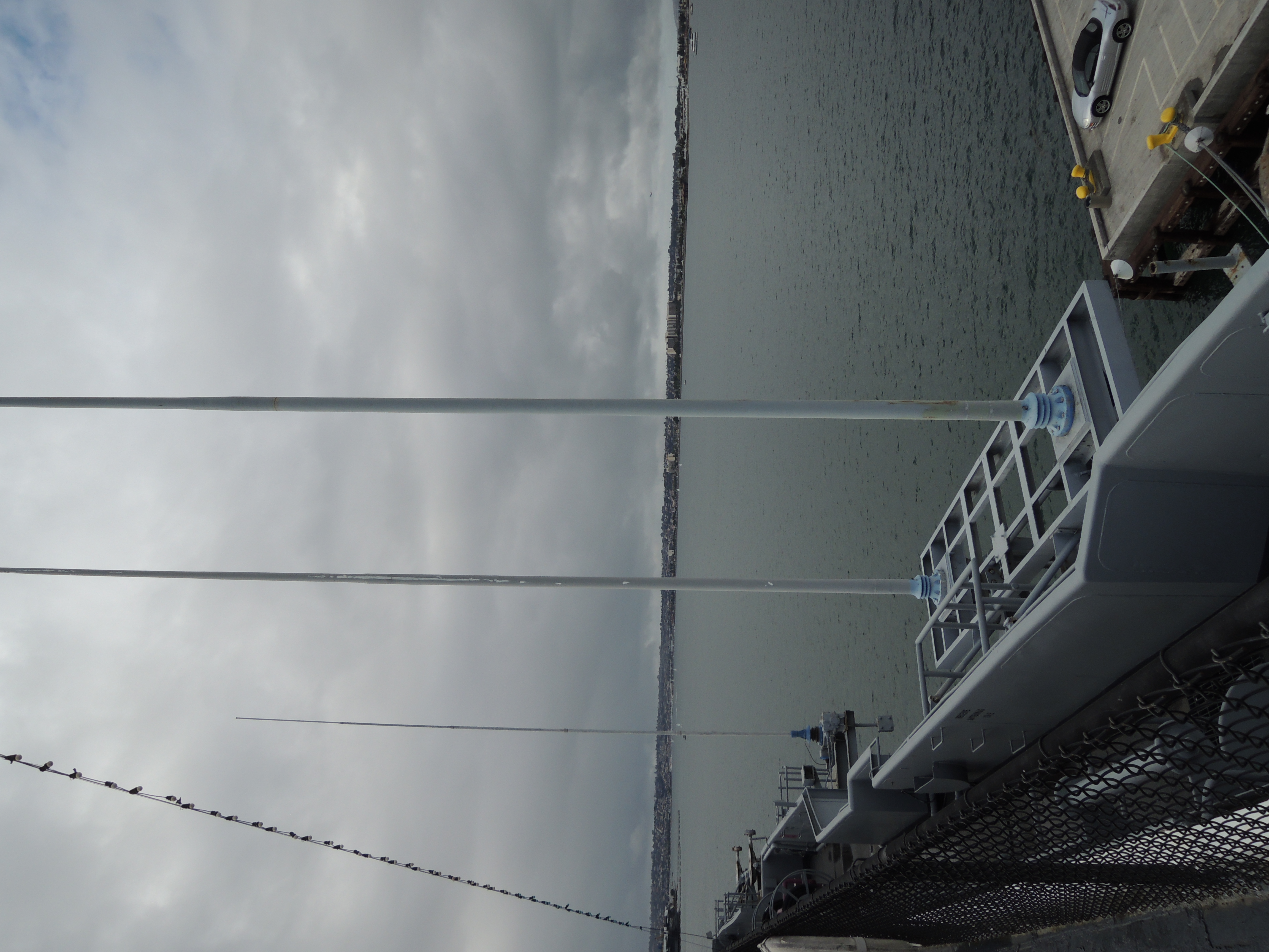
Whip antennas -
NT-66047 5 section, 35'
NT-66046 4 section, 28'
non-telescoping aluminum whip
more info
here
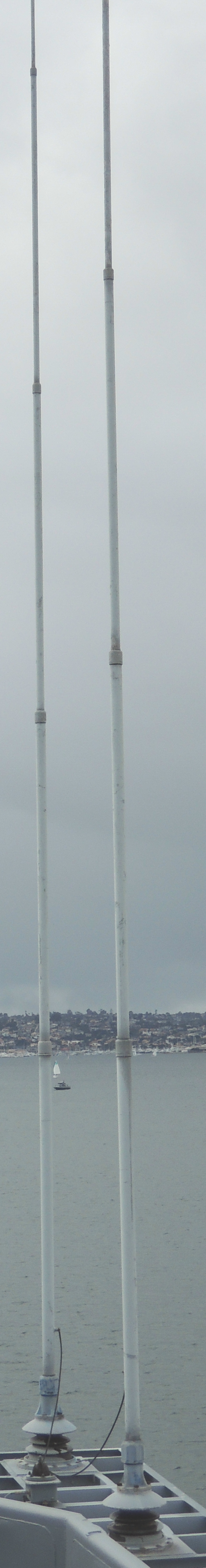
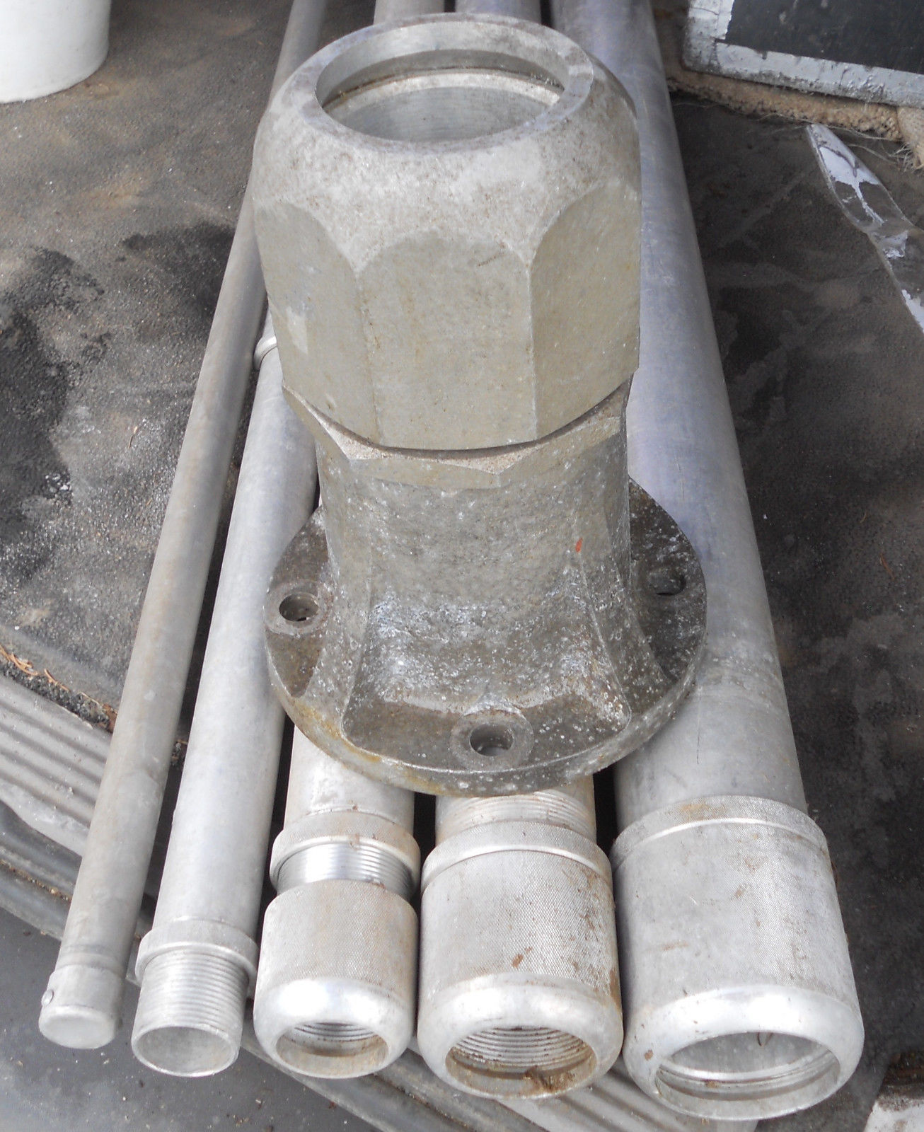
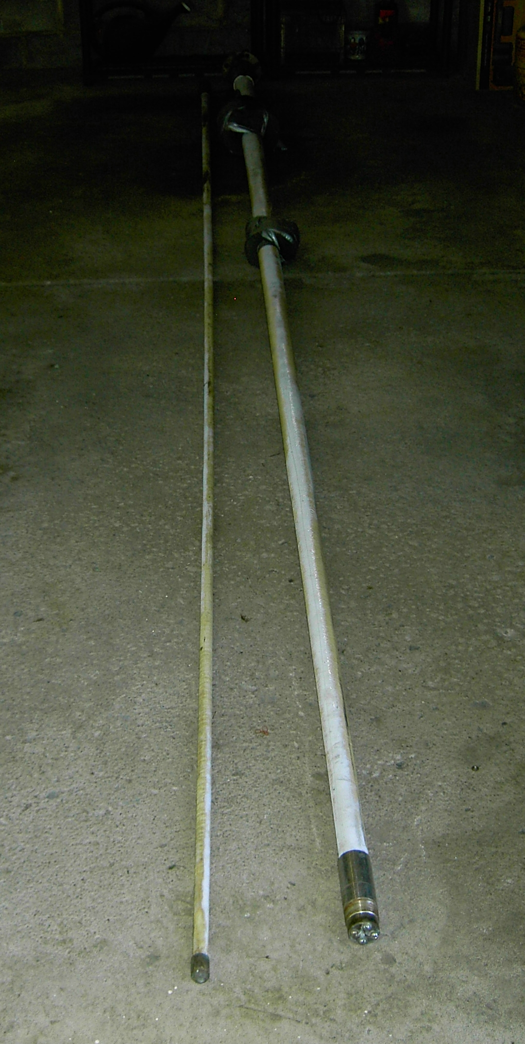
The NT-66047 is a 35-ft aluminum whip antenna composed of five equal lengths of 6061-T6 aluminum tube.
The lengths are joined together by fitting the adaptor sleeve at the bottom of the upper pieces into the larger diameter lower pieces and securing the joint with a threaded cap and lock nut.
NT-66047 35' whips aboard USS Midway CV-41
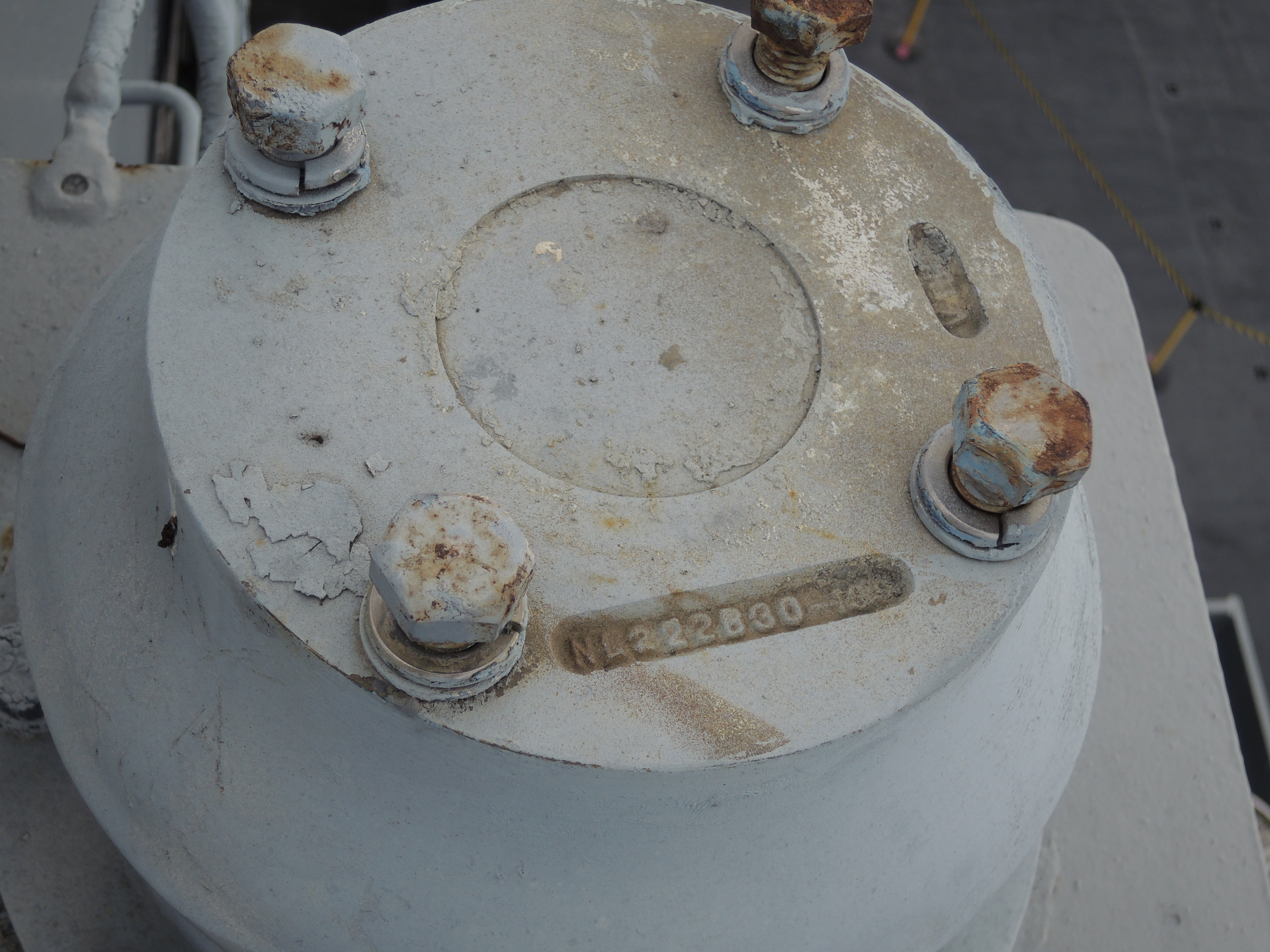
Mounting insulator for NT-66047 is
NT-61335 or NT-61350
(IL-18/U or IL-19/U)
(NL222B31-203 or NL222B32-240)
Whip mount atop insulator

NT-66053 is a general purpose 25' non-telescoping whip antenna
weighing 30 lbs. It consists of three sections of stainless steel
tubing which screw together. In shipboard installations, the whip
mounts on Base Insulator NT-61428. In submarines Insulator Type
NT-61664B is used.
The NT-66047 is a 35-ft aluminum whip antenna composed of five equal lengths of 6061-T6 aluminum tube. The lengths are joined together by fitting the adaptor sleeve at the bottom of the upper pieces into the larger diameter lower pieces and securing the joint with a threaded cap and lock nut.


AT-1022/SR - need photo
The AT-1022/SR is a 35-ft fiberglass whip antenna composed of two
sections approximately equal in length.
The antenna is uniformly tapered from an outside diameter at the base of
5-1/2 inch into an outside diameter at the top of 1-1/2 in.
fiberglass 35 ft. whip antenna
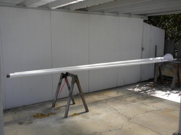
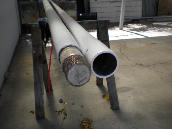
NT-66047 was replaced by a 2-section 35' fiberglass whip AS-2537/SR
(see photos at right & below)
The AS-2537 is made in two fiber-glass sections bolted together with an integral mounting base of steel included in the lower section. The radiating portion of the antenna consists of six beryllium-copper strips laminated in fiber glass. In the AS-2537A, the two whip sections screw together and the insulator portion is also fiber glass.

USS Midway CV-41 -
near whips NT-66047
far whips AS-2537/SR

Dual-Whip antenna -
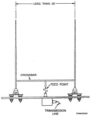
This antenna consists of two AS-2537/SR whips mounted approximately 10 feet apart, tied together at or near their feedpoints, and fed with a single coaxial feedline. The impedance characteristics in a 50-ohm system are greatly improved over those of a single whip. A matching network is required when the antenna is used for transmitting but is optional for receiving. The twin-whip antenna is normally located on top of the pilot house, sometimes tilted 45 degrees towards the bow. The best location is on the centerline.
AS-4037/SRC twin whip on the fantail of USS Antietam CG-54
06/07/1987

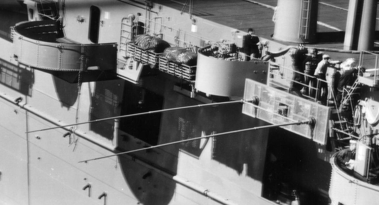

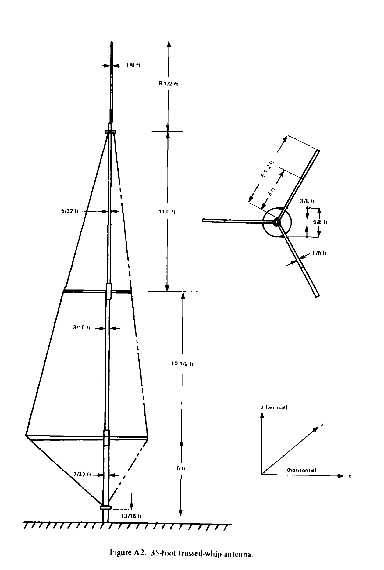
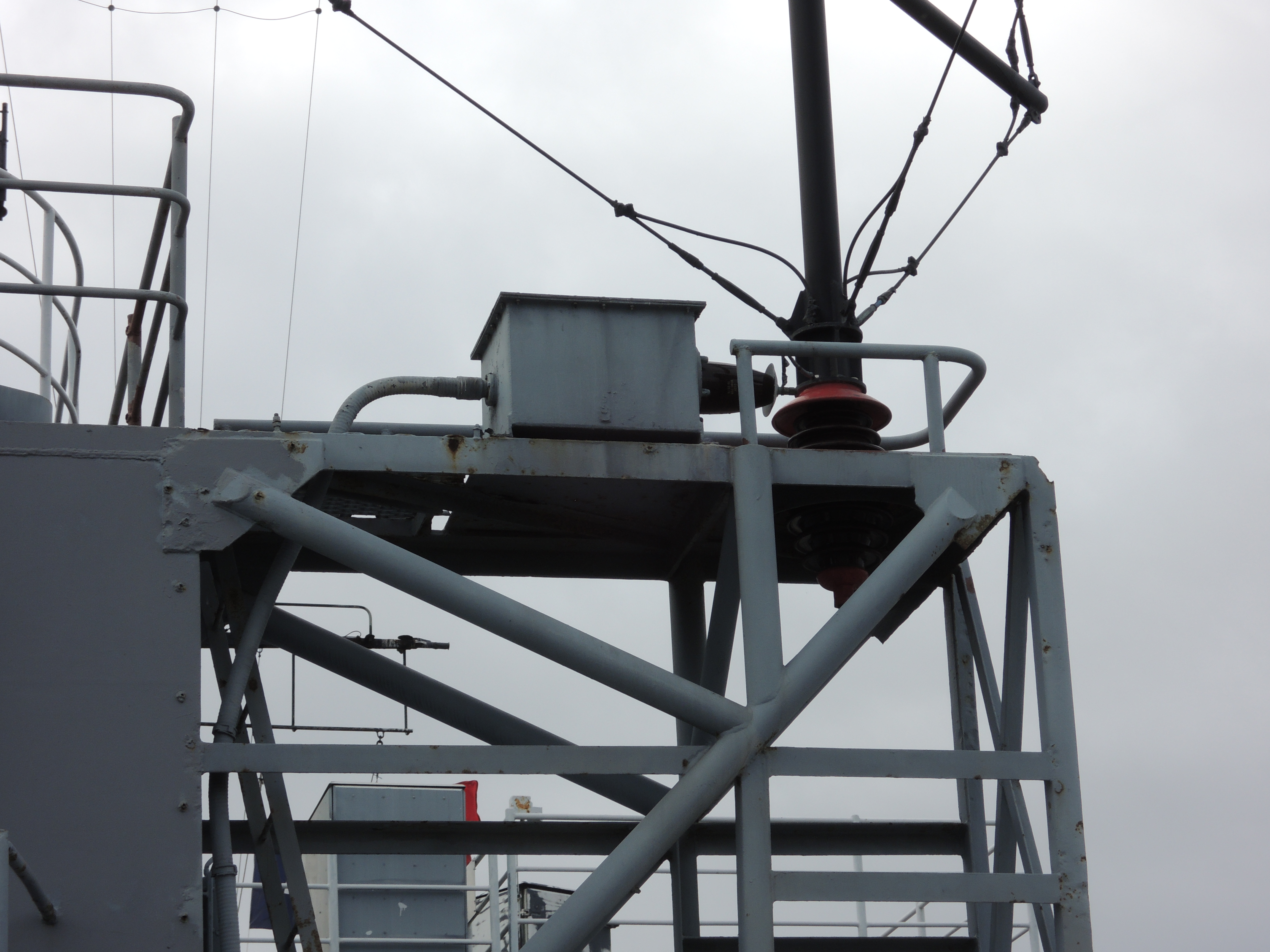
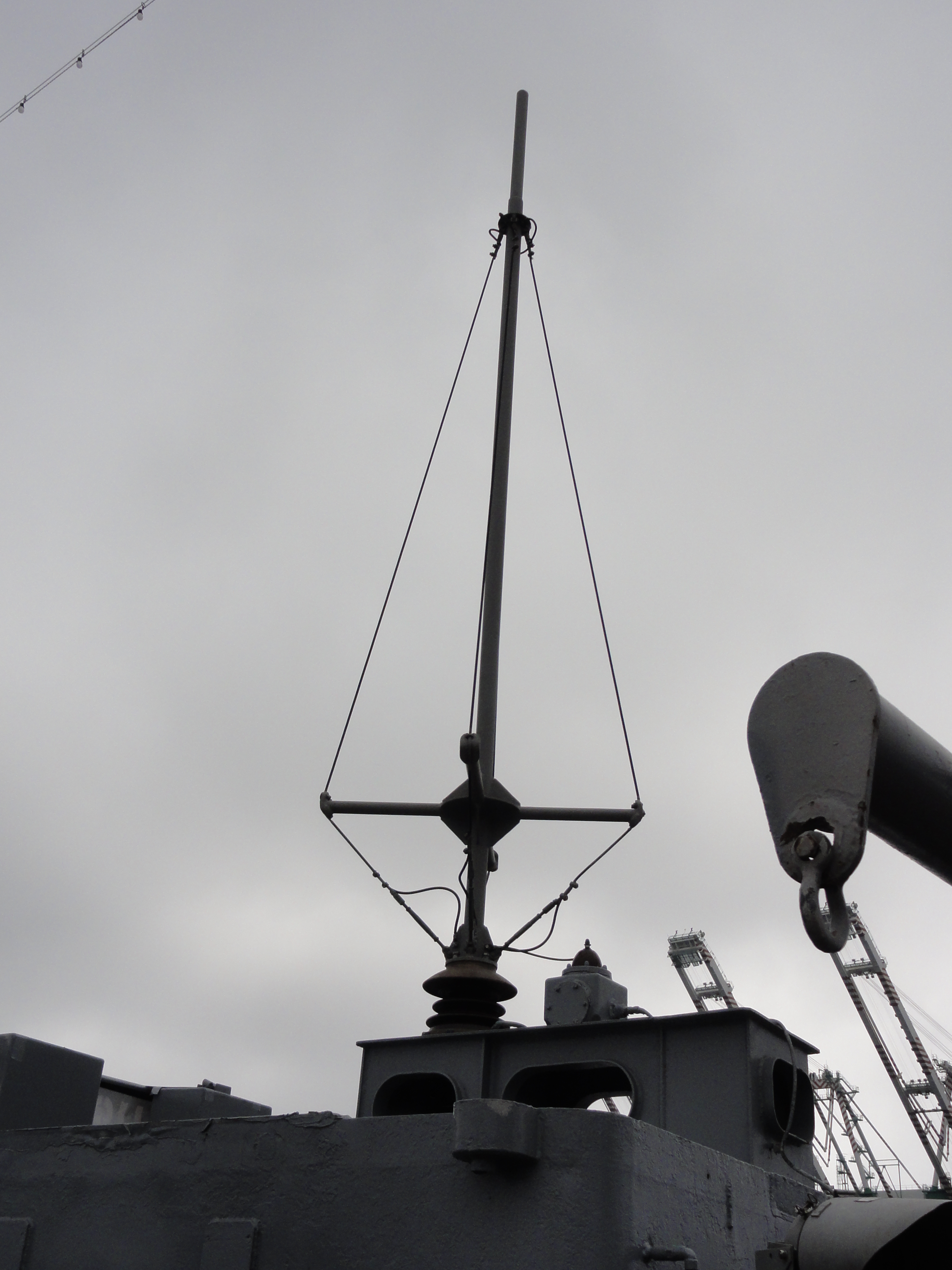
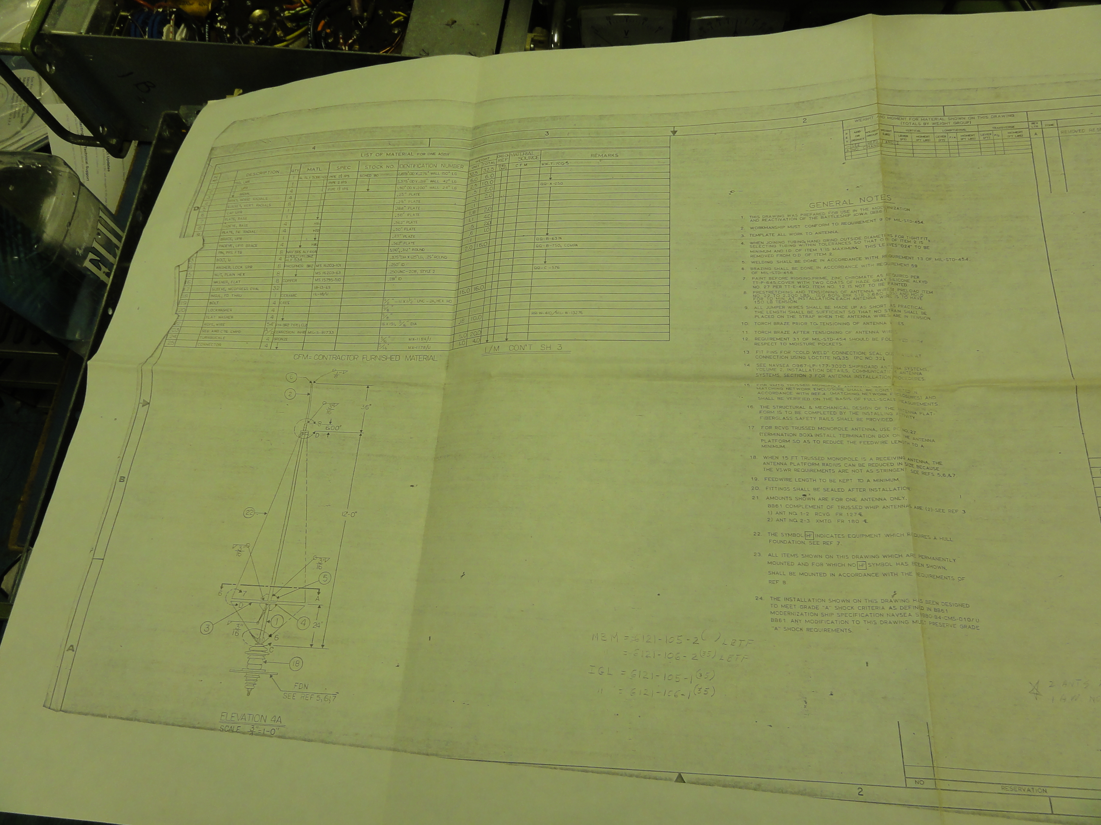
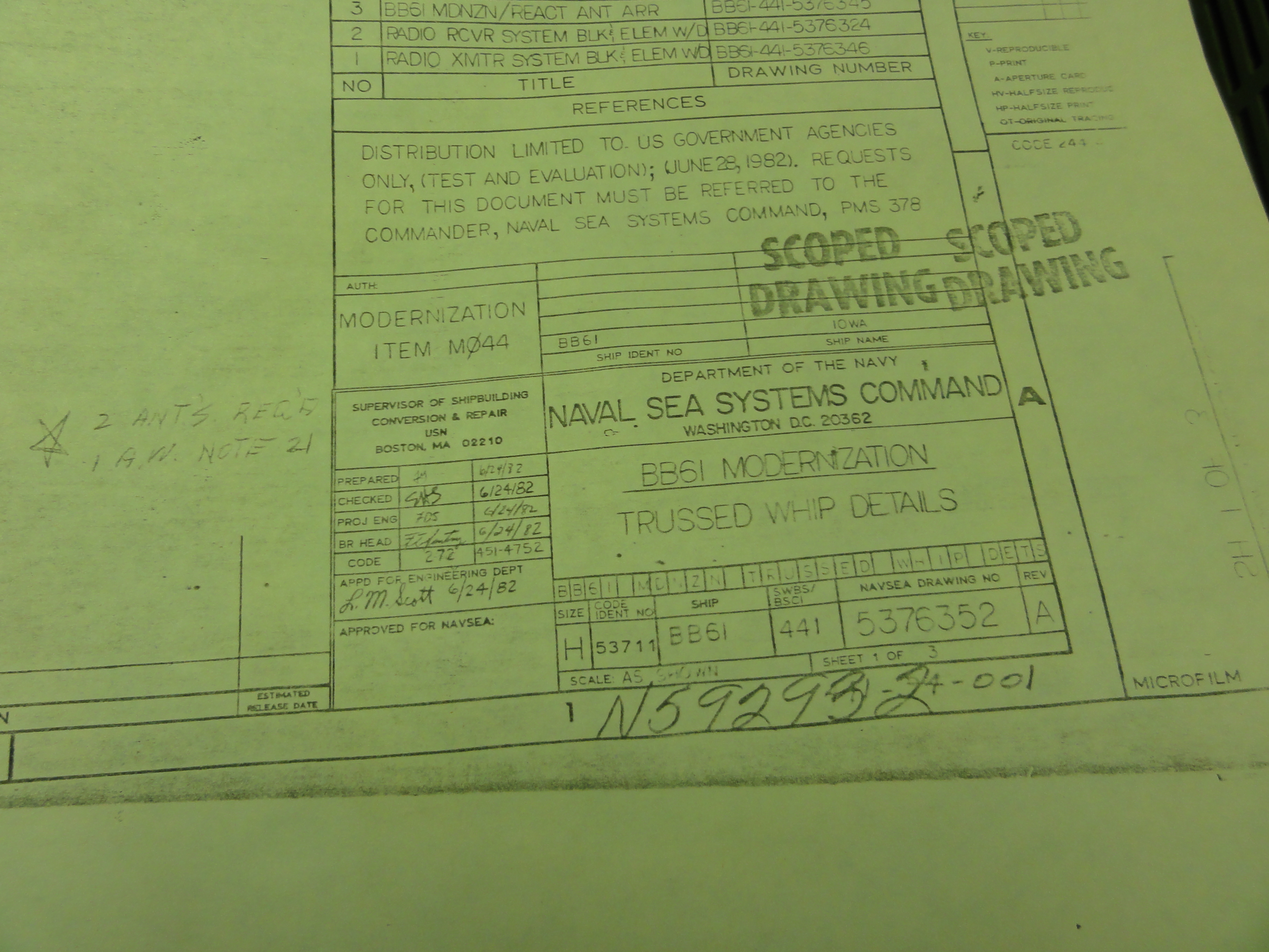
Trussed Whip Antennas -
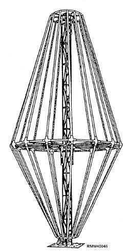
The 35-foot trussed whip is an NT-66047 or other type whip which has been broadbanded by the addition of wires around the antenna usually trussed to spokes attached part way up the whip (ref drawing below ). The diameter of the whip is increased to several feet (the diameter will vary) at the spokes with the wires tapering to the whip diameter at the bottom and upper attachment points of the trussing. Trussing improves the efficiency of a whip by lowering the mismatch loss to a 50-ohm system at the lower high frequencies.
(AS-2807 is the untrussed version)

AS-1857/SRA-43 Whip (5')
TN-438/SRA-43 Tuner
C-6828/SRA-43 Control
LF/VLF Communications Antennas - see also shipboard LF/VLF transmittting antennas
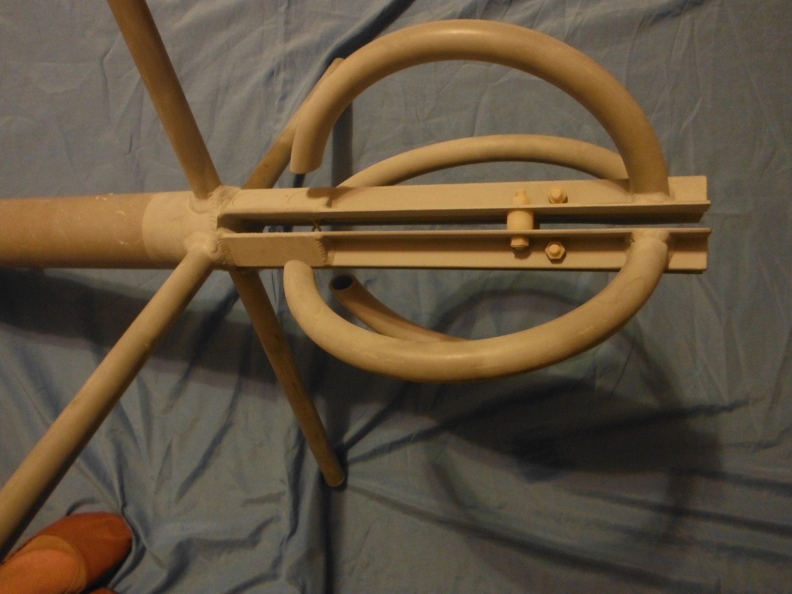
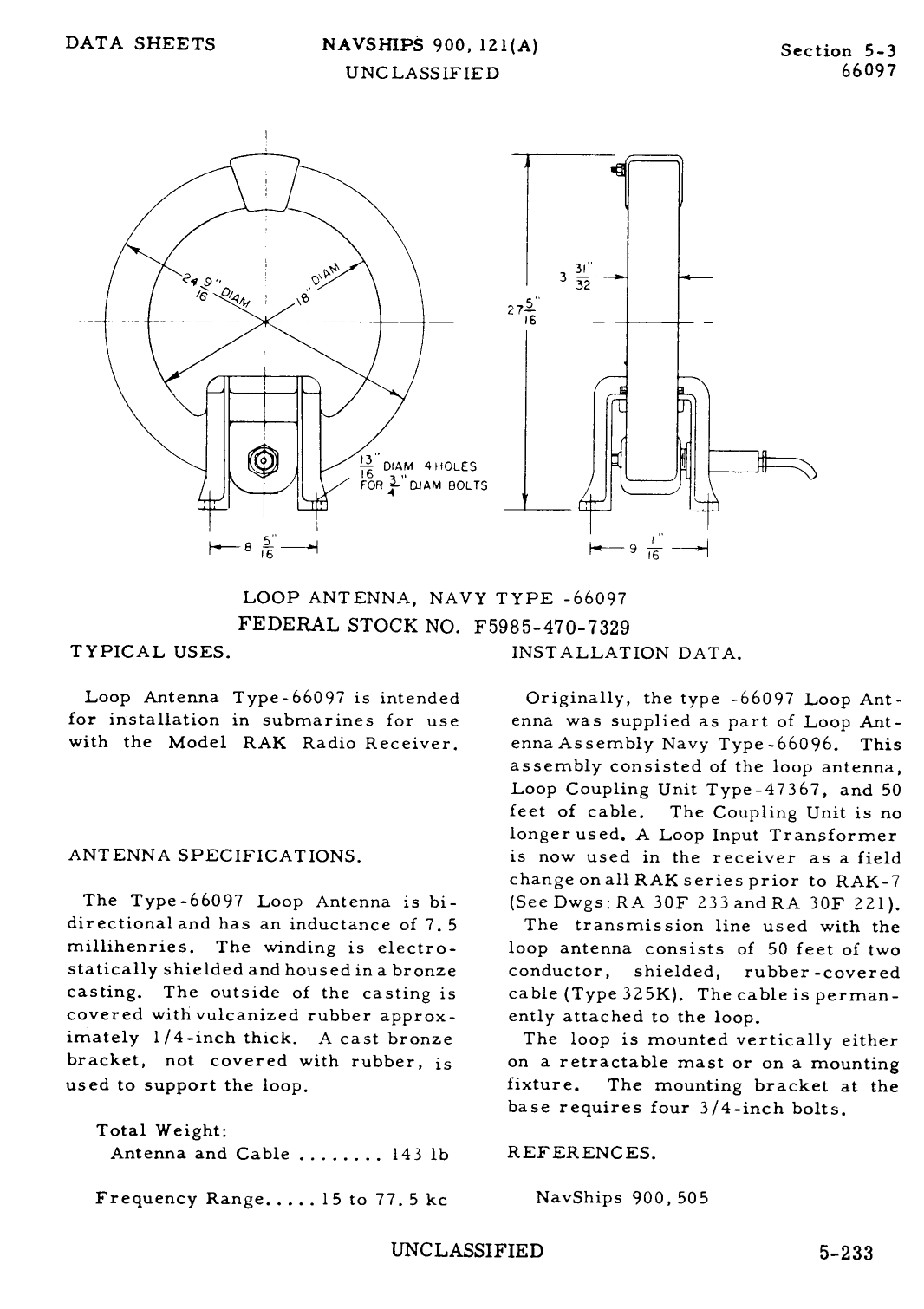
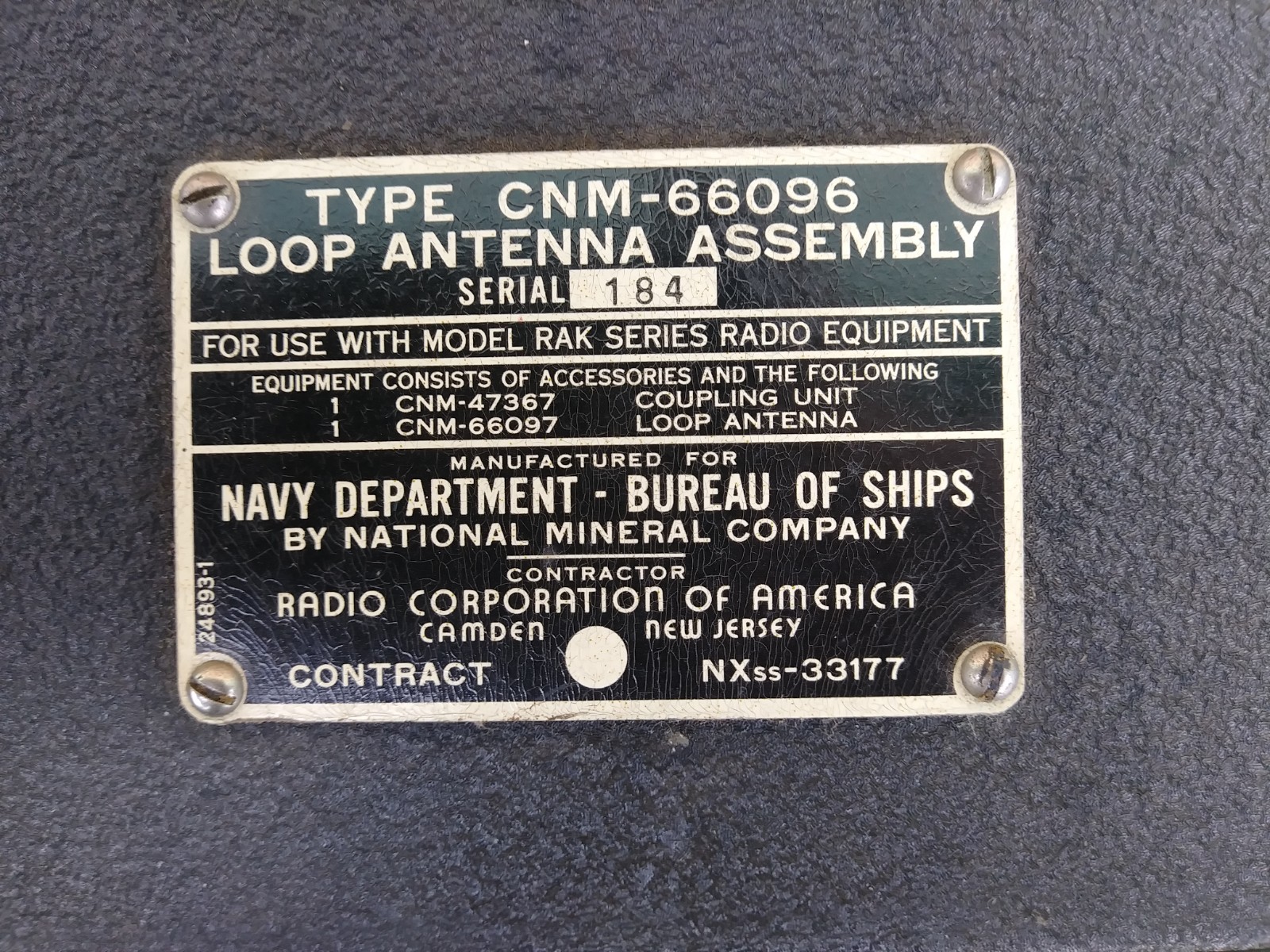
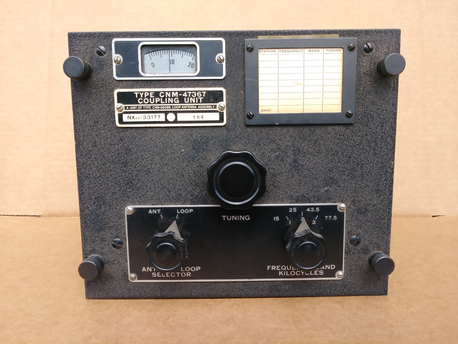
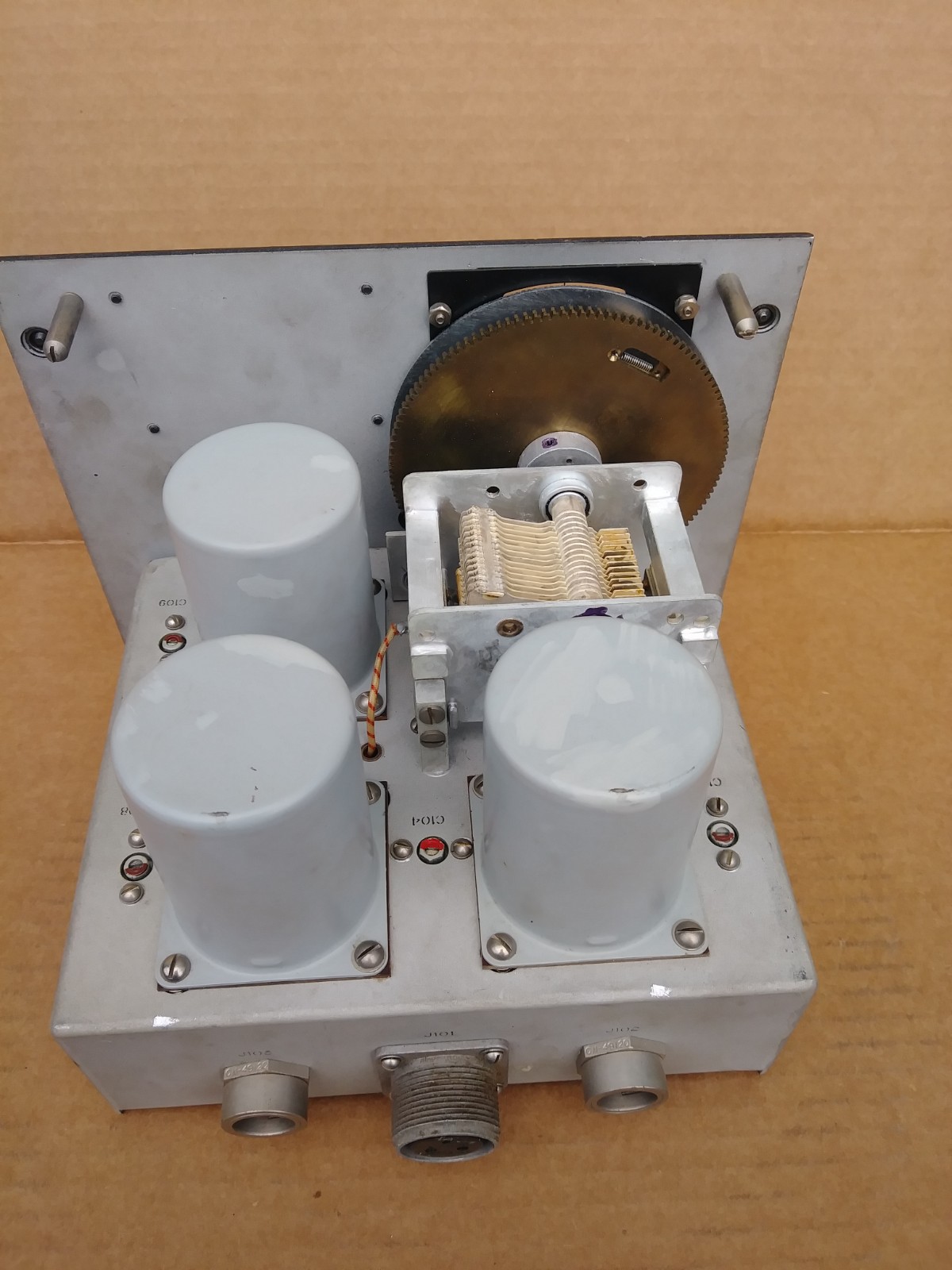
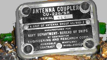
NT-66097 Loop Antenna
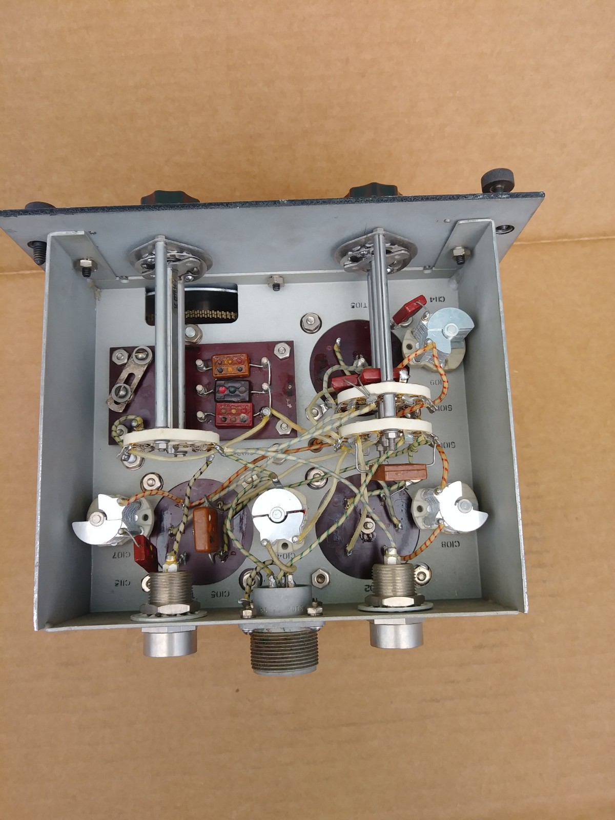
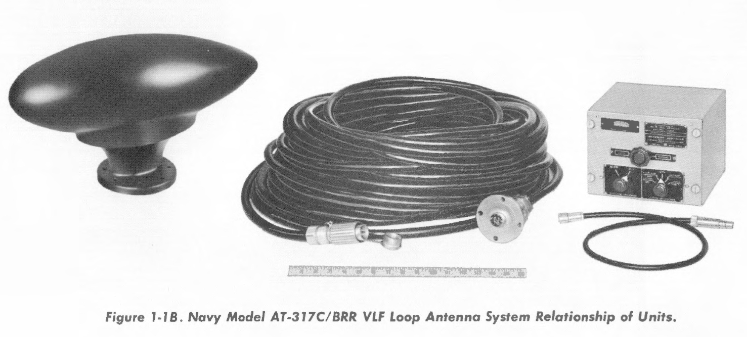
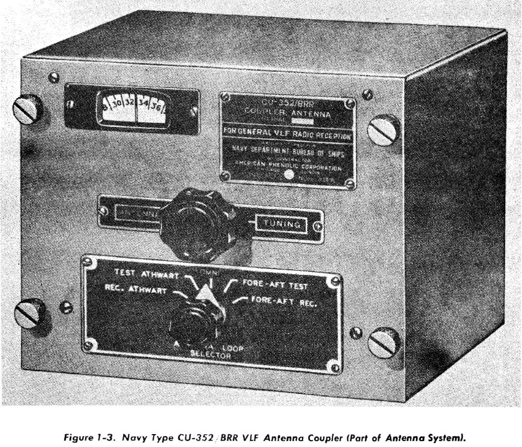
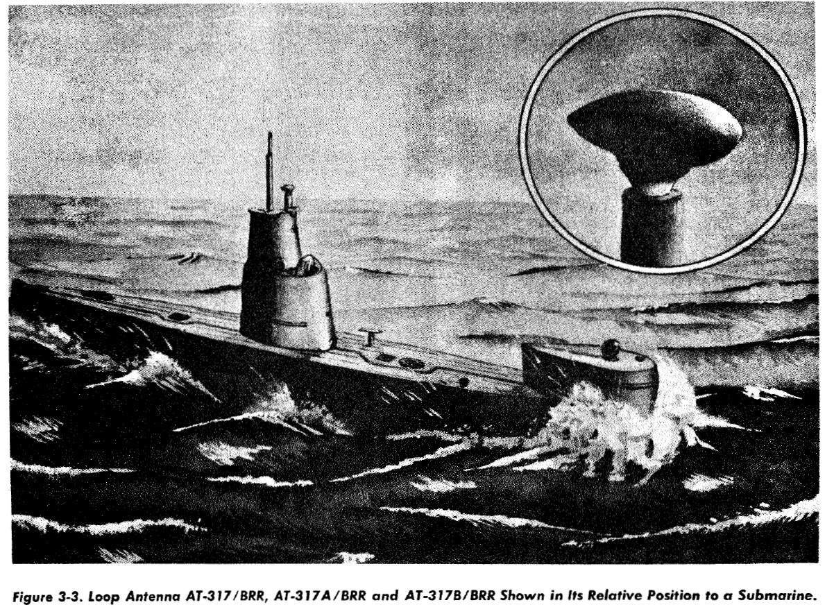
AT-317()/BRR VLF Loop Antenna for Submarines
Used with CU-352/BRR Coupler
NAVSHIPS 92182 Manual
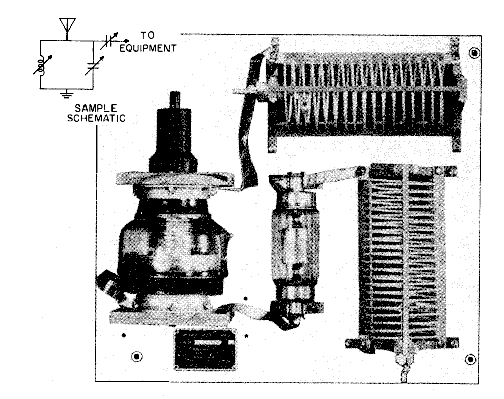
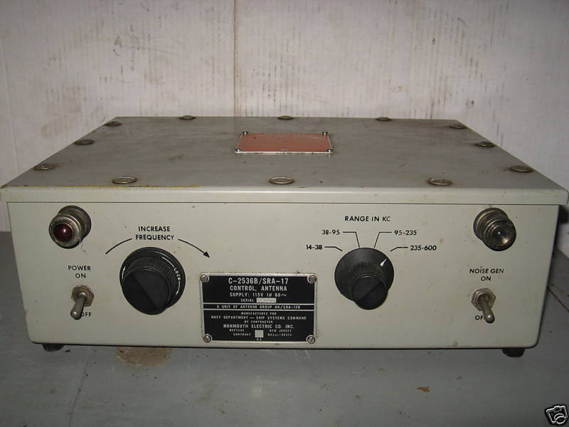
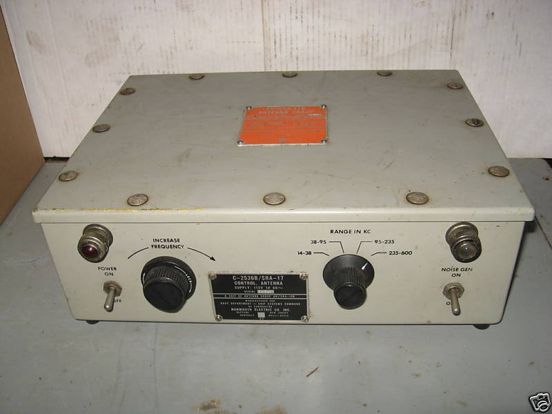
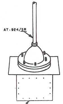
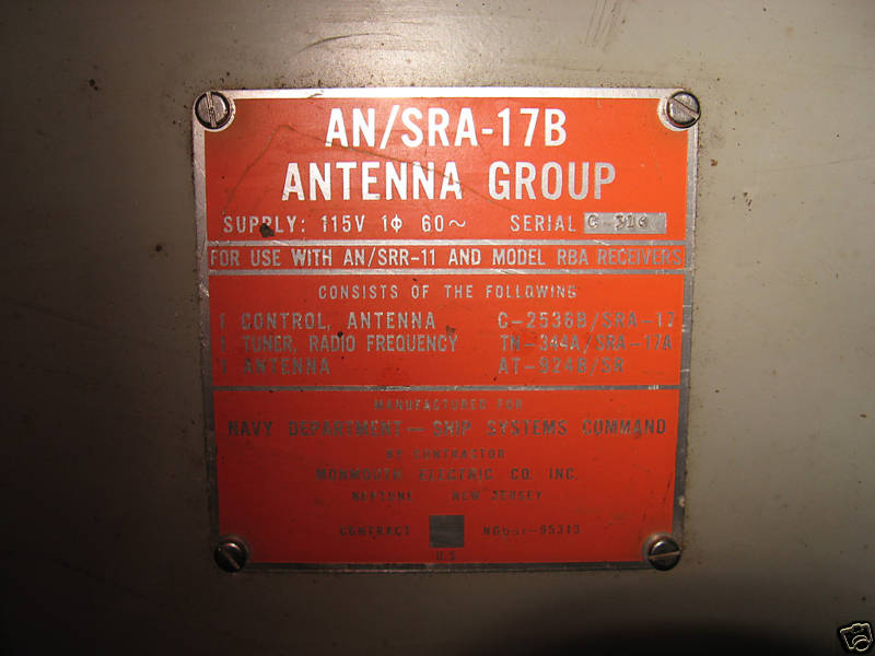
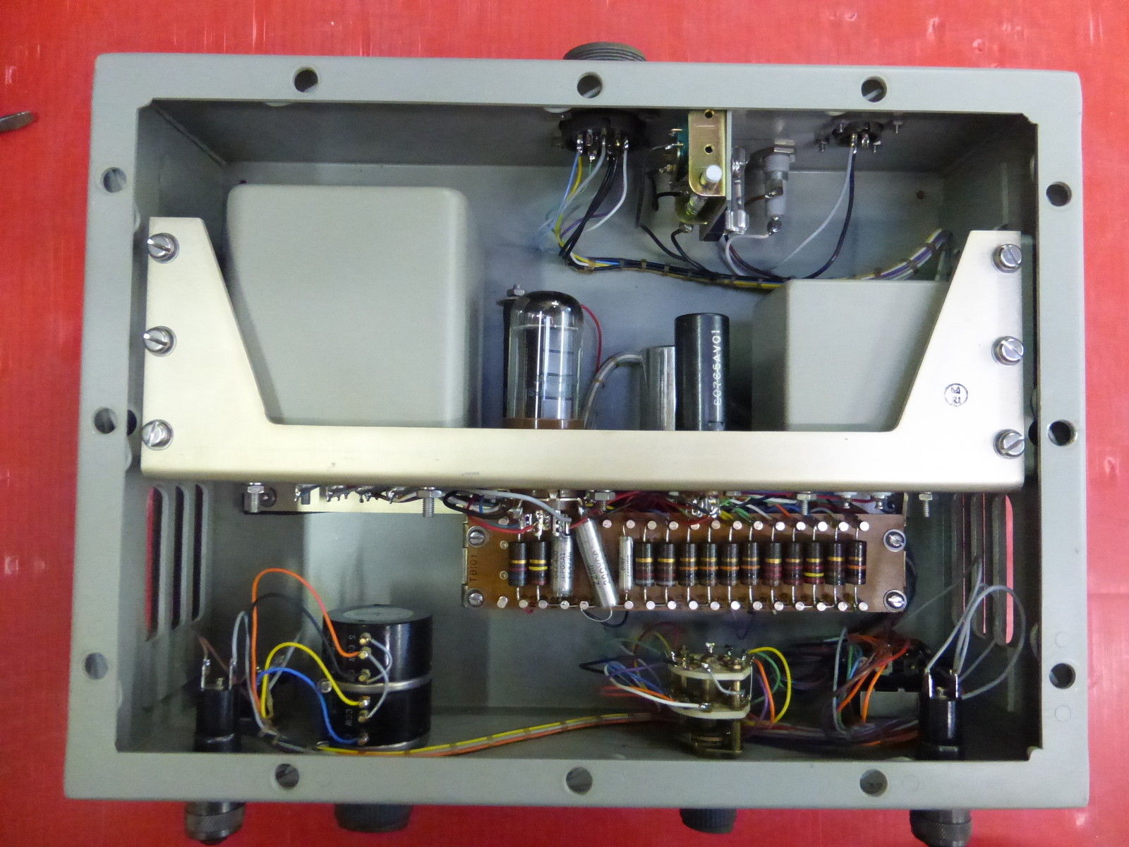
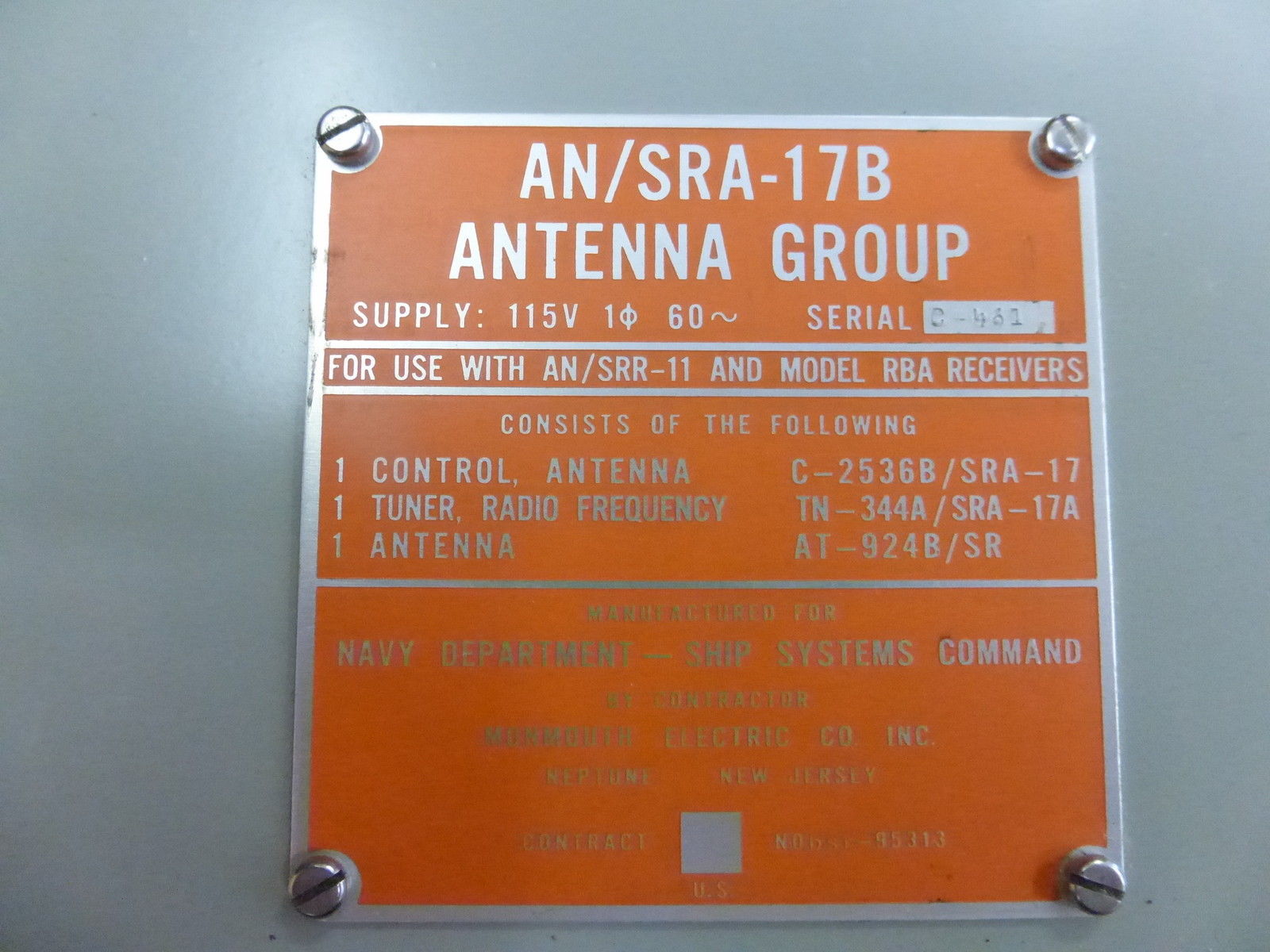
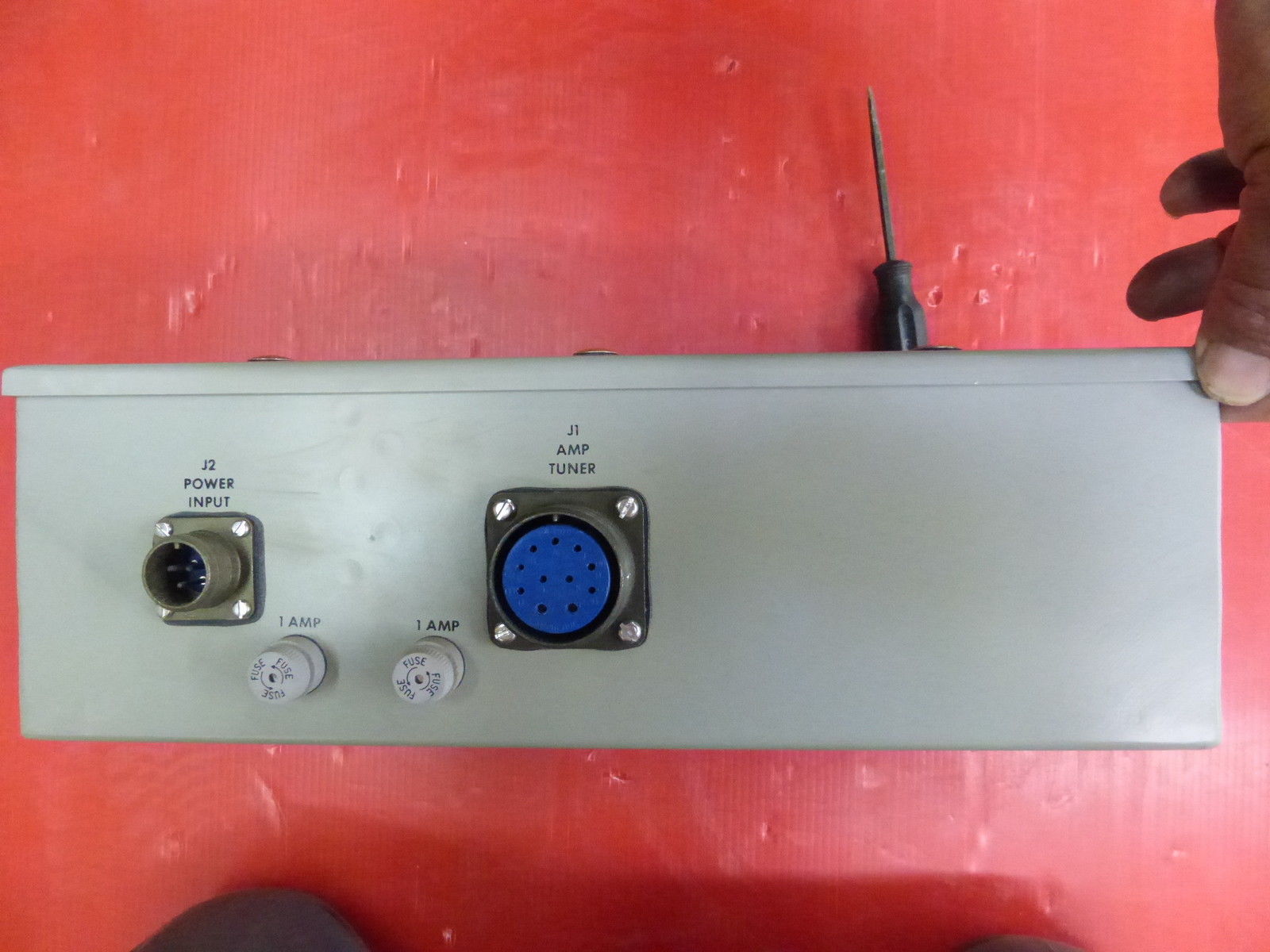
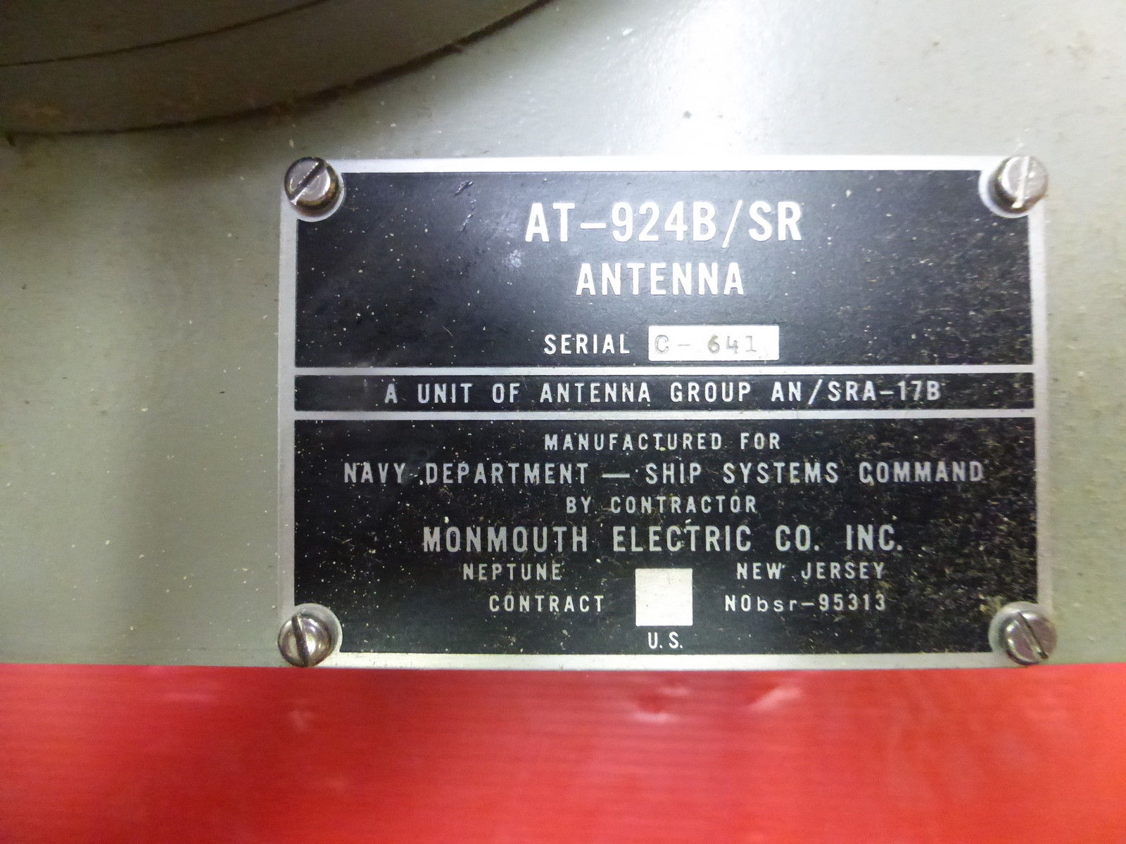
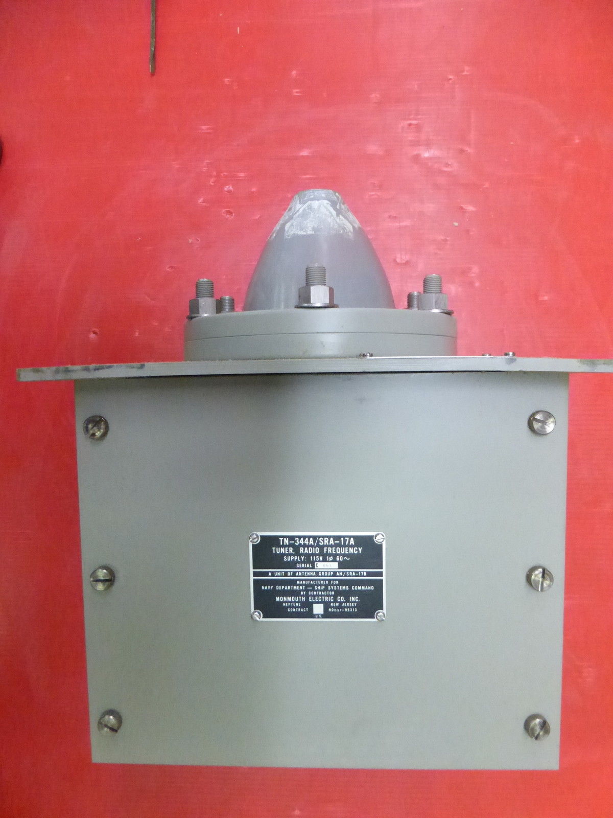
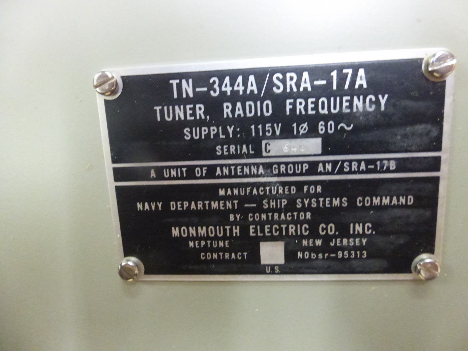
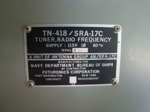
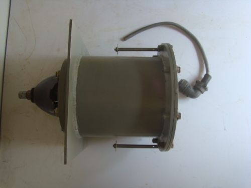
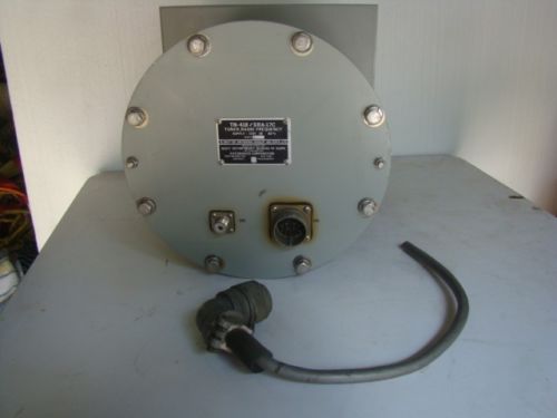
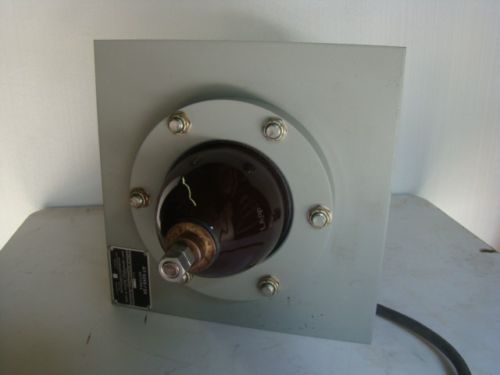
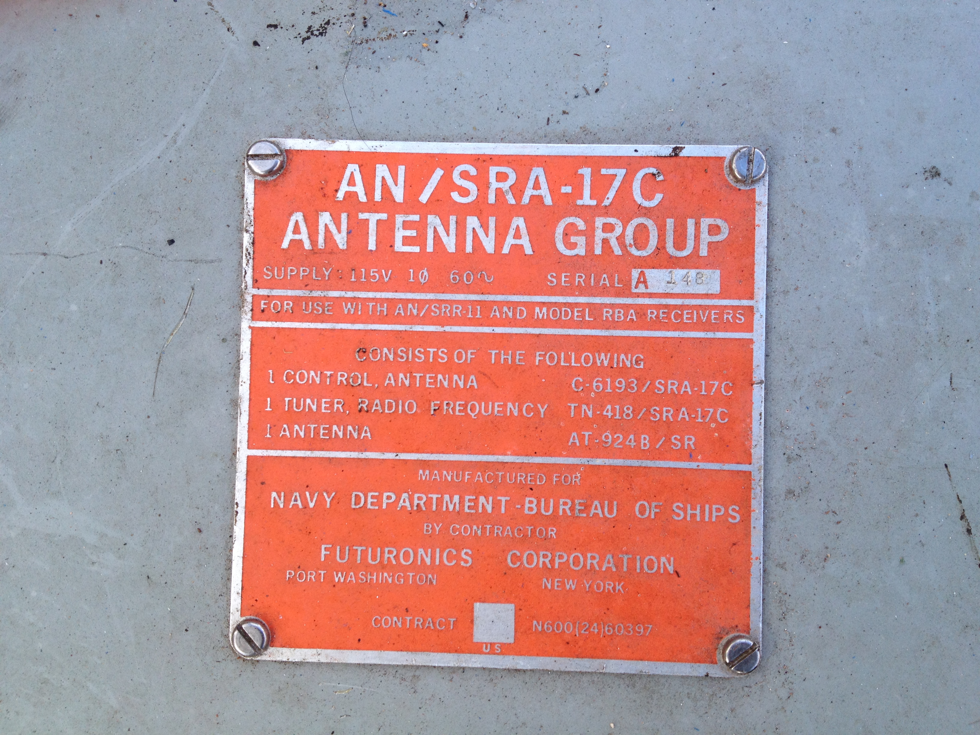
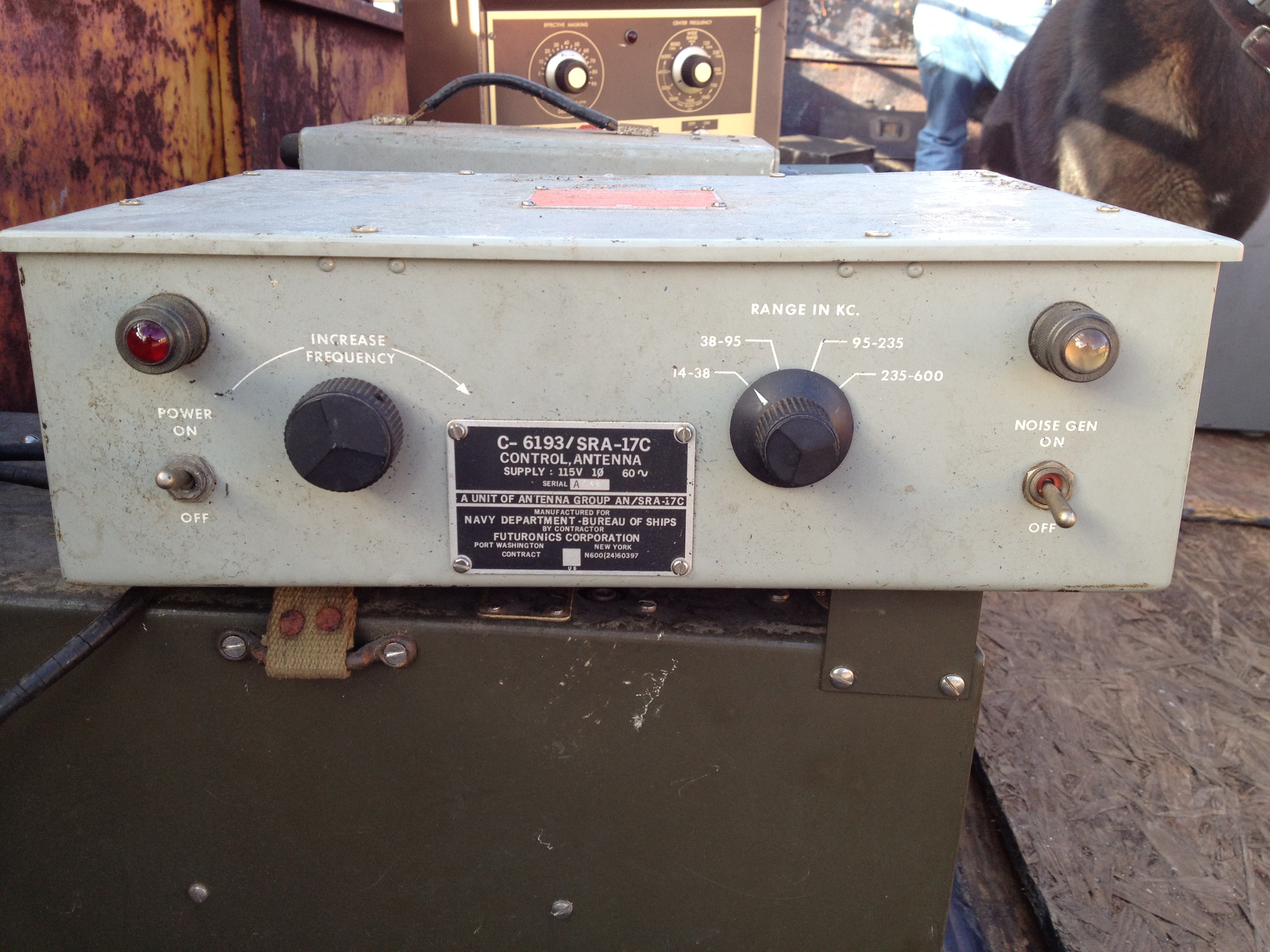
AN/SRA-17 LF/VLF antenna group
Components -
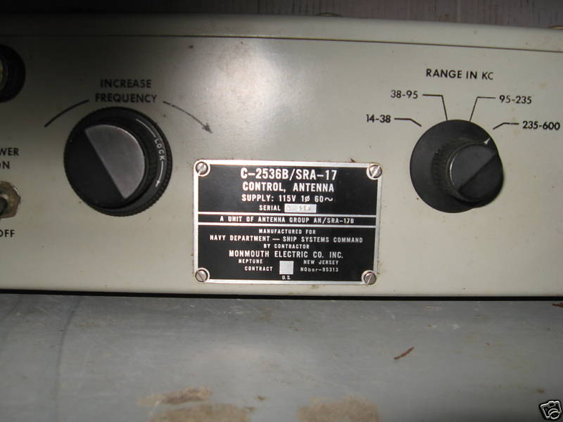
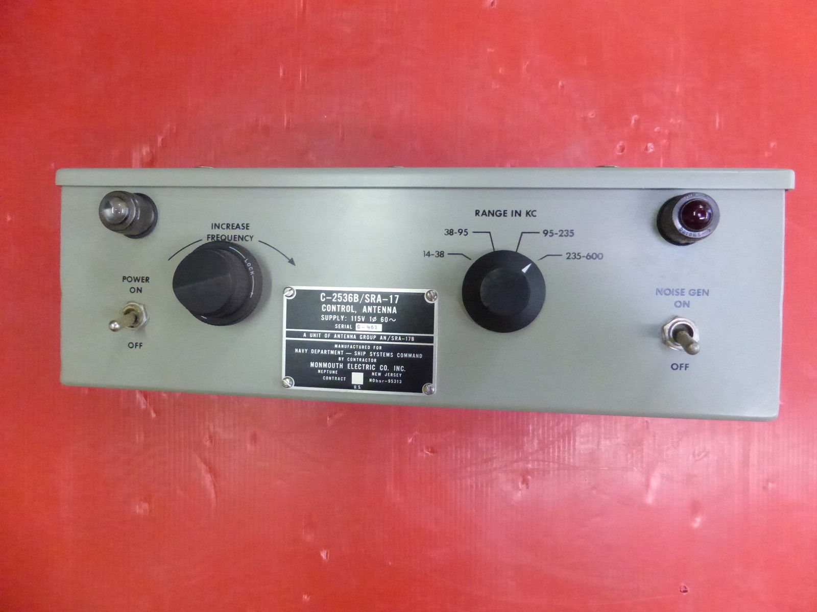
C-2536B/SRA-17 controller
TN-344A/SRA-17A tuner
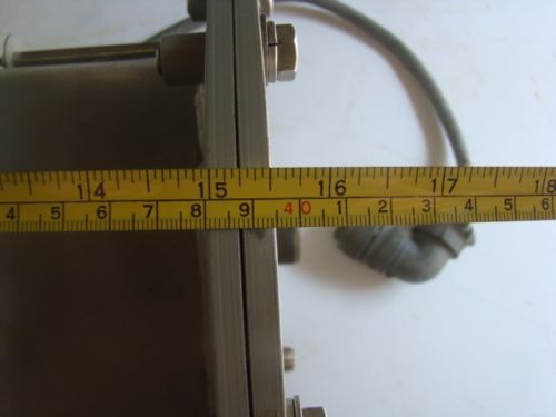
or TN-418/SRA-17C tuner
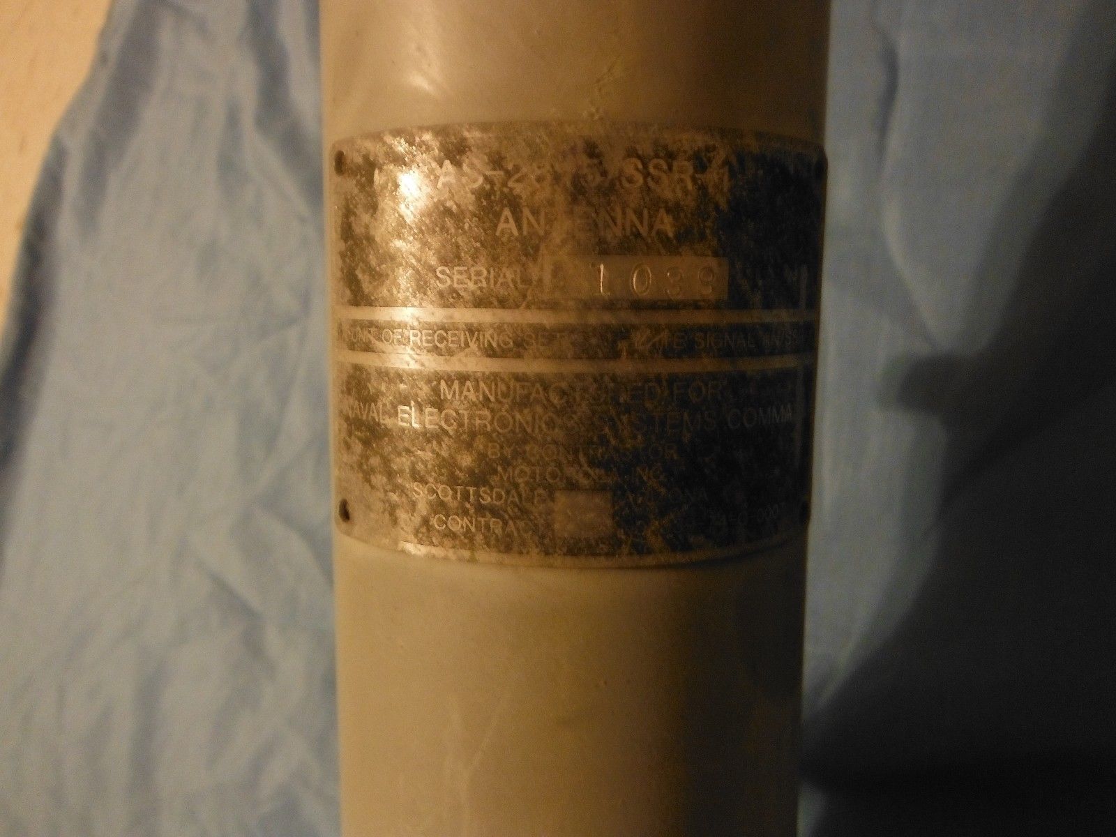
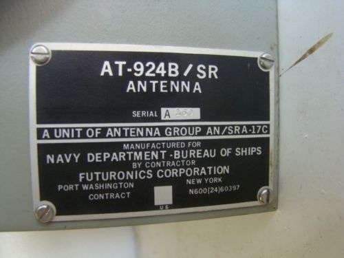
AT-924B/SR antenna
or AS-2687/SRA-17D antenna
manual NAVSHIPS 92299
manual NAVSHIPS 93205
C-2536B/SRA-17 controller
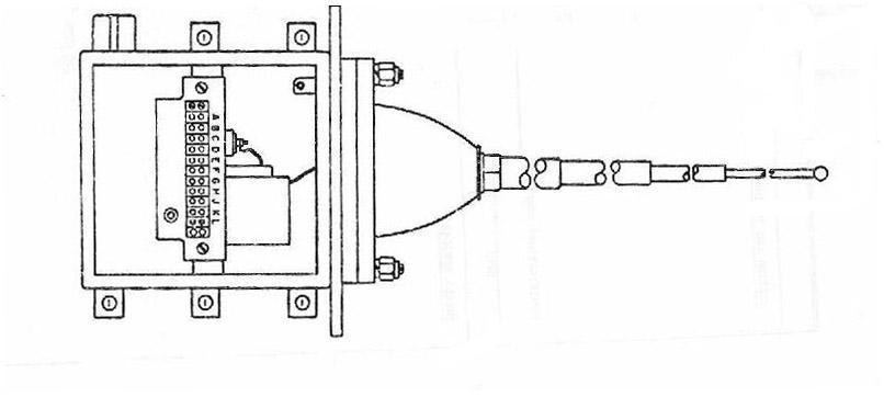
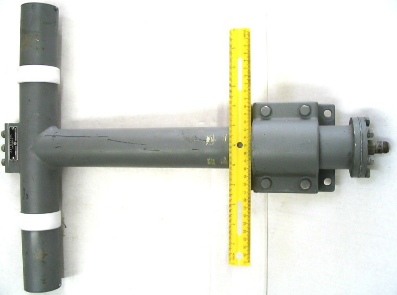
AT-924/SR Antenna is 129" long
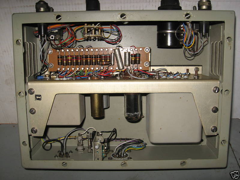
TN-334 or TN-418 tuner

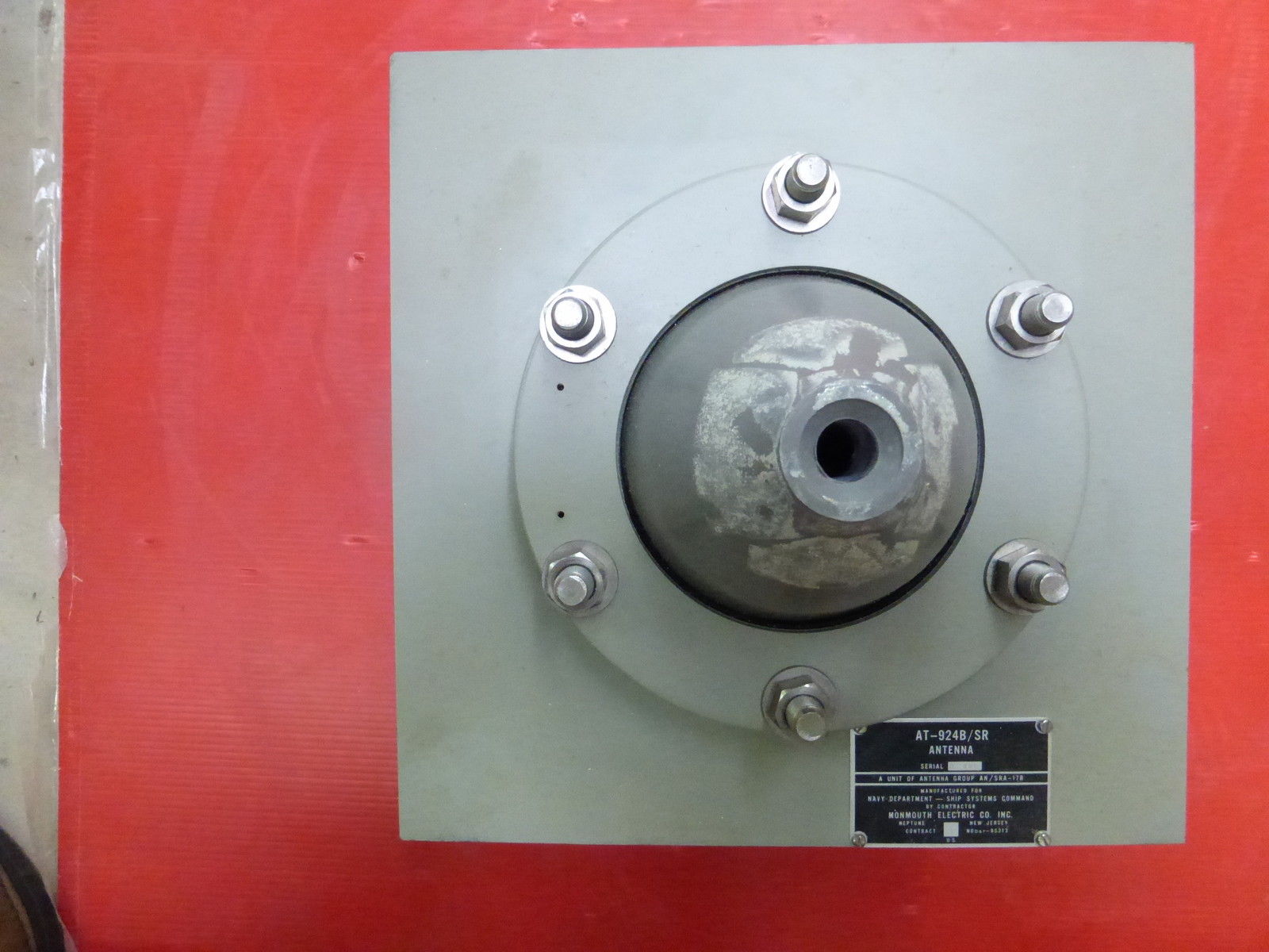
AS-2687/SRA-17D Antenna

130.25" overall


VHF/UHF Communications Antennas

NAVSHIPS 91292
Two-element collinear dipole array
225-400MHz
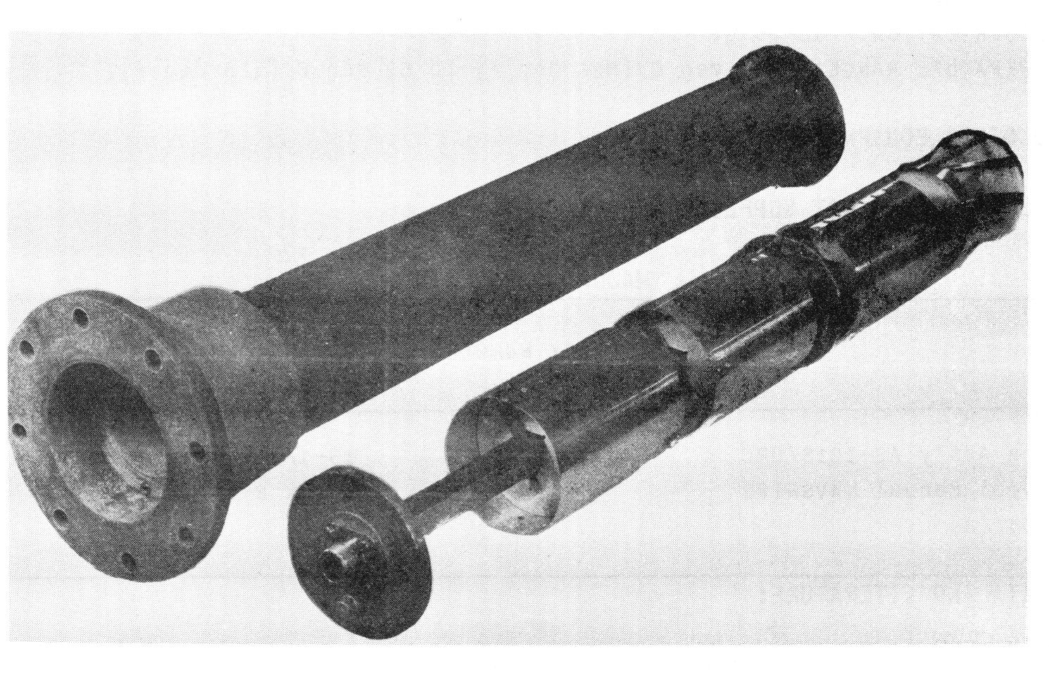
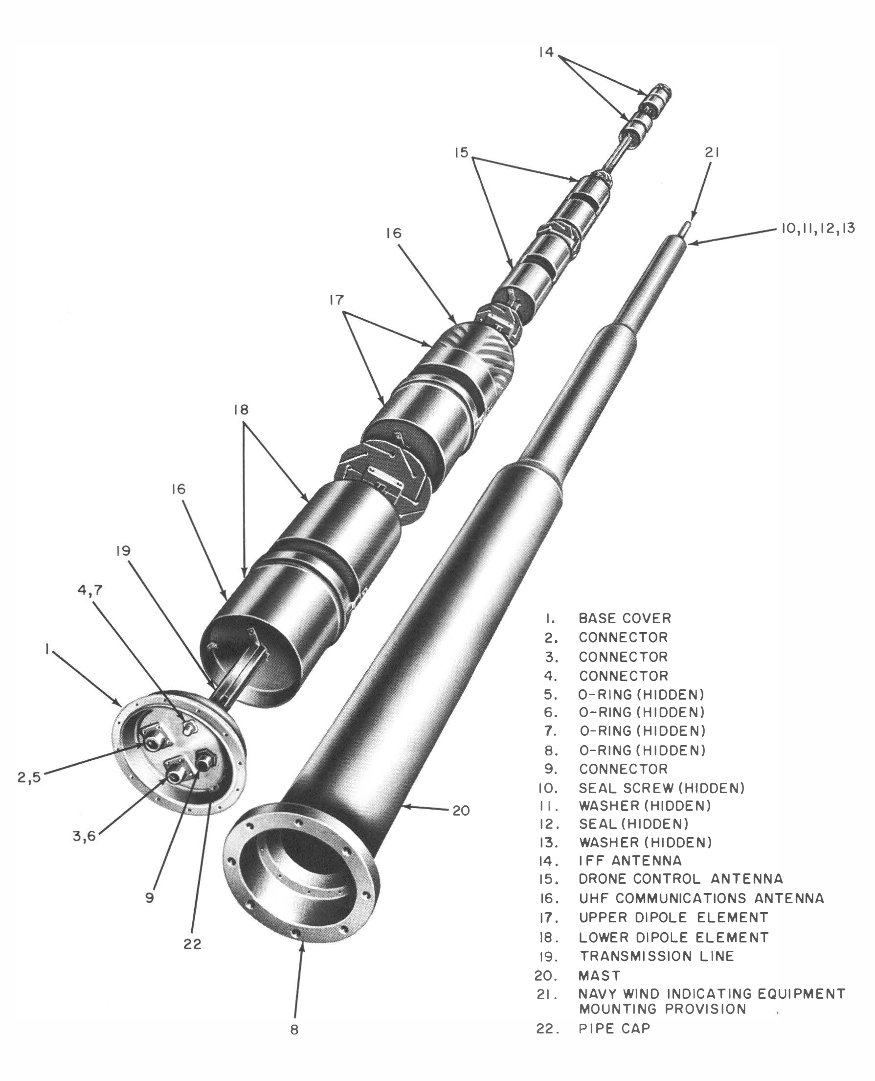
225-400mc UHF Communications
400-550mc drone control
1000-1150mc IFF
(Eggbeater)